Removal Procedure
Notice: Be careful not to damage the VIN plate when removing or replacing the upper
trim panel.
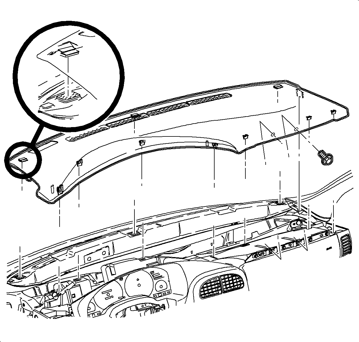
- Loosen the upper trim panel, but do not remove.
- Remove the screws located under the upper trim panel on the passenger
side of the vehicle.
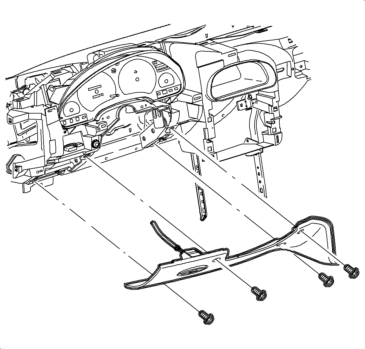
- Remove the steering column filler panel.
Notice: Do not remove weatherstrips. Adhesion will be lost if removed.
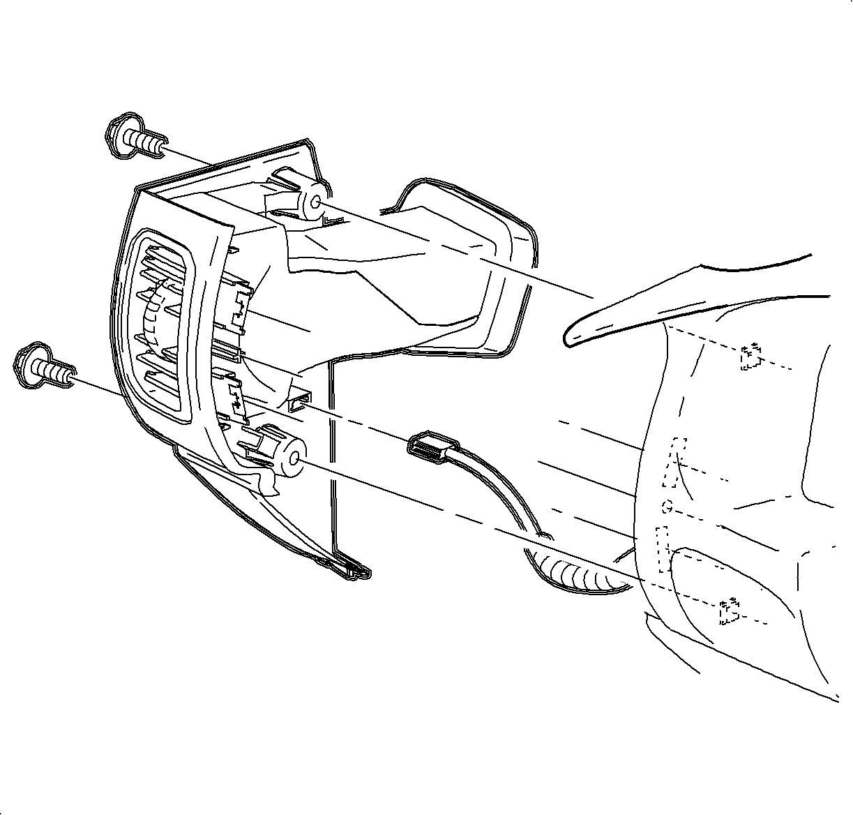
- Remove the left endcap assembly.
| 4.2. | Carefully disengage the clips at the I/P retainer assembly locations.
Use of a blunt tool will aid in disengaging the clips. |
| 4.3. | Maneuver the assemblies past the inner I/P retainer assembly and weatherstrips. |
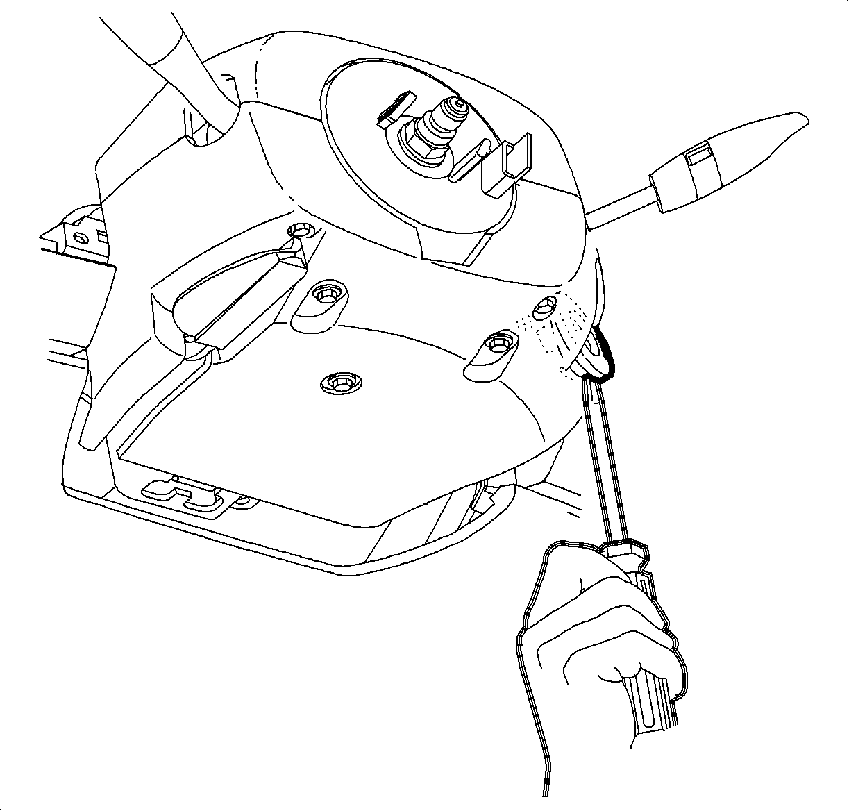
- Gently pry the edges of the ignition lock bezel with a blunt tool and separate
from the lower shroud.
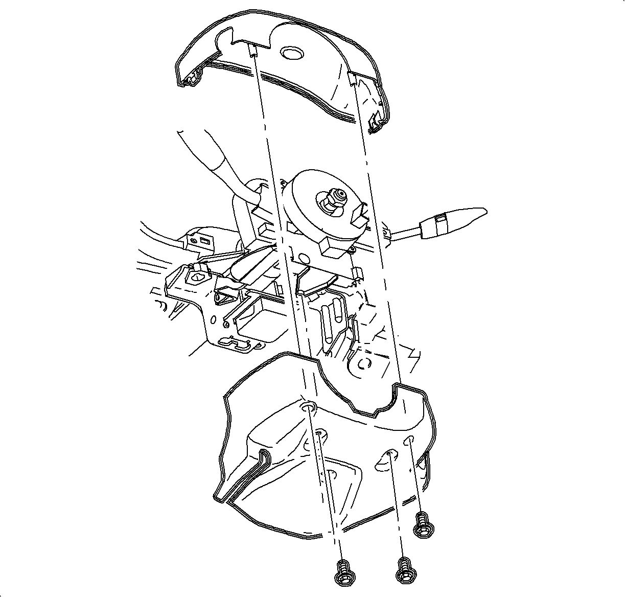
- Remove the screws and the lower steering column shroud.
- Lower the steering column by pushing down on the steering column adjusting
handle.
- Lift and remove the upper shroud from the steering column.
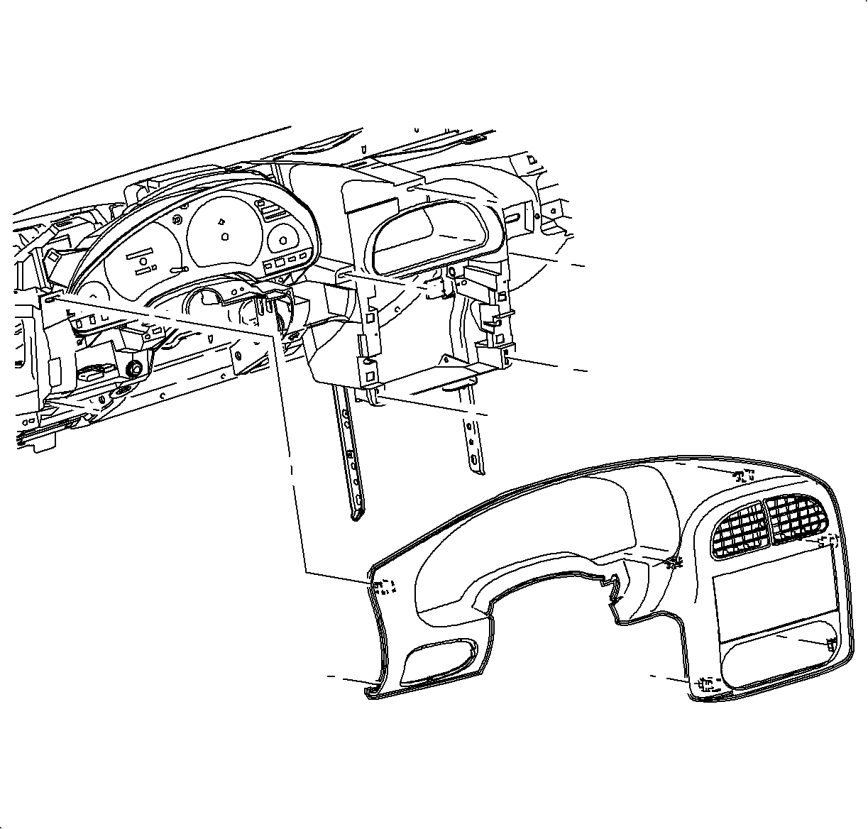
Important: It is not necessary to disconnect the I/P switch (dimmer/traction/fog) connector.
- Move the I/P bezel out of the way.
| 9.1. | Disengage the clips from the retainer assembly by grasping the edges of
the bezel near the clip location and pulling outward. |
| 9.2. | Move the I/P bezel to gain access to the radio fasteners. |
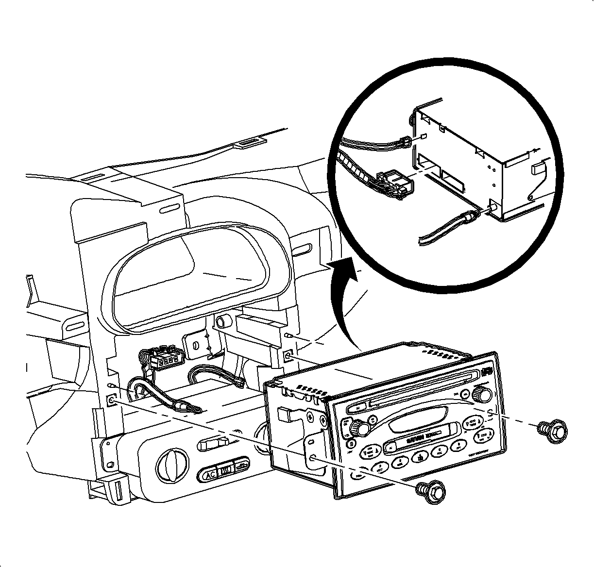
- Remove the radio:
| 10.1. | Remove the radio fasteners. |
| 10.2. | Pull the radio out slightly to access the rear of the radio. |
| 10.3. | Disconnect the electrical connector(s), antenna, and ground strap spade
terminal from the rear of the radio. |
Installation Procedure

- Install the radio.
- Connect the radio ground strap spade terminal, electrical connector(s),
and antenna to the rear of the radio.
- Install the radio by sliding the radio into the guides on the instrument
panel.
Notice: Refer to Fastener Notice in the Preface section.
- Install the fasteners.
Tighten
Tighten the radio-to-I/P fasteners to 2.5 N·m (22 lb in).

- Install the I/P cluster bezel.
- Position the I/P cluster bezel by lining up clip location.
- Snap the I/P cluster bezel in place by pushing at clip locations.

- Position the upper steering column shroud.
- Position the lower steering column shroud and install the screws.
Tighten
Tighten the steering column shroud fasteners to 1.5 N·m (13 lb in).

- Install the ignition bezel.
| 10.1. | Align the peg of the ignition bezel with the cut-out in the lower shroud. |

Important: Ensure that endcap bottom portion is inside of the filler panel assembly.
- Install the left endcap assembly.
- Maneuver the assembly past the inner I/P retainer assembly and weatherstrips.
- Snap the clips into the I/P retainer assembly locations.
- Install the fasteners.
Tighten
Tighten the I/P endcap-to-I/P fasteners to 2.2 N·m (19 lb in).

- Install the steering column filler and fasteners.
Tighten
Tighten the steering column filler panel fasteners to 2.2 N·m (19 lb in).

- Install the I/P upper trim panel.
| 16.1. | Position the upper trim panel on the retainer assembly. |
| 16.2. | Align the tabs on sides of the upper trim panel with openings in the windshield
garnish molding. |
| 16.3. | Align the clips and clip location. |
| 16.4. | Firmly snap in the clips at clip locations. |
- Install the fasteners on the underside of the upper trim panel on the
passenger side of the vehicle.
Tighten
Tighten the I/P upper trim panel fasteners to 6 N·m
(53 lb in).


