
| Subject: | Vehicle Vibration at Speeds Between 77-87 km/h (48 - 54 mph)
(Install Powertrain Damper Kit) |
| Models: | 2000-- 2002 Saturn S-Series vehicles |
Due to the addition of 2002 model year vehicles under Models
Affected, this bulletin has been revised and supercedes bulletin 00--T-57,
which should be discarded.
Condition
Some customers may comment about a vehicle vibration that occurs between 77
- 87 km/h (48 - 54 mph) on smooth road surfaces.
This vibrations most noticeable in the vehicle floorboards and/or in the seat
cushions. It only occurs within the specified speed range of 77
- 87 km/h (48 - 54 mph) and only on smooth to very smooth road surfaces.
Cause
This condition may be caused by insufficient damping between the engine cradle
and the powertrain.
Correction
Refer to the procedure in this bulletin to verify condition and, if required;
install powertrain damper kit.
Procedure:
General Diagnostic Information
Since the powertrain damper kit is designed to correct a very specific vibration,
it is important that all other possible causes of vehicle vibration be eliminated
before installing the kit. Since a road test is necessary, it is important that the
following checks are performed.
Important: Perform all
of the following checks before road testing
vehicle.
| • | Check for debris build-up on the tires and/or wheels. |
| • | Check tires for thread distortions, separation, bulges from impact, and
abnormal or excessive wear. |
| • | Check for missing or loose wheel weights. |
| • | Check for bent and./or damaged wheels. |
| • | Check for missing or loose wheel weights. |
| • | Check for loose or missing wheel lug nuts. |
| • | Check for proper tire bead seating on rim of wheel. |
| • | Make sure the wheel and tire assemblies are within specification for radial
and lateral runout. |
| • | Make sure the wheel and tire assemblies are correctly balanced to the
nearest 0.10 oz. |
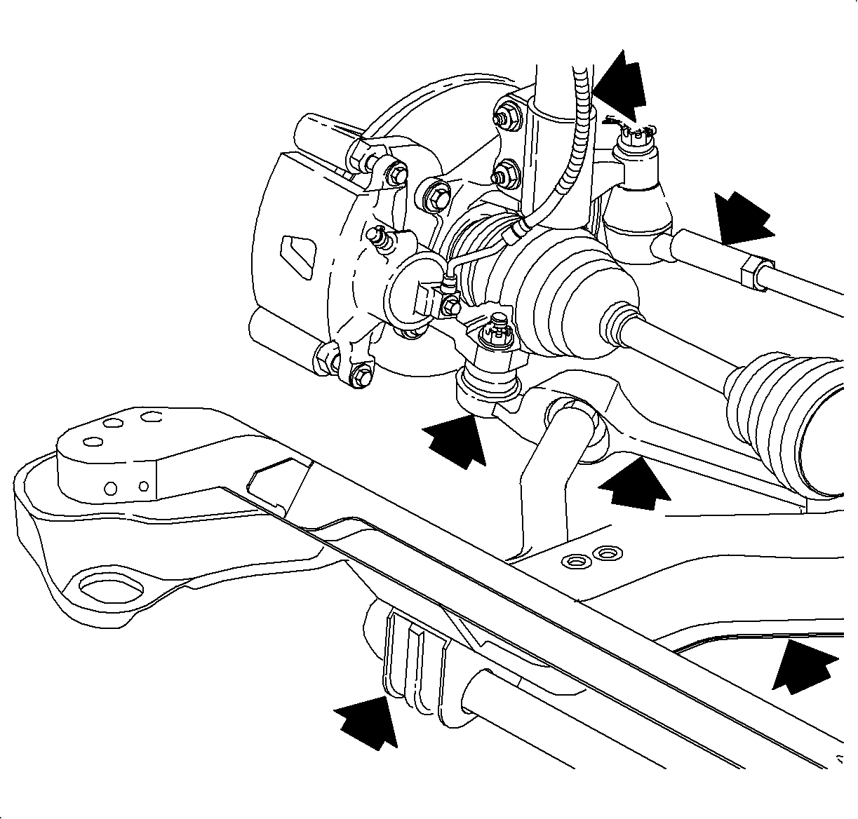
| • | Check front suspension components for excessive
wear and/or damage: |
| - | Check if cradle is bent. |
| - | Check tension strut bushings for wear or damage |
| - | Check lower control arms for worn ball studs, worn bushings, or bent arms. |
| - | Check steering gear for wear or damage. |
| - | Check inner and outer tie rod ends for wear or damage. |
| - | Check strut assemblies for wear, binding and to make sure they are no
bent. |
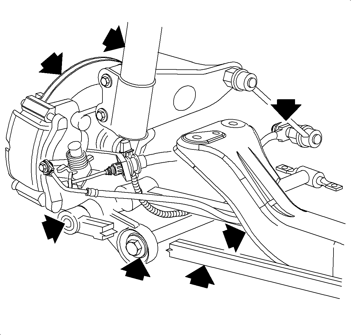
| • | Check rear suspension components for excessive
wear and/or damage: |
| - | Check if the cross support is bent. |
| - | Check trailing arms to see if the bushings are worn or if the arms are
bent. |
| - | Check lateral links to see if the bushings are worn or if the arms are
bent. |
| - | Check stabilizer bar on vehicle so equipped for worn or missing bushings,
and to verify that the stabilizer bar is not bent. |
After checking the above items, road test the vehicle on a smooth road surface
while very gradually accelerating the vehicle from 77-87 km/h (48-54 mph). If
the vehicle is equipped with cruise control, it is convenient to use it to accelerate
the vehicle at 2 km/h (1 mph) increments.
A vibration may start between 77 - 87 km/h (48--54 mph). It may grow
more pronounced as the vehicle maintains a steady speed within the 77--84 km/h
(48-54 mph) speed range on a smooth surface. Any rough areas in the road such as expansion
joints or any irregularities in the road surface will interrupt the vibration, causing
a need to restart the road test.
Install the powertrain damper kit under these circumstances only:
| • | When all other possible causes for vehicle's vibration have been eliminated. |
| • | When a continuos vibration occurs only between 77-87 km/h (48--54
mph) and the vibration is most pronounced in the vehicle floorboards and seat cushions. |
| - | Install P/N 21012637 if vehicle is equipped with automatic transaxle. |
| - | Install P/N 21012638 if vehicle is equipped with a manual transaxle. |
The powertrain damper kit comes with the damper installed tot he upper bracket.
The powertrain damper kit has two steel washers and two rubber grommets attached to
the damper's shaft. One M8 x 20 mm bolt, one M8 nut, and one M6 nut are included in
each kit. Each kit contains a lower bracket. There are two lower racket designs, one
for automatic transaxles and one for manual transaxles.
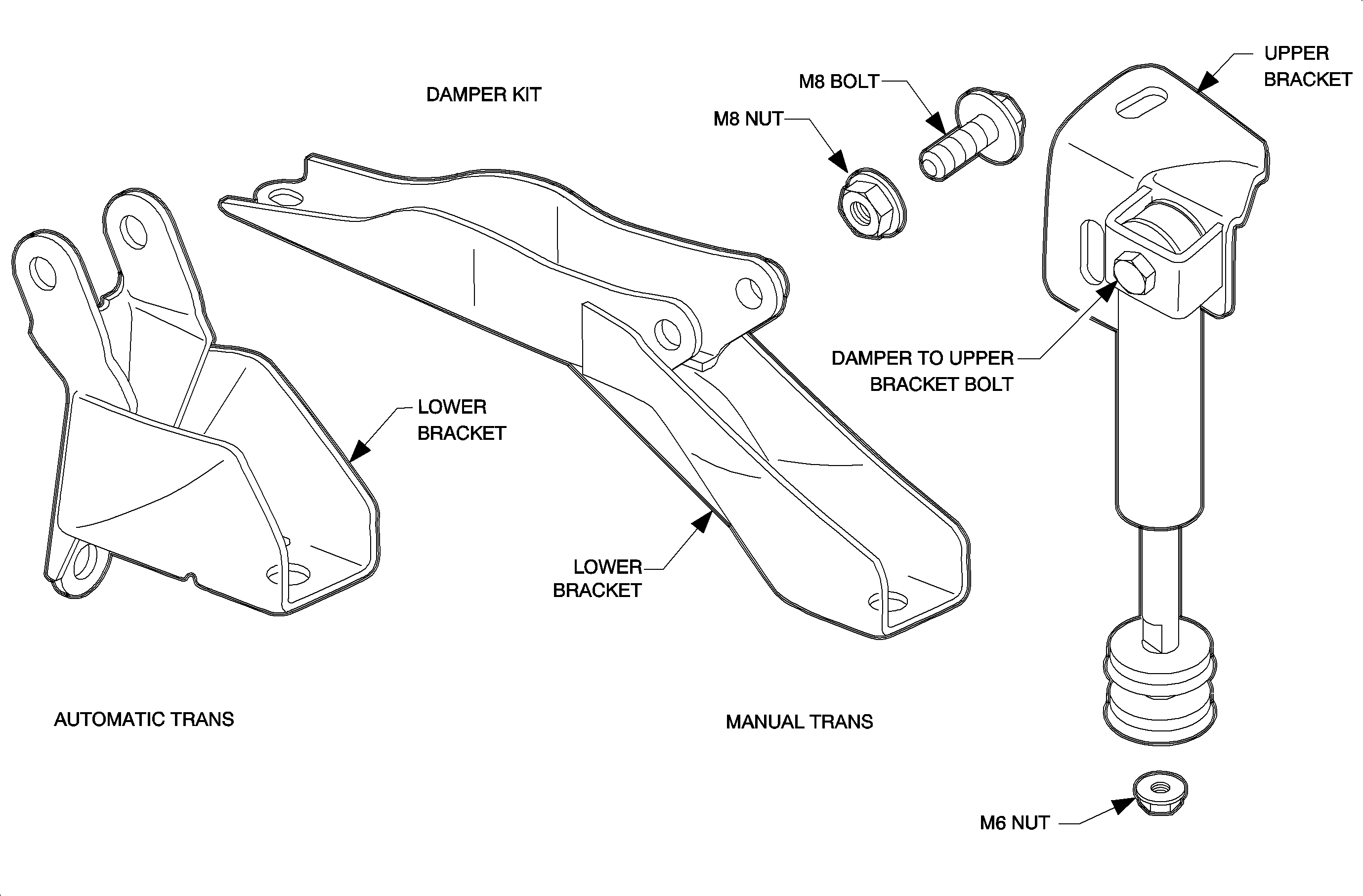
The powertrain damper kit installs between the left midrail and the transaxle.
Utilizing the forward battery fastener(s), the upper bracket attaches to the midrail,
underneath the battery tray. The lower bracket (a modified transaxle strut bracket)
attaches tot he transaxle at the same location as the transaxle strut bracket. The
damper itself attaches tot he upper bracket with an M10 x 40 mm bolt and to lower
bracket with steel washers and the rubber grommets held in place with an M6 nut.
Bench Assembly of Damper-to-Lower Bracket
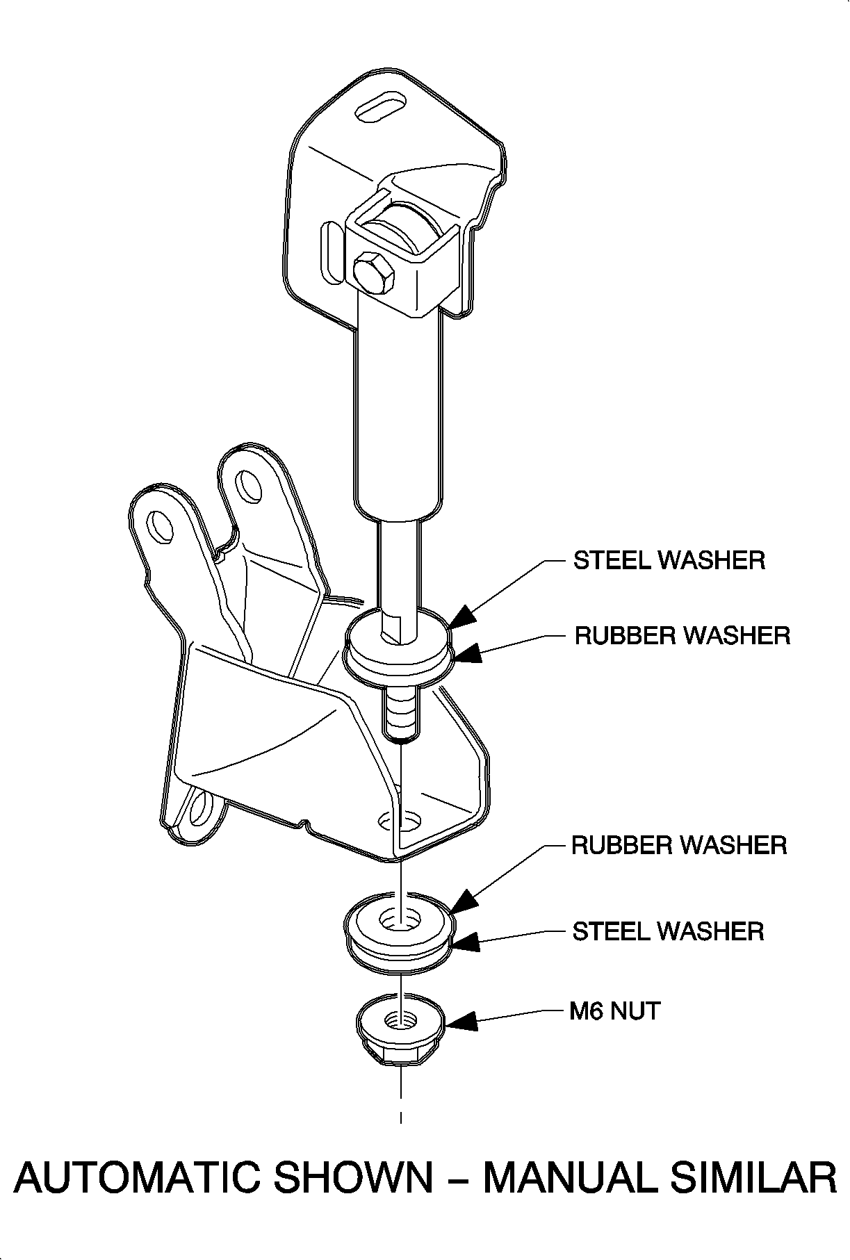
- Remove the first rubber grommet and the first
steel washer from the damper shaft.
- Install the damper shaft into the appropriate lower bracket; install the
rubber grommet and then the steel washer onto the damper shaft.
- Install the M6 nut to the damper shaft. To tighten the nut, hold the flats
on the damper shaft with a 7 mm wrench.
Tighten
Damper-to-Lower Bracket: Nut to 10 N·m (89 in lbs)
- after damper is assembled, proceed to "Damper installation on Vehicle."
Damper Installation on Vehicle
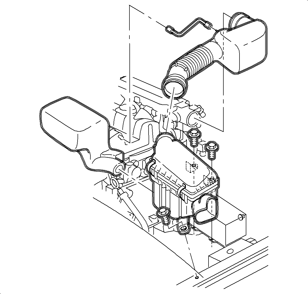
- Remove air induction system.
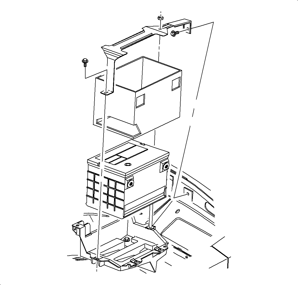
- Remove battery.
| 2.1. | Disconnect negative battery cable. |
| 2.2. | Disconnect positive battery cable. |
| 2.3. | remove battery hold down bracket fasteners and remove bracket. |
| 2.4. | Lift battery out of vehicle and place in a safe location. |
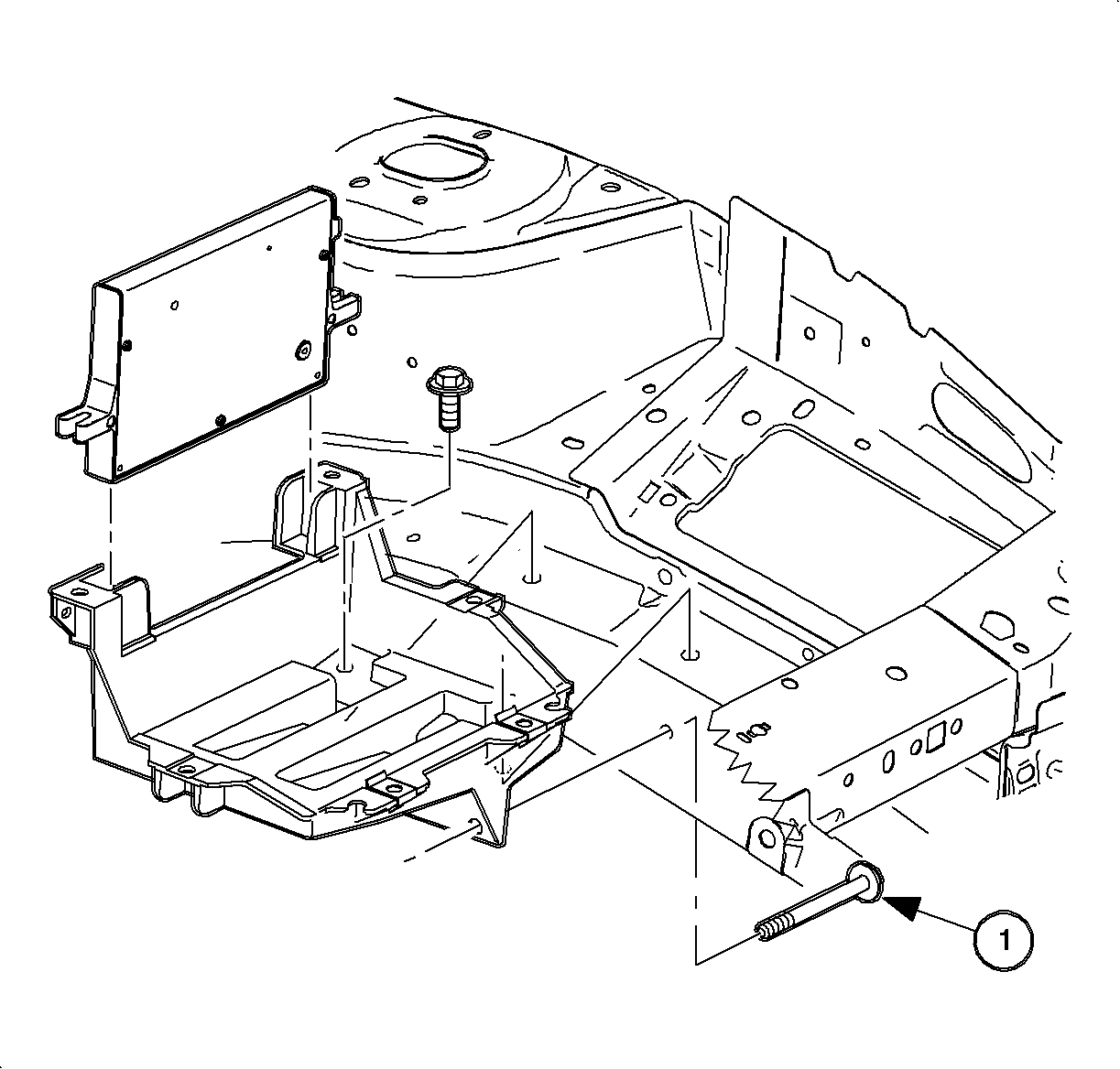
- Remove battery tray.
| 3.1. | Remove battery attachment bolts. (One bolt is located in fender well area.) |
| 3.2. | Remove PM attachment bolts and lay PCM aside. |
| 3.3. | Unclip battery cables from battery tray. |
| 3.4. | Remove battery tray from vehicle. |
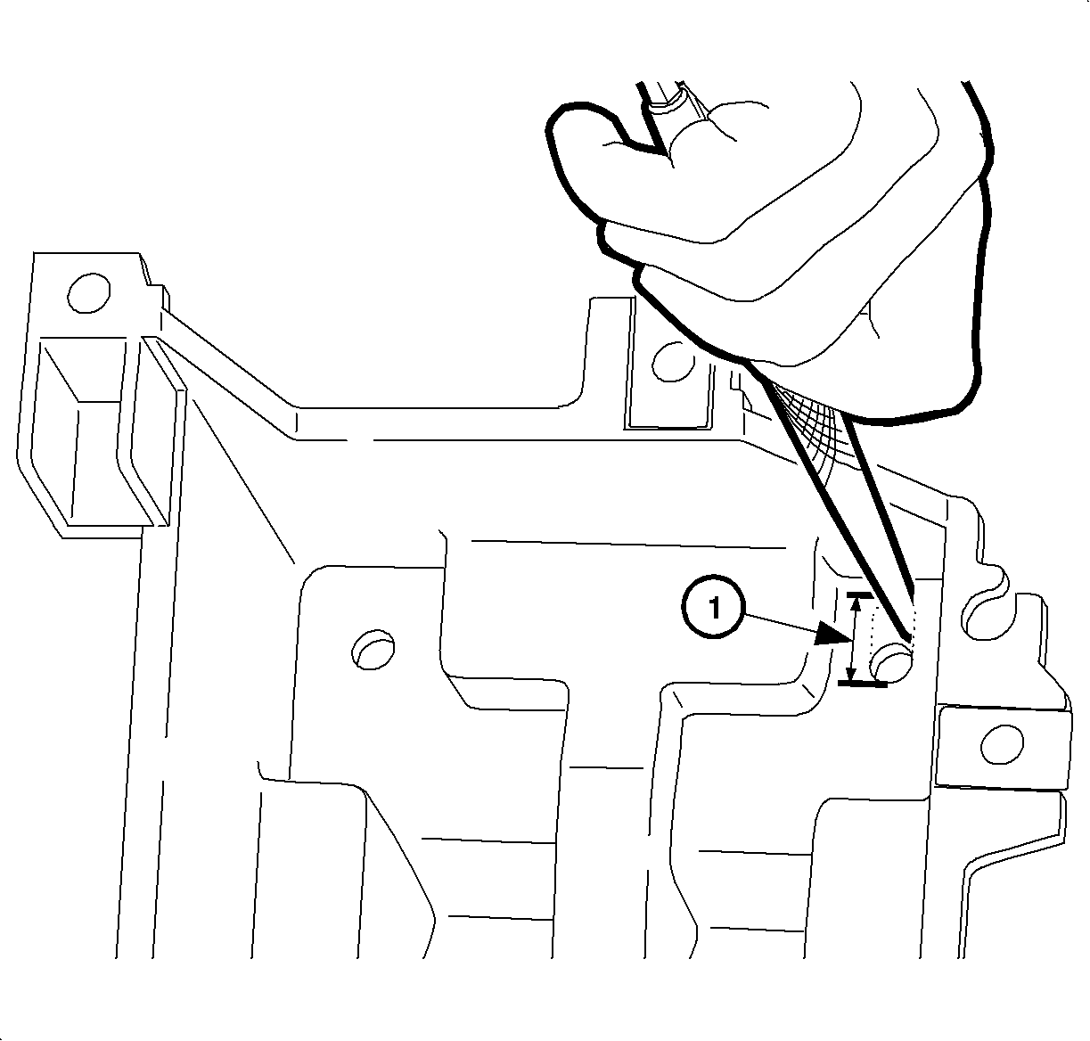
Important: Do not make the slot any wider than the original width of the hole. Make sure
to slot the hole outboard (toward the left front tire if the battery tray was mounted
in the vehicle).
- Modify battery tray front vertical bolt hole.
| 4.1. | Place battery tray in a vice. |
| 4.2. | Use a rat--tail file to elongate the front vertical bolt hole. Create
an oblong slot measures 18 mm (23/32 in.) at location (1) shown in illustration. (This
is approximately an 8 mm [5/16 in.] increase in the size of the existing bolt hole.) |
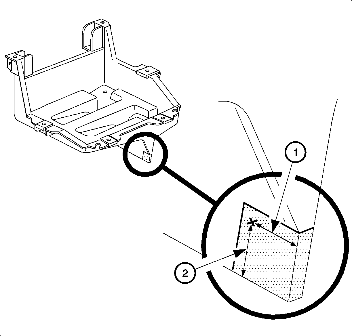
- Remove corner of battery tray.
| 5.1. | Refer to illustration and mark location of pilot hole to be drilled. |
| • | Dimension (1) should be 30 mm (1 3/16 in.) |
| • | Dimension (2) should be 27 mm (1 1/16 in.) |
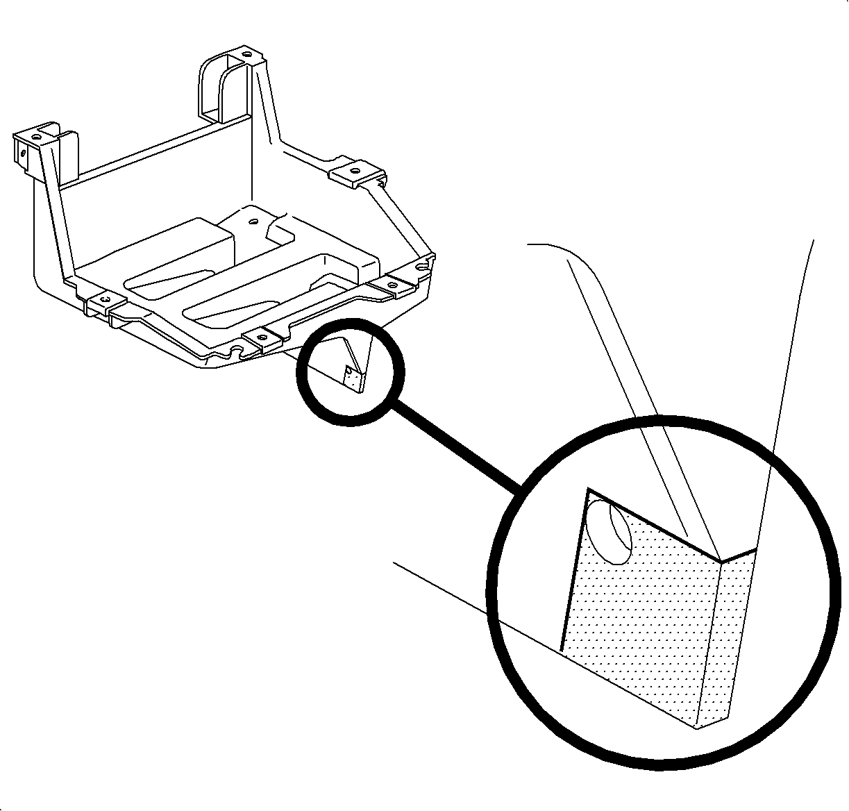
| 5.2. | Drill a 5 mm (3/16 in.) hole at marked location. |
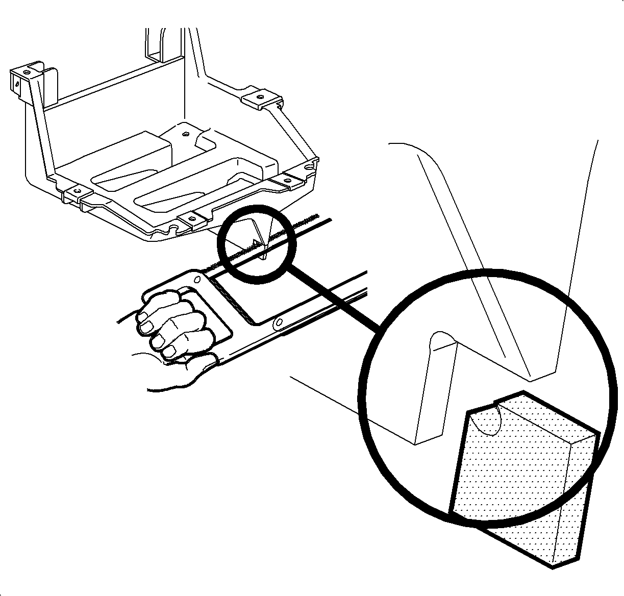
| | Notice: It is essential to maintain a rounded corner in the cutout section of the battery
tray. This rounded corner will help relieve stress at the corner and prevent the battery
tray from cracking.
|
| 5.3. | Use a hacksaw to cut in from the bottom and the side of the battery tray to
remove remainder of battery tray corner. |
- remove transaxle strut. (Refer to "Transaxle Strut" in the
Powertrain Mounts section of the 2000-2002 S-Series Chassis Service Manual.)
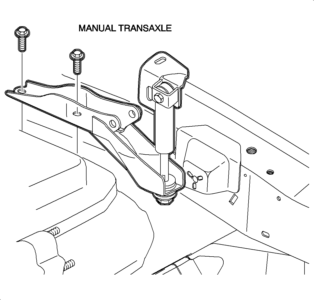
- Remove the two transaxle strut bracket fasteners and remove the transaxle
strut bracket.
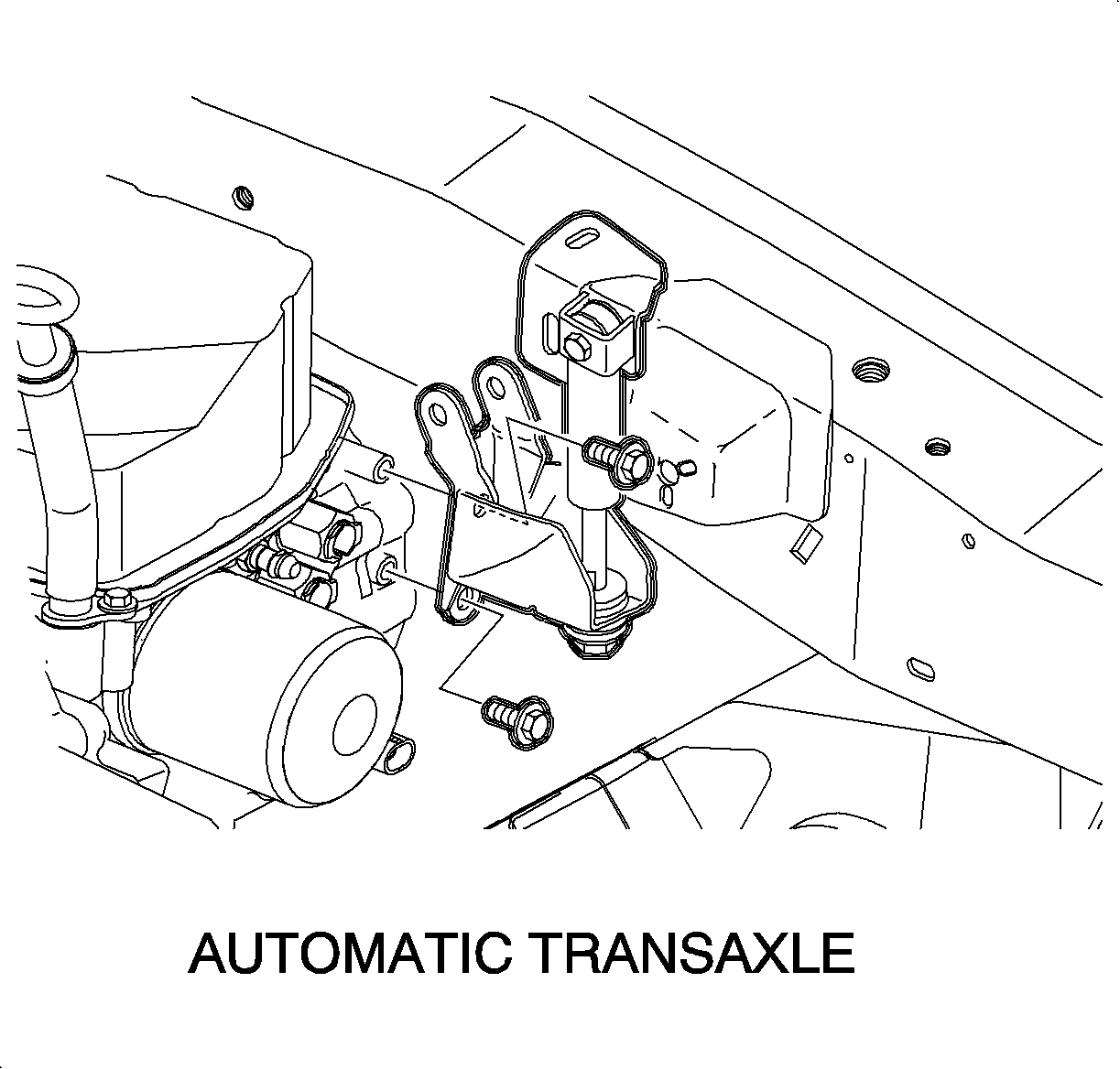
- Install bench-assembled damper kit by securing
it in place with the two transaxle strut bracket fasteners.
Tighten
Transaxle Strut Bracket-to-Transaxle Bolts: 54 N·m (40 lb ft)
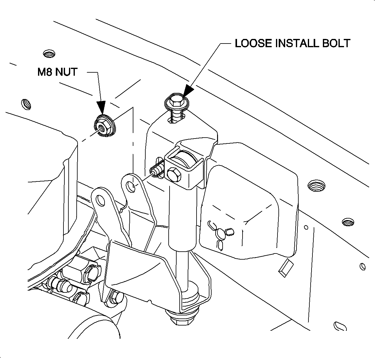
- Finger start forward vertical battery tray bolt
through the damper kit's upper bracket. Tighten loosely to secure bracket location
while making sure that the horizontal hole in the upper bracket aligns with its mating
hole in the midrail.
- Raise vehicle on a hoist.
- Remove left front wheel and tire assembly.
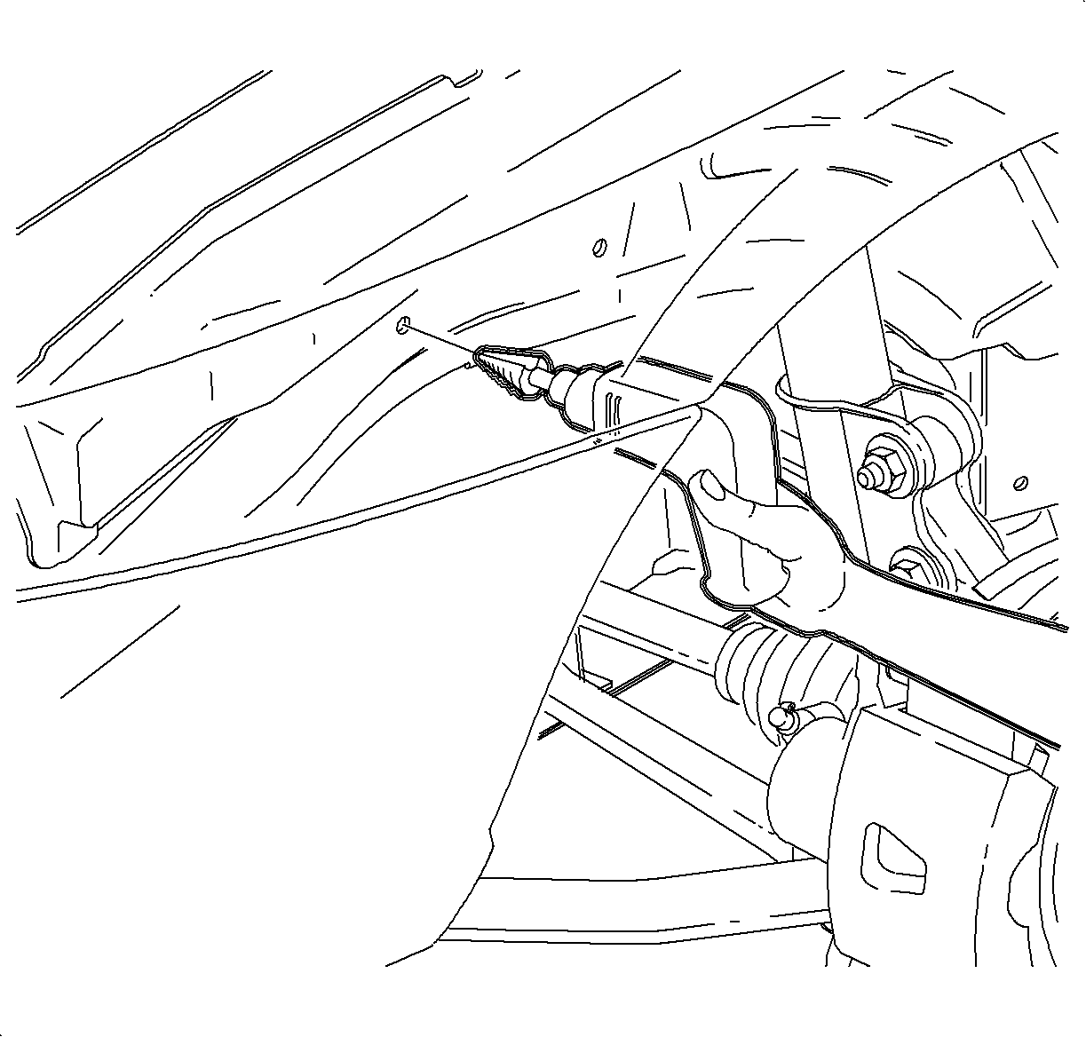
Important: The hole created in the next two steps will be used to gain access to the inside
of the frame rail for installation of the M8 x 20 mm bolt.
- Refer to illustration and locate the forward hole in frame rail that was used
in first design vehicles to secure battery tray tot he frame rail.
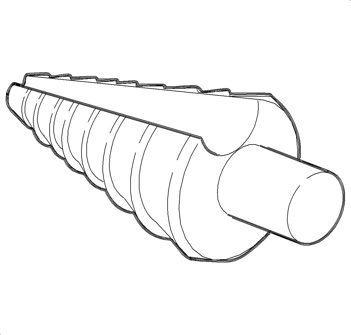
- Using a metric SAE dimension stepped uni-bit,
enlarge hole to 17 mm (11/16 in.)
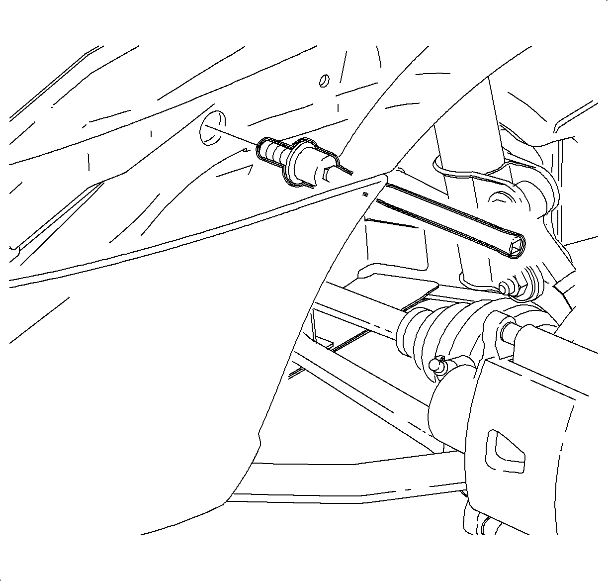
- To install M8 x 20 mm bolt, use an extension
and a 10 mm socket. Use a magnetic socket or secure the bolt in the socket with RTV.
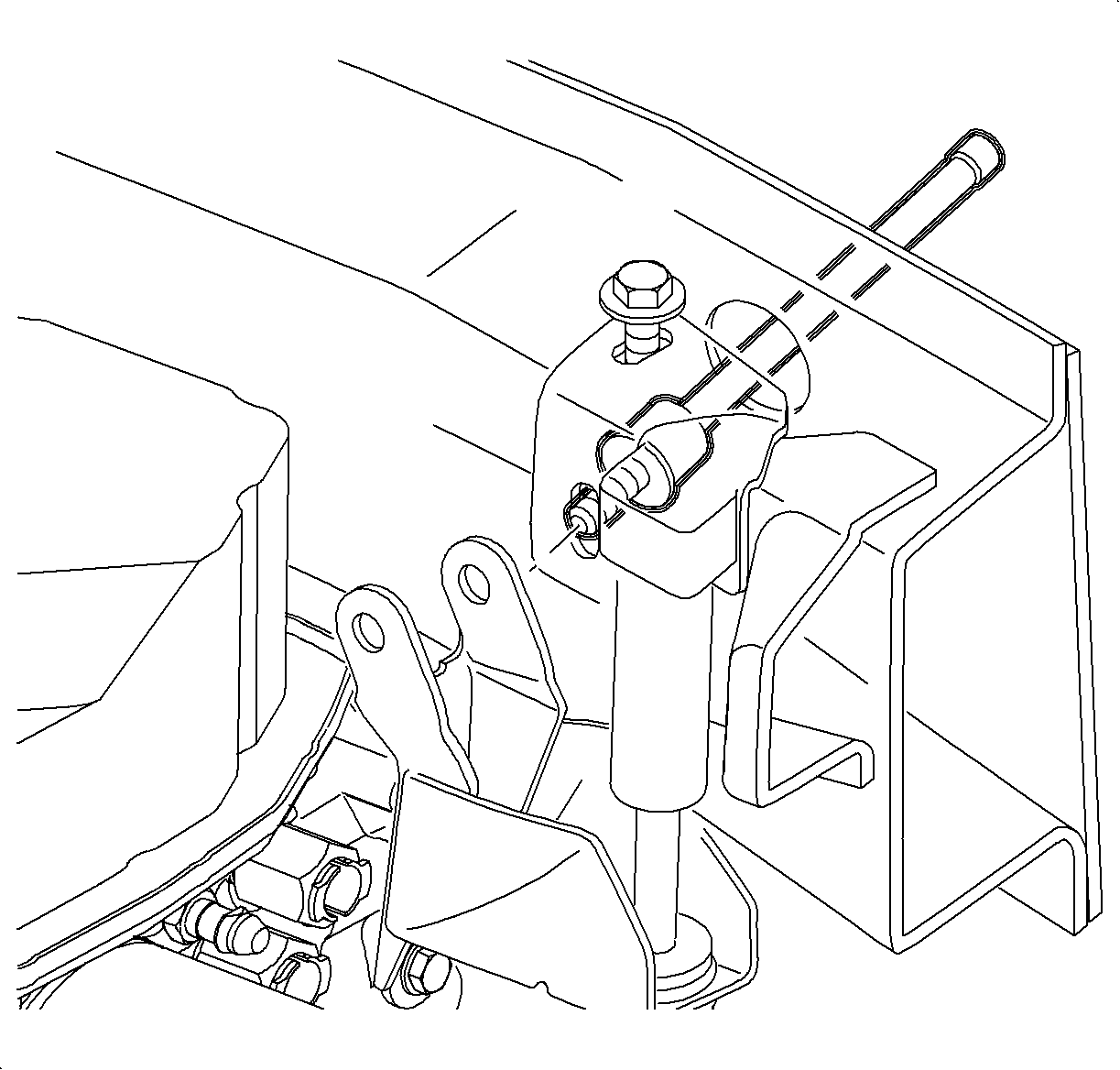
- Slide bolt, socket and extension through 17 mm
or 11/16 in. hole created in a previous step. Slide the bolt through the opposite
hole in the inside of the midrail and through the hole in the damper kit's upper bracket.

- Install M8 nut onto bolt and tighten.
Tighten
Damper Bracket--to-Frame Rail Fasteners: 30 N·m (22 lb ft)
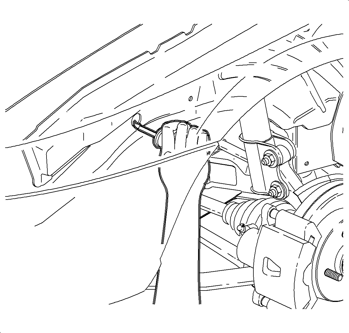
- Using 3M WINDO-WELD Primer (Black) (P/N
08643) or equivalent, prime edge of 17 mm, or 11/16 in. hole enlarged in outside of
midrail.
- Install Wheel and tire assembly.
Tighten
Torque: 140 N·m (103 lbs ft)
- Lower vehicle from hoist.
- Install transaxle strut to the new modified transaxle strut bracket.
Tighten
Transaxle Strut Bracket-to-Transaxle Bolts: 70 N·m (52 lb ft)
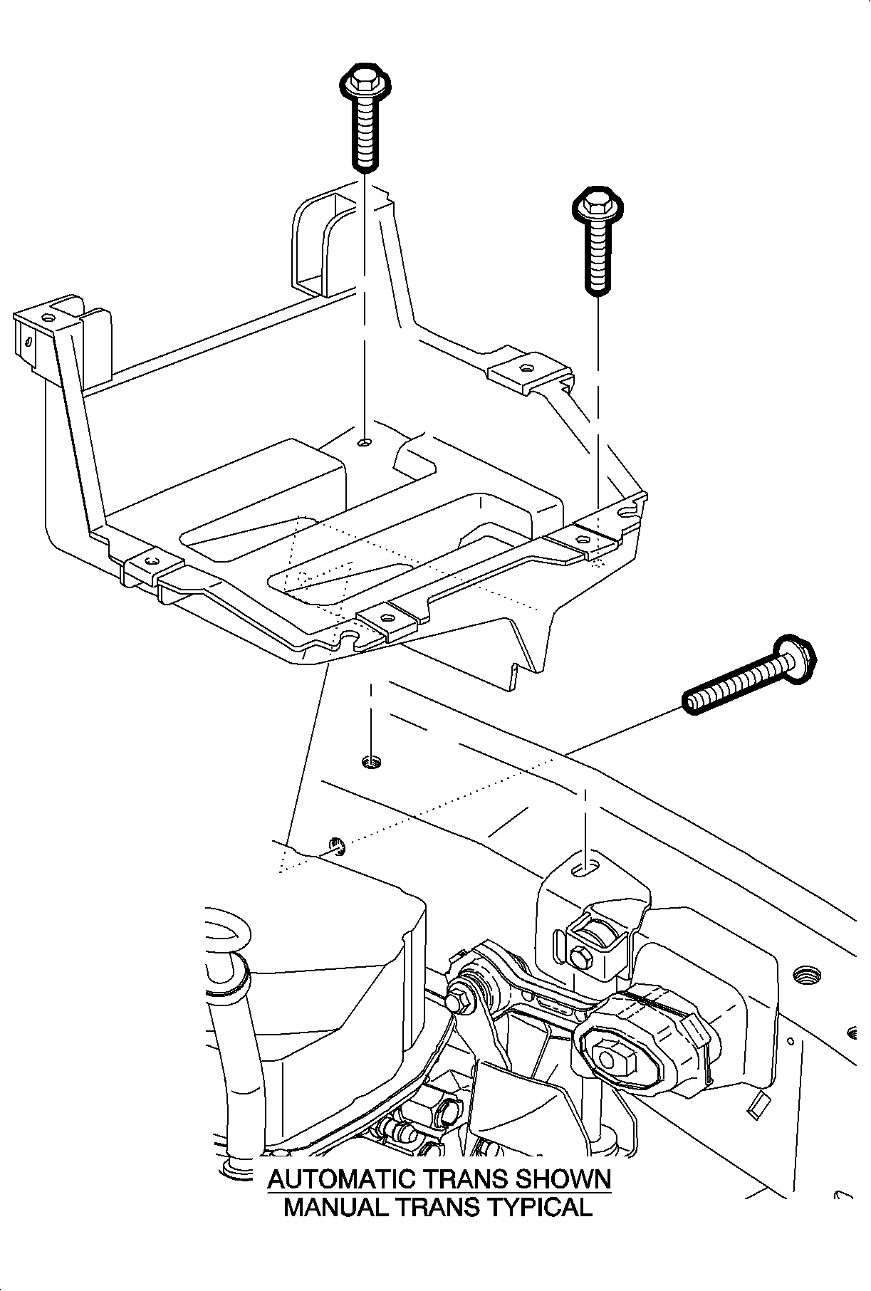
- Install battery tray and loosely install all
three battery tray bolts starting with horizontal bolt.
- Torque front vertical battery tray bolt.
Tighten
Battery Tray Bolt (Front Vertical): 20 N·m (15 lb ft)
- Torque rear vertical battery tray bolt.
Tighten
Battery Tray Bolt (Rear Vertical): 10 N·m (89 in lb)
- Torque horizontal battery tray bolt.
Tighten
Battery Tray Bolt (Horizontal): 10 N·m (89 in lb)
- Position PCM to battery tray and install bolts.
Tighten
PCM-to-Battery Tray Bolts: 6 N·m (53 in lbs)
Important: The damper-to-upper bracket bolt is properly torqued.
- Verify damper-to-upper bracket bolt is properly torqued.
Tighten
Damper-to-Upper Bracket: 70 N·m (52 lb ft)
- Install transaxle strut-to-frame rail bolt.
Tighten
Transaxle Strut-to-Frame Rail Bolt: 70 N·m (52 lb ft)
- Install battery.
| 28.1. | Make sure that the battery is in good physical condition (e.g., no cracks,
or obvious damage). |
| 28.2. | Make sure that battery terminals are clean. |
| 28.3. | Make sure the battery cable ends are clean. |
| 28.4. | Install battery carefully in the battery tray; make sure that the terminals
do not short against any metal during the installation. |
| 28.5. | Install battery hold down bracket. |
Tighten
Battery Hold Down Bracket Fasteners: 9 N·m (80 in lbs)
| 28.6. | Connect positive battery cable. |
Tighten
Battery Terminal Bolts: 17 N·m (13 lb ft)
| | Important: It may be necessary to use a 2 mm thick shim between the forward mounting foot
on air cleaner assembly and frame rail.
|
- Install air induction system.
- Road test vehicle to verify that vibration has been corrected.
Parts Requirements
21012637 Powertrain Damper Kit (Automatic Transaxle)
21012638 Powertrain Damper Kit (Manual Transaxle)
Claim Information
To receive credit for this repair during the warranty coverage period, submit
a claim through the Saturn Dealer System as follows:
Case
Type
| Description
| Labor
Operation
Code
| Time
|
VW
| Vehicle Vibration 48--54 mph - Install Powertrain Damper Kit (2000--2002 Vehicles)
| T9684
| 1.4 hrs
|


