PWM Output Circuit Malfunction

Circuit Description
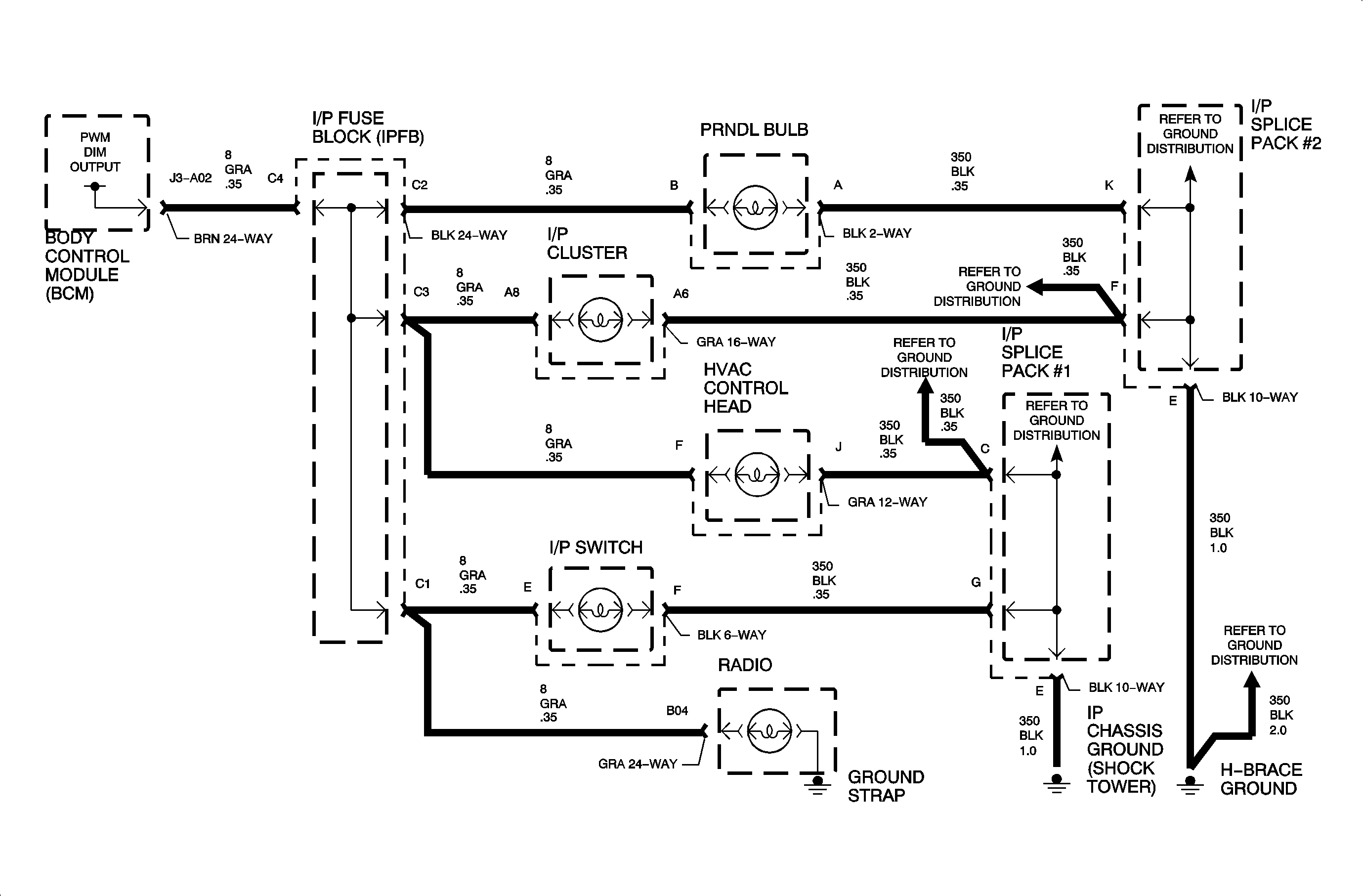
The dimmer output controls the intensity of the back-lighting of the cluster,
radio, I/P switch, HVAC control head, and the transmission range shifter assembly.
When the BCM receives the input voltage from the dimmer potentiometer over circuit
230 it converts it to a corresponding resistance value, and then to an output dimming
level on circuit 8.
The dim output pulse width modulated signal. Minimum dim pot input voltage corresponds
to maximum output duty cycle. Maximum dim pot voltage corresponds to minimum output
duty cycle.
The BCM also provides a Class II PWM dimming message which is
used by the IP cluster to provide dimming level control of the odometer backlight.
Conditions for Setting the DTC
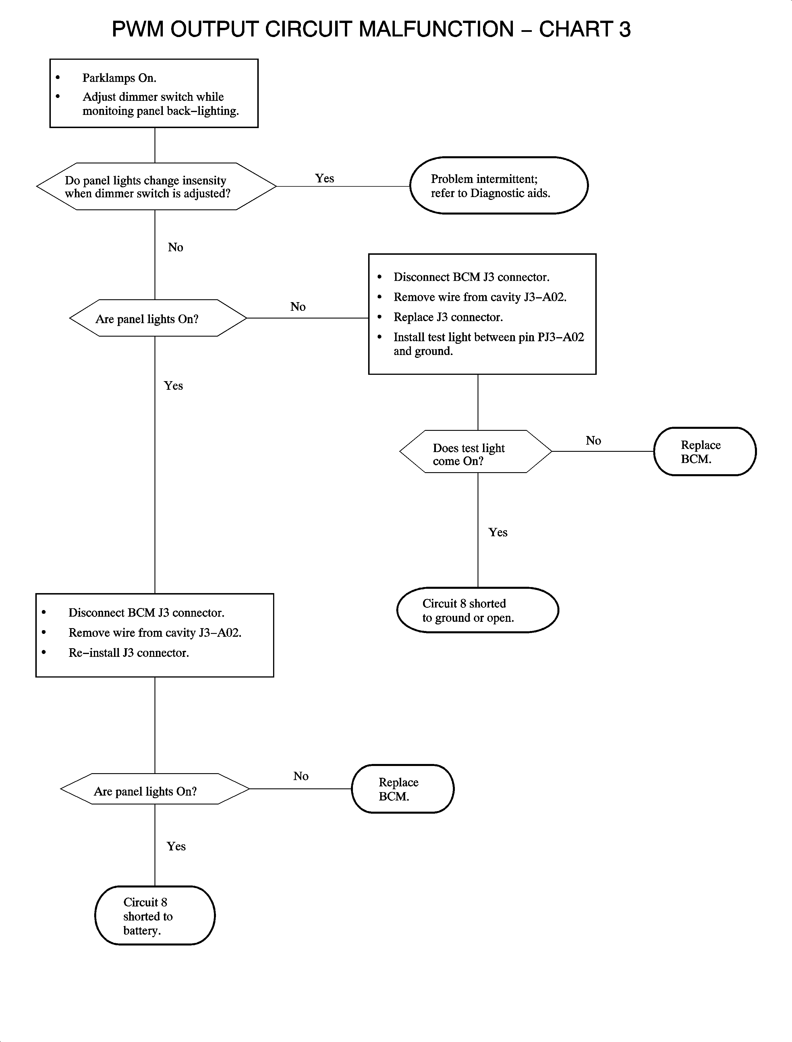
| • | Circuit 8 shorted to ground, battery, or open |
| • | Panel lamps are inoperative |
| • | Parklamps are On voltage |
| • | Condition exists for 1 second |
Diagnostic Aids
| • | Check for poor connection at the BCM. Inspect harness connectors for backed
out terminals, improper terminal mating, broken connector locks, improperly formed
or damaged terminals and poor terminal to wire connection (terminal crimped over wire
insulation and not conductors). Inspect wiring harness for damage. |
| • | If fault is suspected to be intermittent, wiggling harness wiring may
help in locating fault. |


