Knocking or Rattle Noise from Front of Vehicle During Deceleration

| Subject: | Knocking or Rattle Noise from Front of Vehicle During Deceleration (4000 RPM and Lower) (Replace Clutch Disc, Clutch Cover, and Machine a Chamfer into Flywheel). Due to changes in the service procedure, this bulletin supercedes 98-T-24, which should be discarded. |
| Models: | 1996-1998 Saturn vehicles built before and including VIN WZ305219 equipped with MP2 or MP3 manual transaxles |
Condition
Some customers may comment on a knocking or rattle type noise coming from the manual transaxle during moderate to heavy deceleration in any gear. The complaint is most noticeable when lifting off the throttle and decelerating from 4000 RPM and lower.
Note: If the gear rattle experienced does not match the symptoms as described above or the noise is not considered to be normal gear "mesh" noise, refer to diagnostics in the appropriate model year Manual Transaxle Service Manual. In these cases the long travel damper clutch disc will have no effect on eliminating or reducing these complaints.
Cause
The gear rattle is caused by insufficient dampening of engine pulsations by the clutch disc dampening springs. These pulsations allow the unloaded transaxle drive gears to knock against the driven gears. This knocking creates an audible "gear rattle."
Correction
To address this concern, a long travel damper clutch disc, (P/N 21120564), has been released. The new clutch disc is larger than the current disc (P/N 211020453). In order to allow clearance for the long travel damper clutch disc, the inner diameter of the clutch cover has been increased and the inside edge of the current flywheel must be chamfered. The part number of the new clutch cover is 21120582. When servicing a vehicle where it is necessary to replace the current clutch disc with the new long travel damper clutch disc, it is also necessary to machine a chamfer into the current flywheel and replace the original clutch cover (P/N 21120455) with new clutch cover (P/N 21120582).
Important: Prior to performing the following service procedure, check the vehicle service history to determine whether the flywheel has already been resurfaced. Due to clearance issues, a resurfaced flywheel and latest design disc are not compatible. The minimum flywheel thickness is 28.25 mm (1.11 in). Using a micrometer, measure flywheel thickness in three places around the circumference of flywheel. All measurements must be made at the same distance in from the edge of flywheel and at equal distances from each other. If the flywheel has been resurfaced previously or is less than 28.25 mm (1.11 in) in thickness and the clutch disc is being replaced with the long travel damper disc (P/N 21120564), it is necessary to replace the flywheel with chamfered flywheel (P/N 21120535).
Procedure
- Remove clutch cover, clutch disc, and flywheel according to procedures in the appropriate year Manual Transaxle Service Manual.
- Machine flywheel according to "Flywheel Machining" procedure listed in this bulletin.
- Install machined flywheel or new flywheel (P/N 21120535), new clutch disc (P/N 21120564), and new clutch cover (P/N 21120582) according to procedures in the appropriate year Manual Transaxle Service Manual.
Important: Failure to machine a chamfer on the current flywheel could create a noise concern in the transaxle as the clutch disc normally wears.
| • | A flywheel is a precision machined part. It must be properly machined to provide effective performance. The flywheel may be taken to a machine shop for machining, or may be machined at a Saturn retail facility using an adapter set on a brake lathe. |
| • | If your Saturn retail facility is equipped with an Accu-turn Brake Lathe, it is necessary to order an Accu-turn Flywheel Adapter Set. Call Dealer Equipment at (800) GM-TOOL (800 468-6657) to order an Accu-turn Flywheel Adapter Set (P/N 54-436057). |
| • | If your Saturn retail facility is equipped with an Ammco Brake Lathe, the accessories needed for creating a chamber on the flywheel should be included. The Ammco Brake Lathe offers no provision for measuring depth of cut. The depth of cut can be measured using a dial indicator. |
| • | If your Saturn retail facility is equipped with a brake lathe other than the two manufactures mentioned above, contact that manufacturer's representative for the necessary flywheel machining accessories. |
Important: During clutch installation, install flywheel on crankshaft and start bolts. Torque flywheel bolts in a crisis-cross pattern as shown in the illustration below.
Tighten
Tighten nut to 80 N·m (59 lb ft)
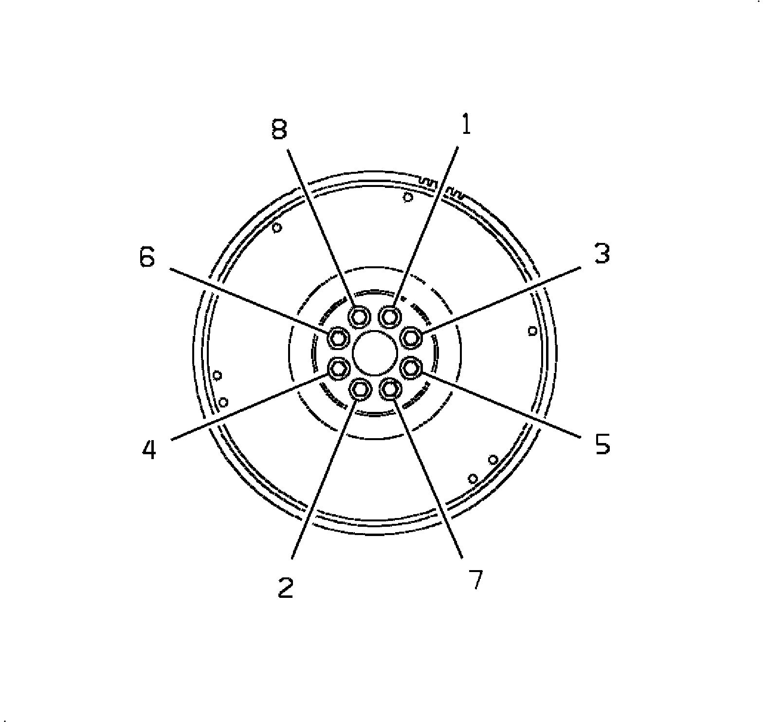
Notice: When tightening the clutch housing cover assembly bolts, do not tighten any one bolt more than a half turn at a time or the clutch housing cover assembly may warp.
Flywheel Machining
- Measure and mark the flywheel in the area to be machined. Measure 60 mm-64 mm (2.4 -2.5 in.) starting from the outside edge of the flat portion of the flywheel moving towards the inside edge of the flywheel The material to be removed is from the inside edge of the flywheel. The material to be removed is from the inside edge of the flywheel to the measured mark.
- For Ammco lathes: Rotate the lathe spindle hand wheel clockwise (right) to the end of its travel. Then rotate the spindle hand wheel clockwise (left) approximately 2-1/2 turns. Mount the flywheel onto the arbor with the clutch side towards the lathe. Slide the centering cone (#3903) with the taper towards the flywheel onto the arbor. Next, slide the centering cone spring (#3110) and hub-less adapter (# 9489) onto the harbor. Use double taper adapters (# 9193 and # 9124), as well as the self-aligning spacer (# 9492) to space out the arbor.
- Use the largest possible "spacers" to fill out the arbor and allow the arbor clamp nut to mount.
- Wrench tighten the arbor clamp nut* counterclockwise until the flywheel and adapters begin to turn on the arbor. Then continue to advance the wrench 1/6 of a turn.
- For Ammco lathes: rotate the lathe cross feed hand wheel inward (clockwise/right) to its end of travel. Then rotate the cross feed hand wheel approximately 8 turns out (counter-clockwise/left). Lock knob at bottom of guide bar.
- Position the tool bit holder onto the boring bar. Male sure the tool bit holder is flush in boring bar slot. The slot must be clean to ensure correct slot angle. Tighten the square head screw(s).
- Position the boring bar by loosening the boring bar clamp nut and sliding the boring bar inward toward the flywheel until the cutting tip is close to measured mark.
- Check the boring bar cutting tip for excessive wear or damage and replace if necessary. Always use a cutting tip recommended by the lathe's manufacturer.
- Angle the cutting tip so that it is approximately 30 degrees to the flywheel. To aid in this procedure, use a protractor to cut out a template similar to one shown and align it to the carbide tool bit.
- To achieve the best cutting position, the entire boring bar clamp may be swiveled. To optimize lathe performance, minimize the boring bar length while still being able to reach the flywheel.
- Tighten the stud nut.
- Start the lathe.
- Remove necessary metal from flywheel:
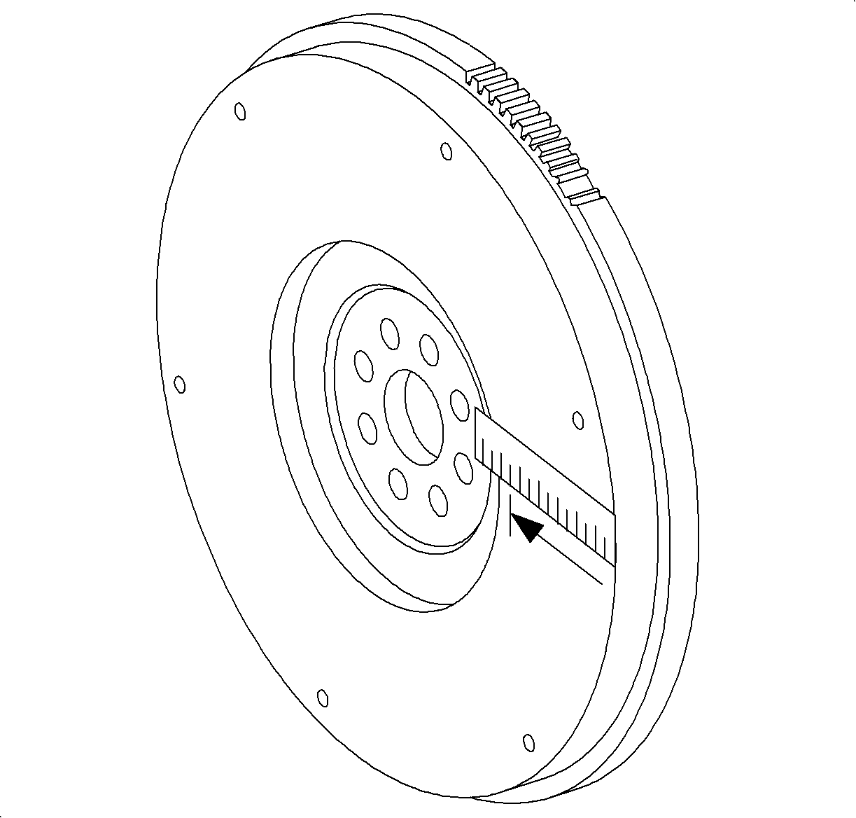
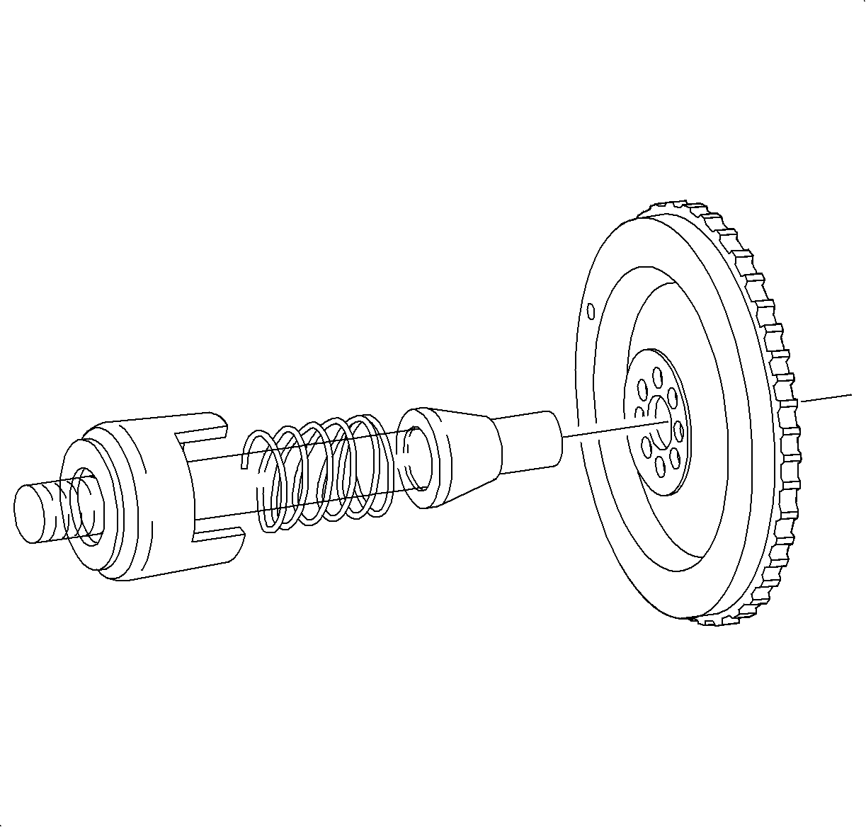
Important: The flywheel is centered on the alignment cone chamfer.
Important: Both surfaces of the inside bell clamp must be parallel or the flywheel will not turn on a parallel plane with the cutting tip. Even the smallest nick, scratch, or loose chip on the mating surfaces can cause incorrect flywheel mounting alignment. This will cause inaccurate machining. Always inspect the surface of each bell clamp. Wipe each part clean before and after using it. If a bell clamp is dropped or damaged, contact dealer equipment or the manufacturer to obtain a new bell clamp.
For Accu-turn™ lathes: Using contents found in the flywheel adapter set, mount the first bell clamp, alignment spring, washer, alignment cone, flywheel and second bell clamp onto the lathe arbor.Important: Do not overtighten the arbor clamp nut.
*Use deep side of nut on Ammco lathes manufactured after, 1996. (Arbor is 1 inch longer)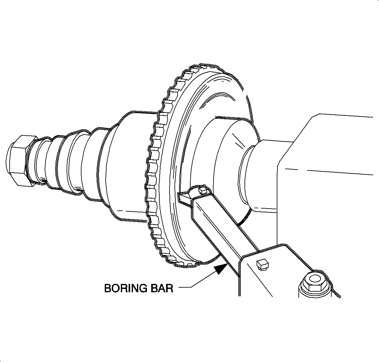
Important: For Accu-turn™ lathes: replace the short right hand tool holder in the boring bar with the left hand tool holder from the twin cutter.
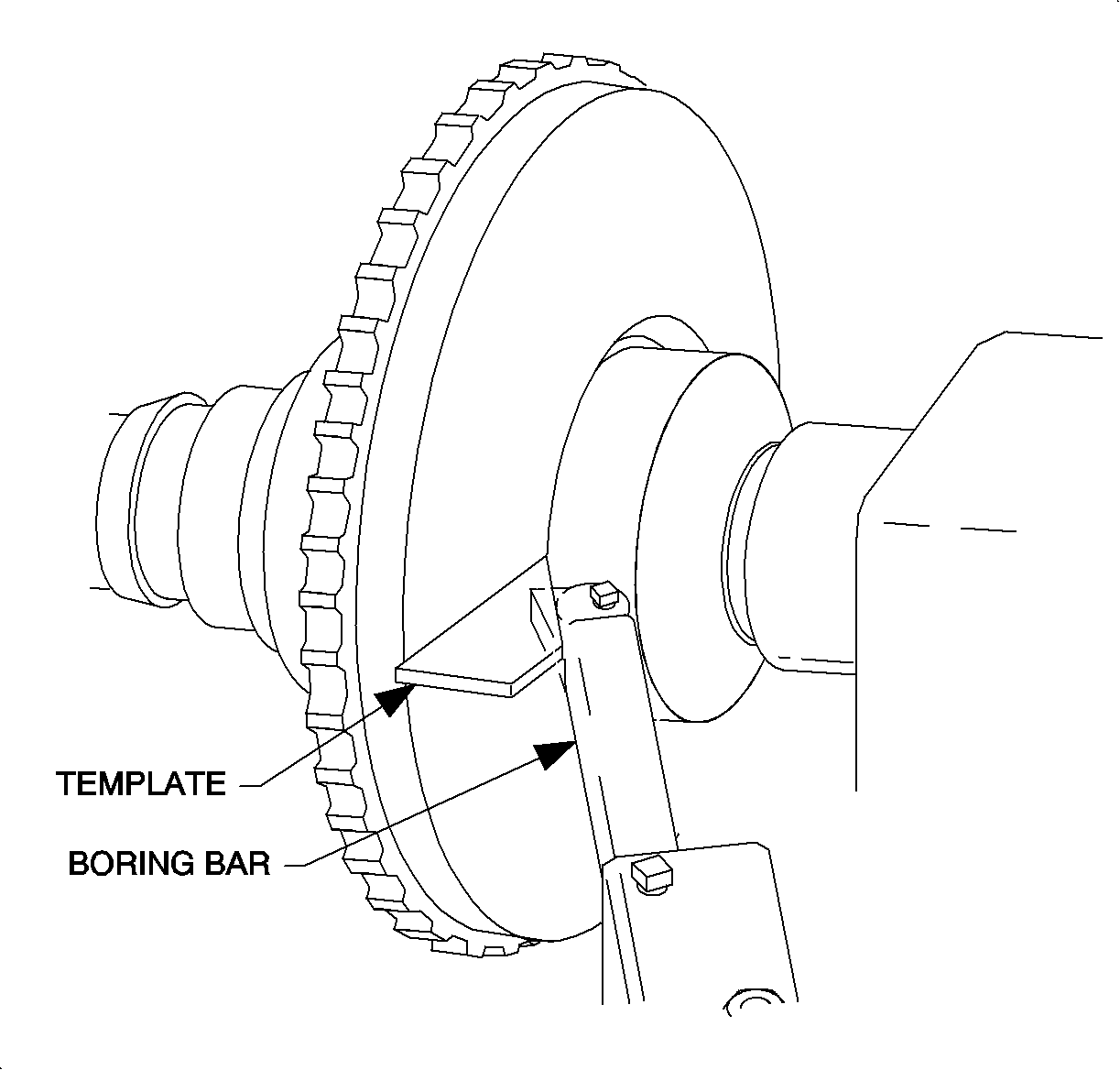
| 9.1. | Adjust the arbor bar so that the carbide bit contacts the inside edge of the flywheel. |
| 9.2. | Position the carbide and boring bit over the inside edge of the flywheel so that the edge will contact the bit in the middle of its leading side. |
| 9.3. | Adjust the bit so that it is positioned 30 degrees to the flywheel. |
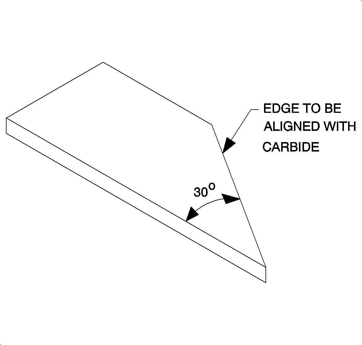
Tighten
Tighten nut to 34 N·m (25 lb ft)
Important: Auto feed functions must not be used for this procedure.
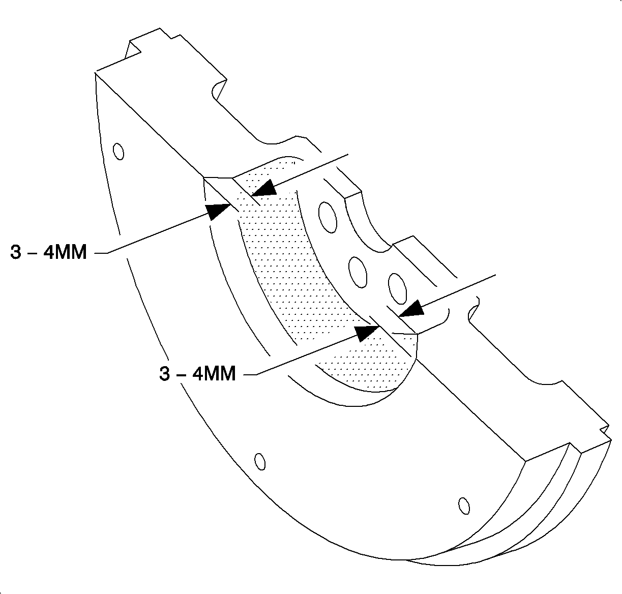
- Total depth of cut should be 3-4 mm (.12 -- .46 in.).
For Ammco lathes:
- Turning the spindle handwheel to the right increases depths of cut.
- Turning the cross feed handwheel outward moves the tooling across the flywheel.
For Accu-turn lathes:
- Turning the drum feed handwheel clockwise increases depth of cut.
- Turning the rotor feed handwheel counter-clockwise moves the tooling across the flywheel.
Inspection After Flywheel Machining
Surface Finish
The surface of the inside edge of the flywheel after the chamfer is cut will likely be of lessor quality than the flywheel face. The chamfer may include slight signs of chatter marks. This is an acceptable finish since this chamfer is only intended to provide clearance for the clutch disc and not for a frictional surface finish.
Surface Regularity
The face of the chamfered surface may very slightly in thickness. This is acceptable if the depth of the chamfer is within the 3-4 mm (.12 -.16 in.) range as specified in the above procedure.
Notes:
| • | All contact surfaces of the lathe adapters, lathe arbor and flywheel must be clan and free of nicks and burns. |
| • | Depth of cut can be aided by a dial indicator. |
| DISCLAIMER: We believe these sources and their equipment to be reliable. There may be additional manufacturers of such equipment. Saturn does not endorse, indicate any preference for, or assume any responsibility for the product or equipment from this firm, or for any such items which may be available from other sources. |
Parts Requirements
21120535 | Asm-Flywheel |
21120564 | Plate Asm- Clutch Driven |
21120562 | Cover Asm-Clutch Housing |
ADDITIONAL ITEMS: A protector will be needed to create a template
Claim Information
To receive credit for this repair during the warranty coverage period, submit a claim through the Saturn Dealer System as follows:
Case Type | Description | Labor Operation Code | Time |
VW | Disc and/or Clutch cover, Clutch -Replace | K0800 | 5.0 hrs |
Add: | To Machine Flywheel (Includes Flywheel R) | 0.7 hrs |
