Removal Procedure
- Remove the fuel tank and fuel pump module.
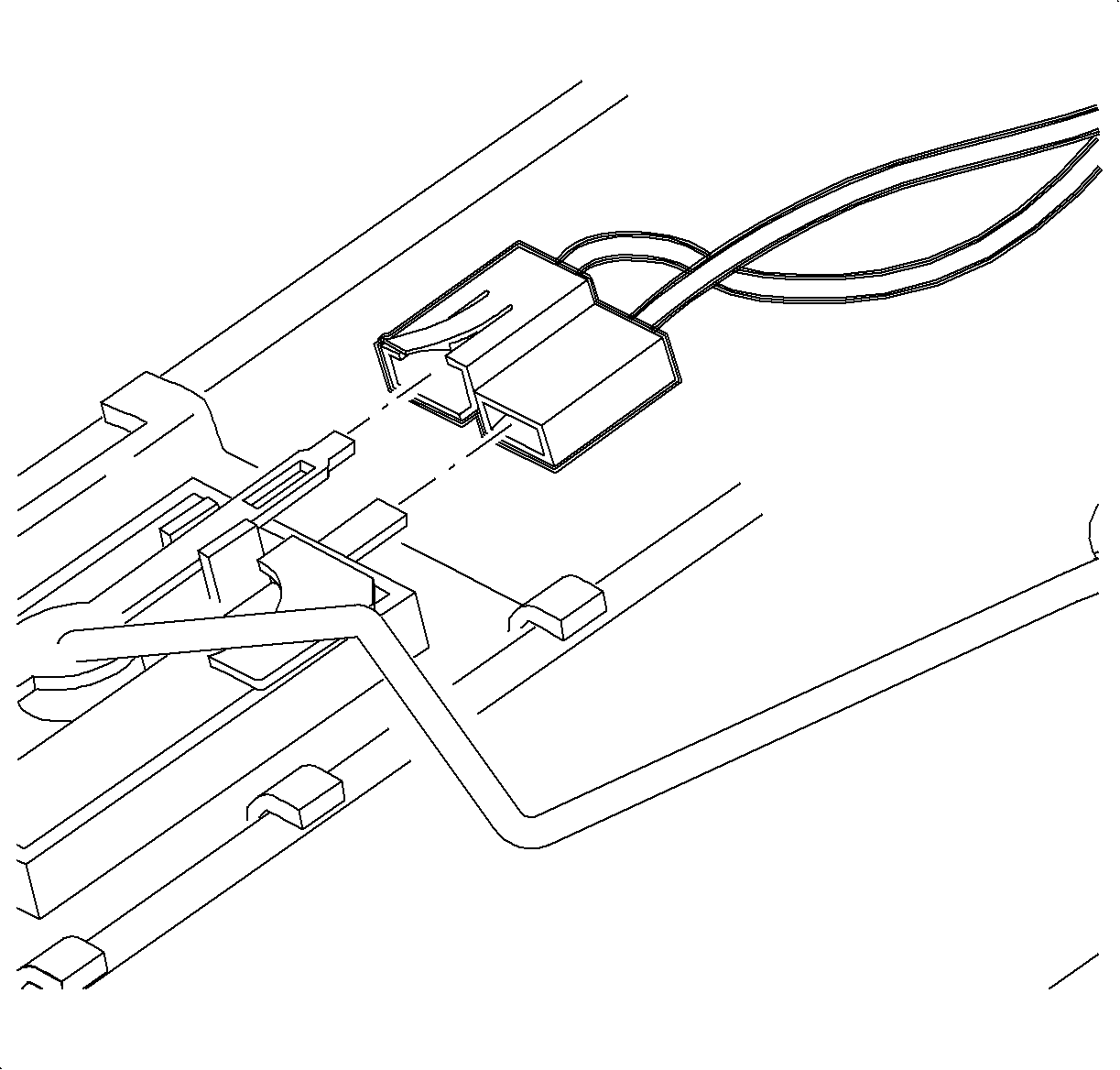
- Remove the electrical connector from the fuel level sending unit by disengaging the locking tab and pulling the connector from the sender.
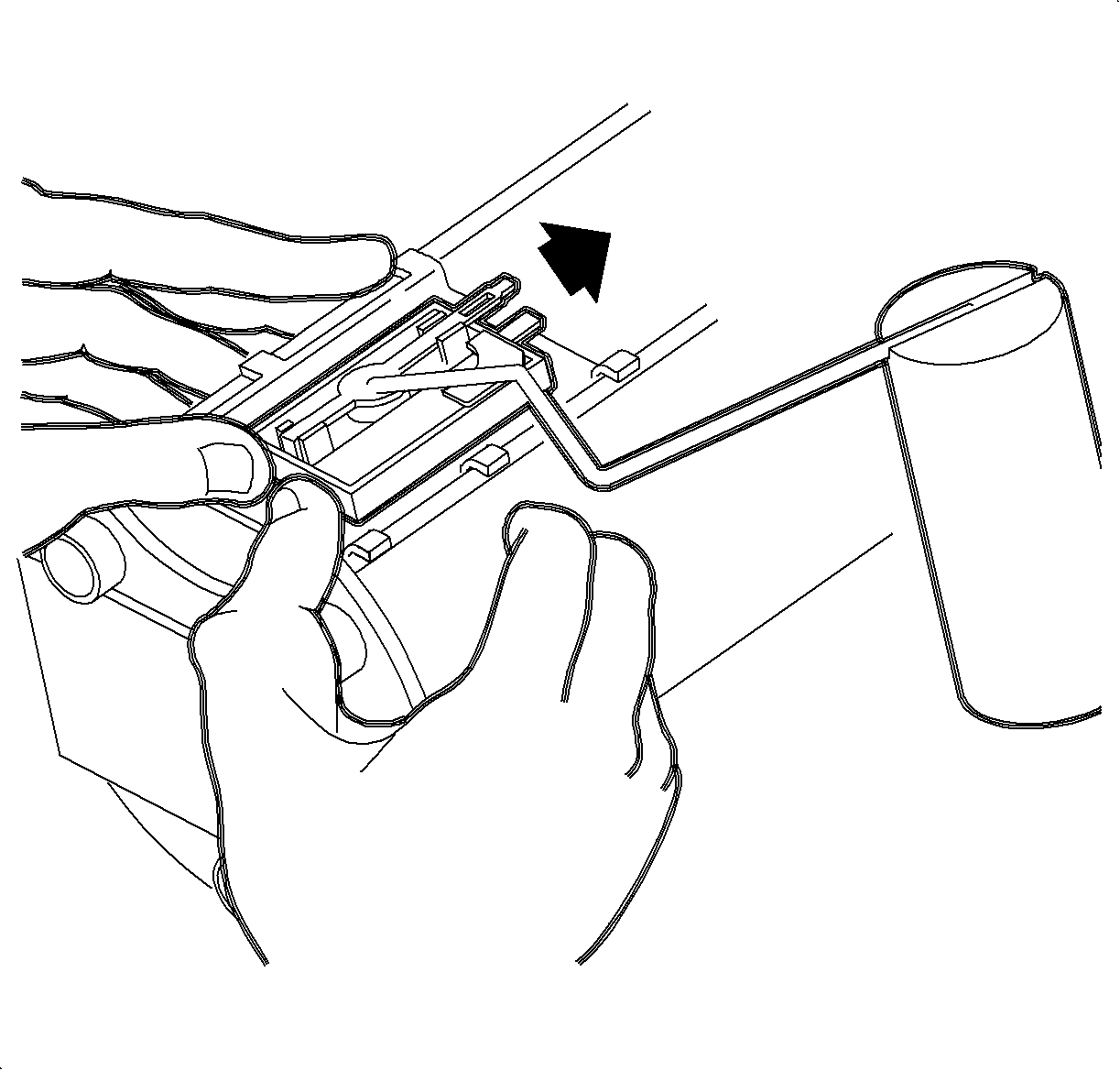
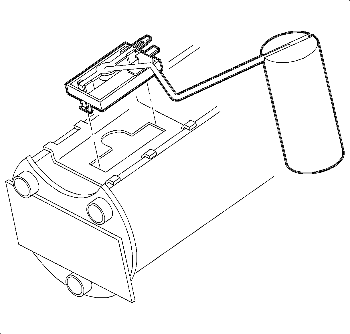
- Grasping the fuel pump module in both hands and placing both thumbs at the bottom of the fuel sending unit, firmly press the sender toward the top of the module to disengage the bottom attachment tang.

Caution: Do not allow smoking or the use of open flames in the area where work on the fuel or EVAP system is taking place. Anytime work is being done on the fuel system, disconnect the negative battery cable, except for those tests where battery voltage is required.

Important: The fuel pump assembly is only serviced as a module without the sender unit. The inlet filter can be cleaned with mineral spirits, however, it cannot be replaced.
Important: The fuel pump module to tank seal must always be replaced whenever the module is removed from the fuel tank. The correct seal is green in color. Do not use the older black seal.
Installation Procedure
- Position the sender unit tank in the locator slot and snap the unit into place.
- Install the electrical connector from the pump module to the sender unit. Push firmly to engage.
- Install the fuel pump module and tank.
- Perform the Service Bay Diagnostic Test for the evaporative emission system using the Tech-2. This test will verify the integrity of the vapor handling areas of the fuel system. Refer to Service Stall System (SSS) user guide.

Important: Verify that the float arm on the sender unit maintains the correct relationship to the pump module by standing the module on a flat, horizontal surface and measuring the distance between the surface and the bottom of the float. Use a 5/32 in. diameter drill as a gage. The gage must freely pass between the float and the horizontal surface with no more than 1/16 in. clearance. Refer to Fuel Sender Assembly Replacement .
To verify the function and calibration of the sending unit, refer to "Fuel Gage and Tank Sender Unit Calibration and Electrical Circuit" in this service manual.