Removal Procedure
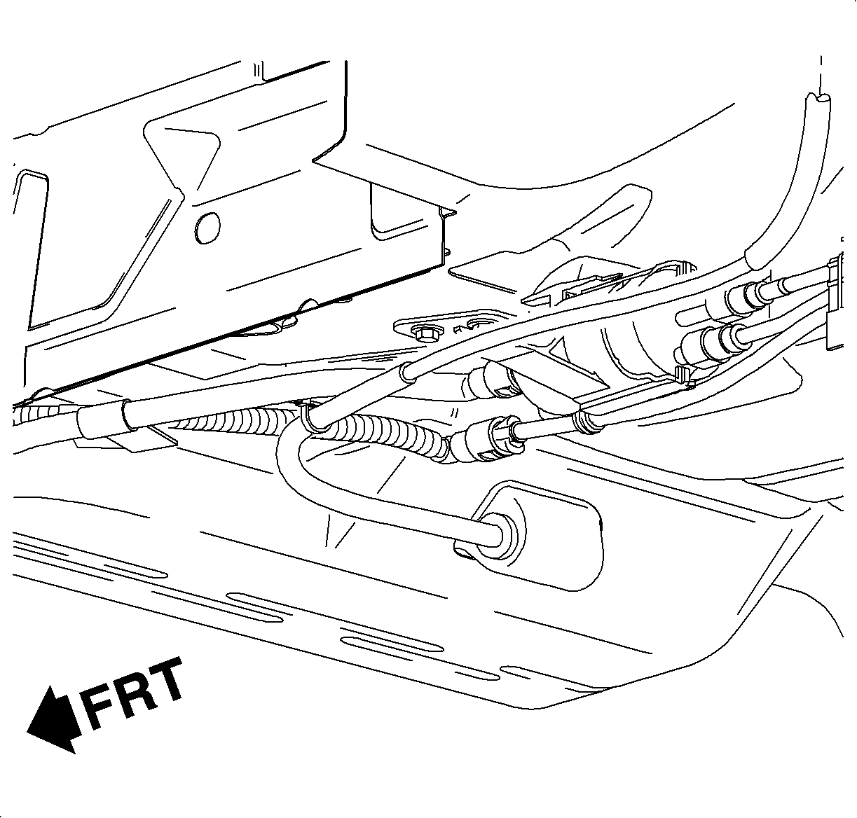
The fuel filter/pressure regulator is located on the underbody at the forward edge of the left-side of the fuel tank.
- Position on a hoist.
- Disconnect the negative battery cable.
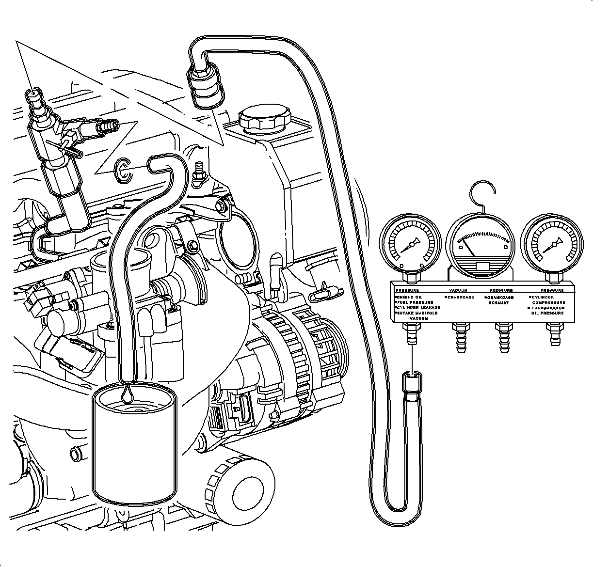
- Relieve the pressure in the fuel system at the fuel pressure test port. Refer to Fuel Pressure Relief .
- Raise the vehicle to a comfortable working height.
- Remove the 2 fuel filter/pressure regulator bracket screws (10 mm hex).
- Unlatch the fuel line bundle retaining clip on the left-side of the fuel tank.
- Disconnect the evaporative emission (EVAP) purge line at the 90 degree quick connect.
- Slide the outlet of the filter/regulator out of the support on the fuel tank bracket and remove the fuel feed line at the 90 degree quick connect.
- Pivot the filter/regulator down while moving the leg of mounting bracket out from under the chassis brake lines.
- Disconnect the fuel feed and return lines at their quick connect fittings on the filter/regulator.

Caution: Fuel supply lines will remain pressurized for long periods of time after the engine is shutdown. This pressure must be relieved before servicing the fuel system.
Caution: Ensure that the vehicle is properly supported and squarely positioned. To help avoid personal injury when a vehicle is on a hoist, provide additional support for the vehicle on the opposite end from which the components are being removed.


Notice: Take care not to damage the retaining clip when opening it. The fuel lines must be retained in this clip, and if damaged, the fuel tank assembly must be replaced since the retaining clip is not serviced separately.
Caution: Whenever fuel line fittings are loosened or removed, wrap a shop cloth around the fitting and have an approved container available to collect any fuel.
Important: It is not necessary to remove the filter/regulator from the bracket. Both items are serviced as an assembly.
Installation Procedure
- Install the 3 new fuel line retainers into the female portion of the quick connect fuel line fittings.
- Install the fuel feed and fuel return lines onto the filter/regulator.
- Place the fuel feed, return, and EVAP purge lines into the fuel tank retainer clip.
- Slide the leg of the filter/regulator bracket under the chassis brake lines and pivot the filter/regulator up.
- Install the 90 degree fuel feed line quick connect on the filter/regulator outlet.
- Connect the 90 degree EVAP purge line quick connect to the purge line.
- Place the fuel feed outlet pipe of the filter/regulator into the clip on the fuel tank bracket.
- Install 2 filter/regulator bracket attachment screws, 10 mm hex.
- Connect the negative battery cable.
- Energize the fuel pump and check for leaks at the filter/regulator.
- Perform the Service Bay Diagnostic Test for the evaporative emission system using the scan tool. This test will verify the integrity of the vapor handling areas of the fuel system. Refer to Service Stall System (SSS) user guide.
Notice: Replace plastic fuel line retainers whenever the fuel supply or return line is disconnected at the fuel rail. Install the new retainer into the female cavity of the connection. Care must be taken to ensure that the locking tab is centered in the window of the female cavity. Firmly press the female connection onto the male end until a click is heard, then pull back to confirm engagement. Pinched, kinked, or damaged fuel lines must be replaced.
Important: Lubricate the male ends of the filter/regulator with clean engine oil to ease installation and snap closed.

Notice: Refer to Fastener Notice in the Preface section.
Important: Ensure the chassis fuel feed and purge lines are routed on top of the emergency brake cable. The emergency brake cable must be secured firmly to the underbody to support the fuel and purge lines.
Tighten
Tighten the fuel filter/pressure regulator-to-frame rail to 8 N·m
(17 lb in).
Tighten
Tighten the battery terminal bolts to 17 N·m (13 lb ft).
