For 1990-2009 cars only
Removal Procedure
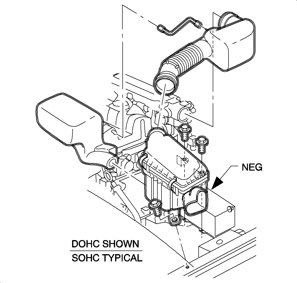
- Remove the air induction system.
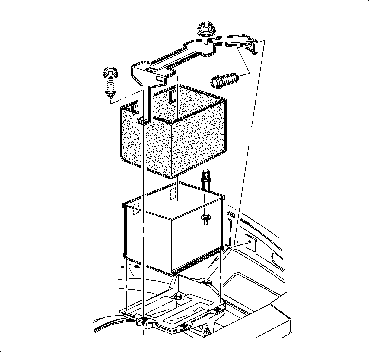
- Remove the battery.
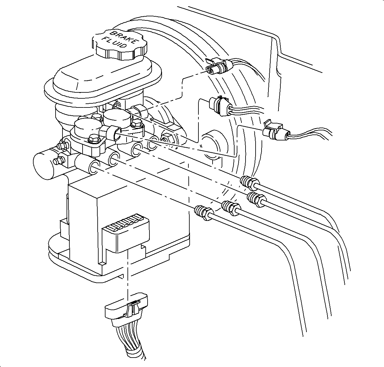
- Disconnect 2 electrical connectors from solenoid valves.
- Disconnect brake fluid level switch connector.
- Remove connector position assurance (CPA) retainer from six-way motor pack electrical connector.
- Disconnect 6-way electrical connector from motor pack.
- Disconnect brake pipe nuts from modulator.
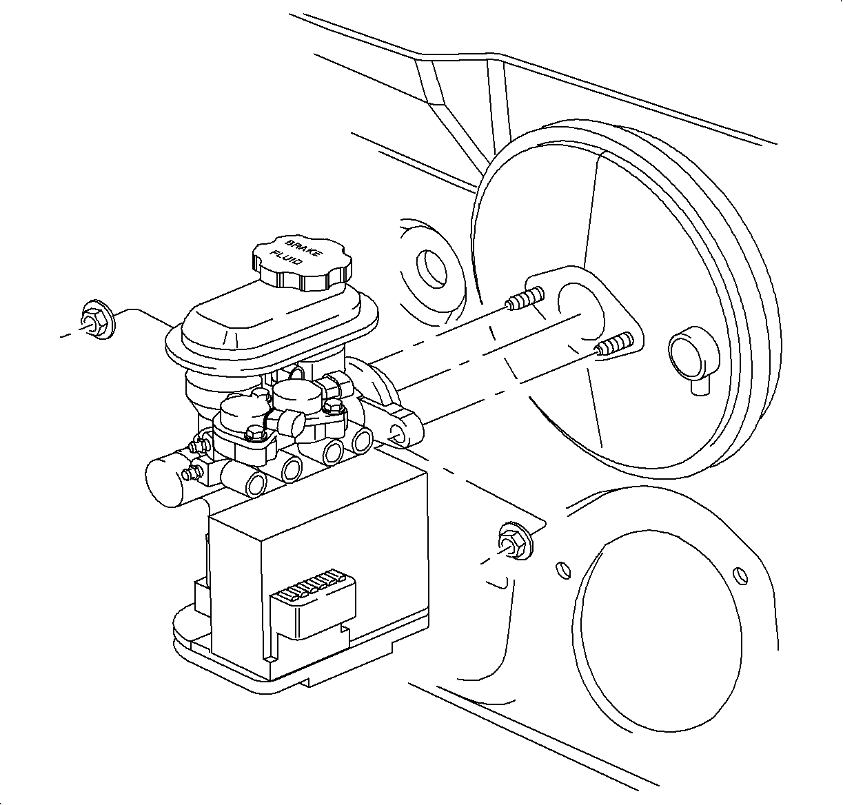
- Remove 2 brake control assembly to brake booster attachment nuts.
- Remove brake control assembly.


Important: Place a shop cloth on top of motor pack assembly to catch any dripping brake fluid.
Notice: Plug open brake pipes to prevent brake fluid loss and contamination.
Important: After removing brake pipe nuts, do not excessively pull or bend brake pipes away from brake control assembly.

Installation Procedure
- Position brake control assembly onto brake booster studs and install fastening nuts.
- Position brake lines into the brake control assembly and secure brake pipe nuts.
- Install 6 pin electrical connector onto motor pack assembly.
- Check to be sure that connector is fully seated and install CPA retainer.
- Install electrical connector onto brake fluid level switch.
- Install 2 electrical connectors onto solenoid valve.
- Install the battery.
- Install the air induction system.
- Fill brake fluid reservoir with clean brake fluid up to the base of the reservoir filler neck.
- Bleed brake system as specified.
- Check brake fluid level.

Tighten
Tighten brake booster studs to: 27 N·m (20 lb ft)

Important: Be careful not to bend brake pipes.


