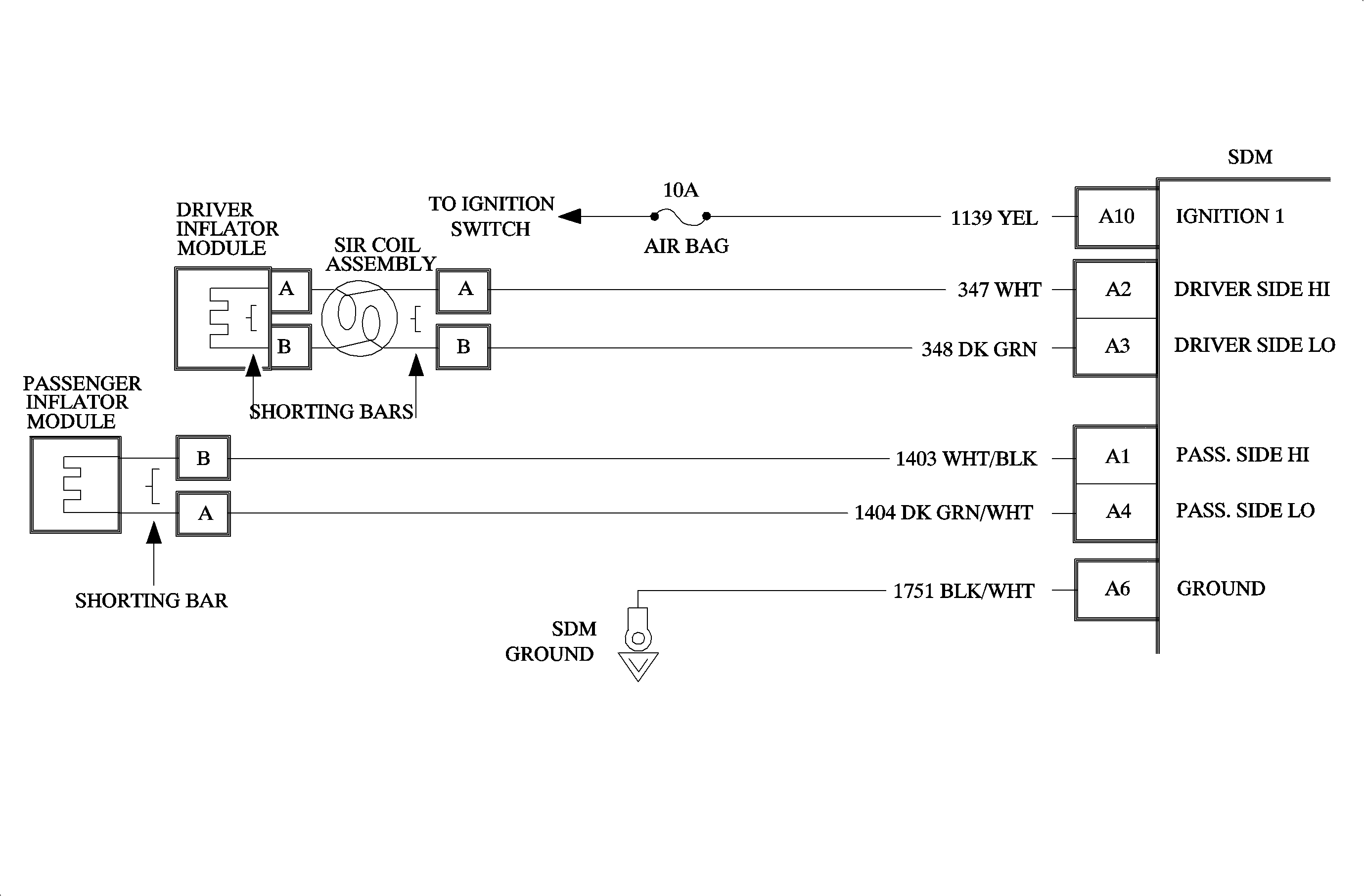
Circuit Description
When the ignition switch is first turned ON, the SDM will perform tests to diagnose critical malfunctions within itself. Upon passing these tests "Ignition 1", VLR, and deployment loop voltages are measured to ensure they are within their respective normal voltage ranges. Then SDM then proceeds with the "Current Source Diagnostics". "Driver Side LO" terminal A3 is grounded through a resistor and the driver current source connected to "Driver Side HI" terminal A2 allows a known amount of current to flow. By monitoring the voltage difference between "Driver Side HI" and "Driver Side LO" the SDM calculates the combined resistance of the driver inflator module, SIR coil assembly, harness wiring circuits 347 and 348 and connector terminal contact.
DTC Will Set When
The combined resistance of the driver inflator module, harness wiring circuits 347 and 348 and connector terminal contact is less than 1.2 ohms. This test is run once each ignition cycle during the "Current Source Diagnostics" when:
| • | No "higher priority faults" are detected during "Turn-On." |
| • | No "higher priority faults" are detected during "Continuous Monitoring" |
| • | "Ignition 1" voltage is above a specified value |
Action Taken
SDM turns ON the AIR BAG telltale lamp and sets, DTC B1022.
DTC Will Clear When
The malfunction is no longer occurring and the ignition switch is turned OFF, or a Scan Tool "Clear Codes" command is issued.
Diagnostic Aids
An intermittent condition is likely to be caused by a short between circuits 347 and 348, 1403 or 1404 or a malfunctioning shorting bar on the driver inflator module or SIR coil assembly which would require replacement of the component. The test for this DTC is only run while the AIR BAG tell tale lamp is performing the bulb check, unless DTC B1017 or DTC B1026 is detected. When a Scan tool "Clear Codes" command is issued and the malfunction is still present, the DTC will not reappear until the next ignition cycle.
When measurements are requested in this chart use SA 91114NE DVM with correct terminal adapter from SA 9206Z. When a check for proper connection is requested refer to Intermittent and Poor Connections. When a wire connector or terminal repair is requested, use the proper repair parts and refer to Wiring Repairs .
DTC Chart Test Description
The numbers below refer to the step numbers on the diagnostic table.
-
DTC B1016 and DTC B1022 will set simultaneously when the " Driver Side HI" circuit is shorted to the "Passenger Side HI" circuit due to parallel current paths.
-
This test determines whether the malfunction is in the driver inflator module circuitry or in the SDM wiring harness circuitry.
-
This test checks for a short from the "Driver Side HI" circuits to the Driver Side LO" circuit.
-
This test determines whether the malfunction is in the driver inflator module or the SIR coil assembly.
-
This test checks for a short from the "Driver Side HI" circuit to the "Passenger Side LO" circuit.
Step | Action | Yes | No |
|---|---|---|---|
1 | Did you perform the Diagnostic System Check - SIR? | Go to Step 2 | |
2 | Is Code B1016 also current? | Go to Step 3 | Go to Step 4 |
3 |
Go to Step 12 | Go to Step 5 | Go to Step 6 |
4 |
Is DTC B1022 present? | Go to Step 5 | Go to Step 6 |
5 |
Does DVM display OL (Infinite)? | Go to Step 7 | Go to Step 8 |
6 |
Does DVM display OL (Infinite)? | Go to Step 9 | Go to Step 10 |
7 | Measure resistance on SDM harness connector from terminal A2 to terminal A4. Does DVM display OL (Infinite)? | Go to Chart A | Go to Step 11 |
8 | Repair short from circuit 347 to circuit 348. Go to Step 12 | -- | -- |
9 |
Go to Step 12 | -- | -- |
10 |
Go to Step 12 | -- | -- |
11 | Repair short from circuit 347 to circuit 1404. Go to Step 12 | -- | -- |
12 |
Repeat SIR Diagnostic System Check. | -- | -- |
