Circuit Description

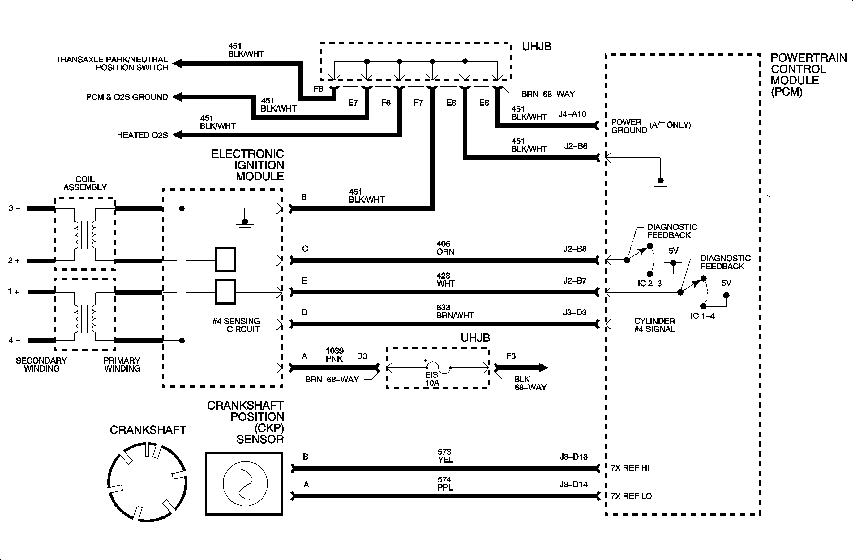
The PCM uses pulses from the crankshaft position sensor to determine the position
and RPM of the engine at various degrees of rotation. The PCM can then base misfire
diagnostics on the principle that crankshaft velocity will increase as each cylinder
contributes its power input. Under certain conditions the PCM will perform a series
of tests to determine misfire percentage on a cylinder based on crankshaft velocity
variation. The MIL, service engine soon, light will flash if an active catalyst damaging
misfire occurs (20-100 percent) and will illuminate ON solid if an emission
related misfire (2-19 percent) is present after 2 consecutive
trips. The MIL, service engine soon, light will turn OFF after 3 consecutive
passed trips meeting the same misfire criteria or 80 passed trips if the criteria
has not been met.
Conditions for Setting the DTC
Important: The misfire diagnostics are continually checked
with the engine running when the following conditions have been met.
DTC P0300 will set if random misfires have been detected after a series of tests
when:
| • | Engine speed is between 469-7,188 RPM. |
| • | Traction control fuel cut-off is not active. |
| • | Engine coolant is between -6.75 to +118°C (20-244°F). |
| • | Throttle change is not rapid. |
| • | The vehicle is not in decel fuel cut-off mode (DFCO). |
| • | Ignition voltage is between 8-15 volts. |
| • | No TP sensor, CKP, IAT, MAP, or ECT DTCs have been set. |
Diagnostic Aids
Verify the crank learned procedure has matched the PCM to the crankshaft in
the vehicle.
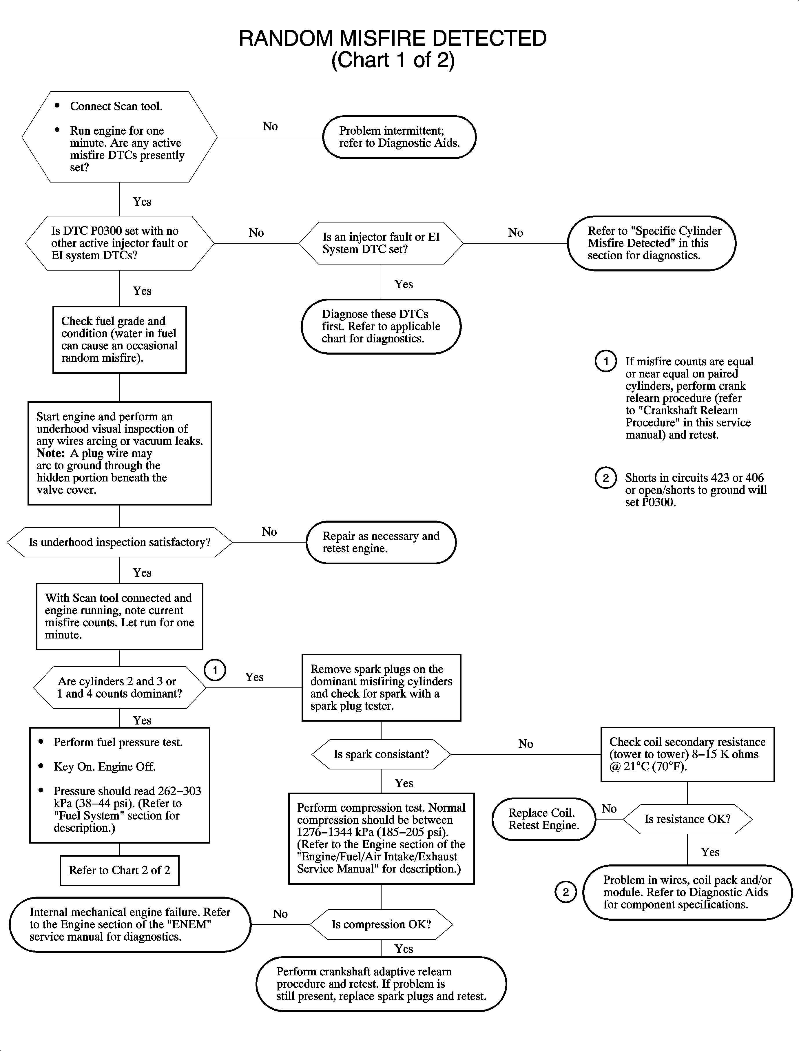
If an injector, EST, or EGR DTC is active and a misfire is active, diagnose
those DTCs first.
Use the scan tool to monitor active misfire counts. Spraying water on the wires
provides a good path for current to flow to ground on a bad wire. The scan tool active
misfire counts should pick up an intermittent misfire problem. Watch the scan tool
misfire counter. When a specific cylinder misfires under certain load, conditions
may be duplicated in the stall.
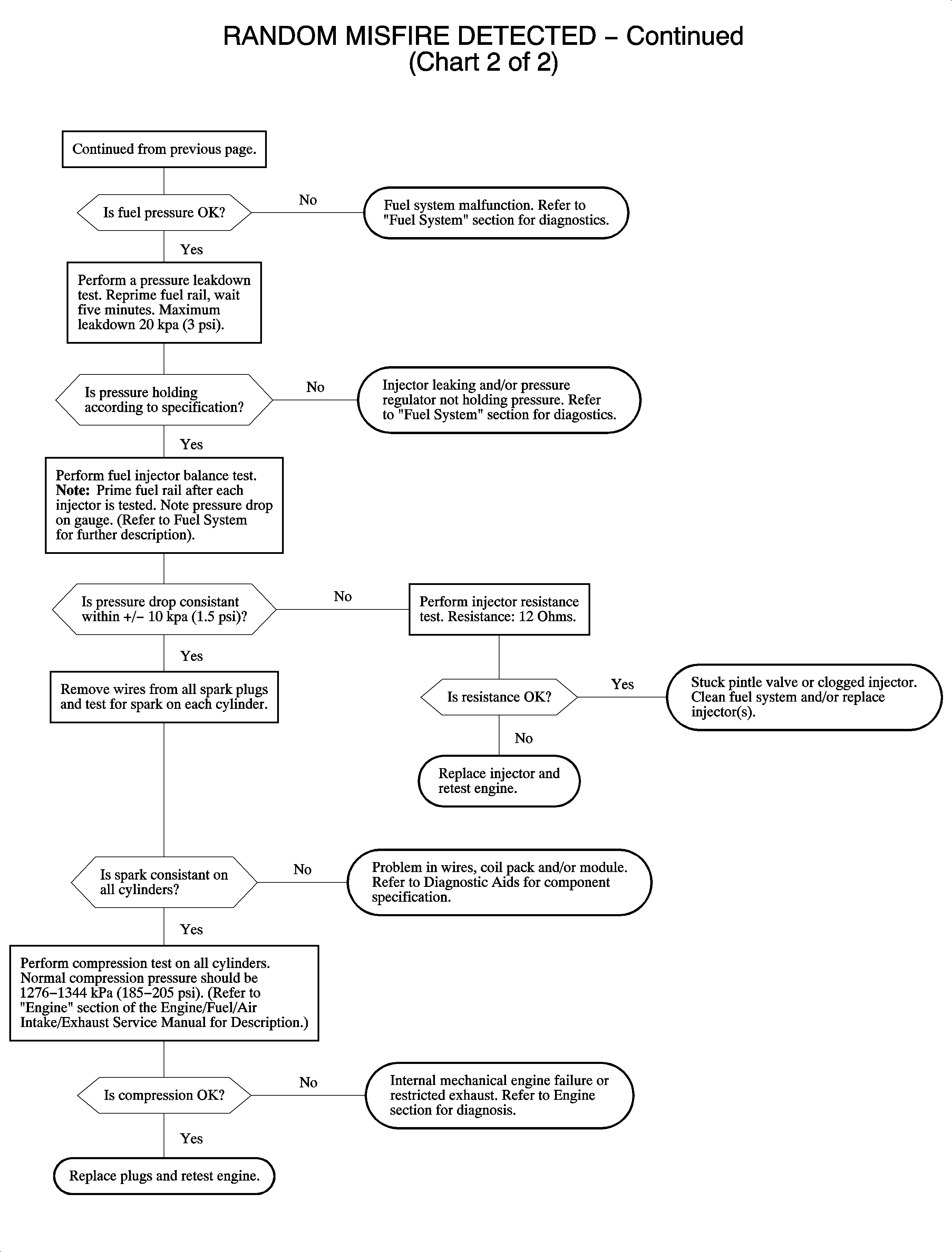
| • | Injector resistance is 12 ohms. |
| • | Wire resistance is under 12k ohms. |
| • | Spark plug gap is 0.04 in. |
| • | Coil pack secondary resistance, tower to tower, is 8-15k ohms. |
| • | Wire positioning on the coils is 4-1-2-3. |


