| Subject: | Harsh Shifts, Erratic Shifts, Lack of Power, Creep Forward in Neutral, No
Gears, or Gear Stuck On and Multiple Diagnostic Trouble Codes (DTCs) Set (Replace
Control Valve Body Assembly, Recondition Transaxle, and Flush Transaxle Oil Cooler
and Lines) |
| Models: | 1999 Saturn S-Series vehicle equipped with MP6/MP7 automatic transaxles built
between and including VIN XZ293158 - XZ33103 |
Condition
Some customers may comment of harsh shifts, erratic shifts, no gears, or a gear
stuck on with Service Engine Soon telltale illuminated and multiple diagnostic trouble
codes (DTCs may included any of the following: P0731, P0732 through P0741, and/or
P0782, P0783.)
Some owners may also comment of lack of power, vehicle will not accelerate,
or vehicle may surge while driving. All these symptoms could be intermittent initially,
but later develop into a clutch failure.
Cause
Iron sediment that settles in the control valve body assembly can cause control
valves to seize or have limited travel during operation. A control valve that is seized
or has limited travel can allow fluid pressure to be inadvertently directed to a clutch
that is not being commanded to apply by the powertrain control module (PCM).
Correction
Replace control valve body assembly, recondition damaged components, and flush
transaxle oil cooler and lines.
Procedure:
Preliminary Diagnosis
Important: The slip monitor values must be recorded prior to disconnecting vehicle battery.
- Using a Scan tool, record all DTCs and transaxle slip monitor values.
| • | If DTCs are present, refer to the Transaxle Controls section of the 98-99
Automatic Transaxle Service Manual for the appropriate diagnostics for any DTCs set. |
| • | If DTCs are present continue to step 2. |
- Drive vehicle to verify condition.
- Remove transaxle control valve body assembly. (Refer to "Valvebody"
removal procedure in the In-Vehicle Service section of the 98-99 Automatic
Transaxle Service Manual.)
- Inspect control valve body and transaxle for the following conditions
and reconciliation transaxle if any are found.
| • | Automatic transaxle fluid (ATF) smells burnt or is any color other than
brilliant red. If transaxle has experienced excessive fluid temperatures, the ATF
will begin to break down. During this process the fluid will actually lose its red
color and will turn brownish in appearance and eventually will become will become
clear or transparent. |
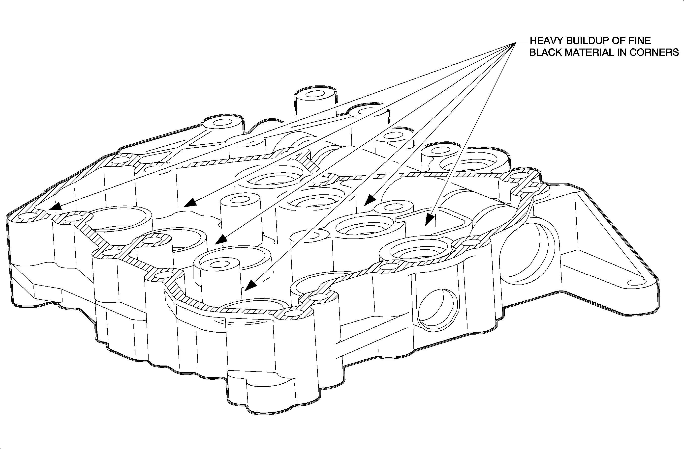
| • | Heavy amounts of iron sediment/debris present in or around valve body
casting, control valve solenoids, filter magnet, and/or clutch housing. On vehicle
with fewer than 2000 miles (3200 kilometers), only slight traces of iron sediment
in these areas can be considered normal. Heavy or thick build up of iron sediment
indicates transaxle clutch and control valve body damage. (Refer to illustration below.) |

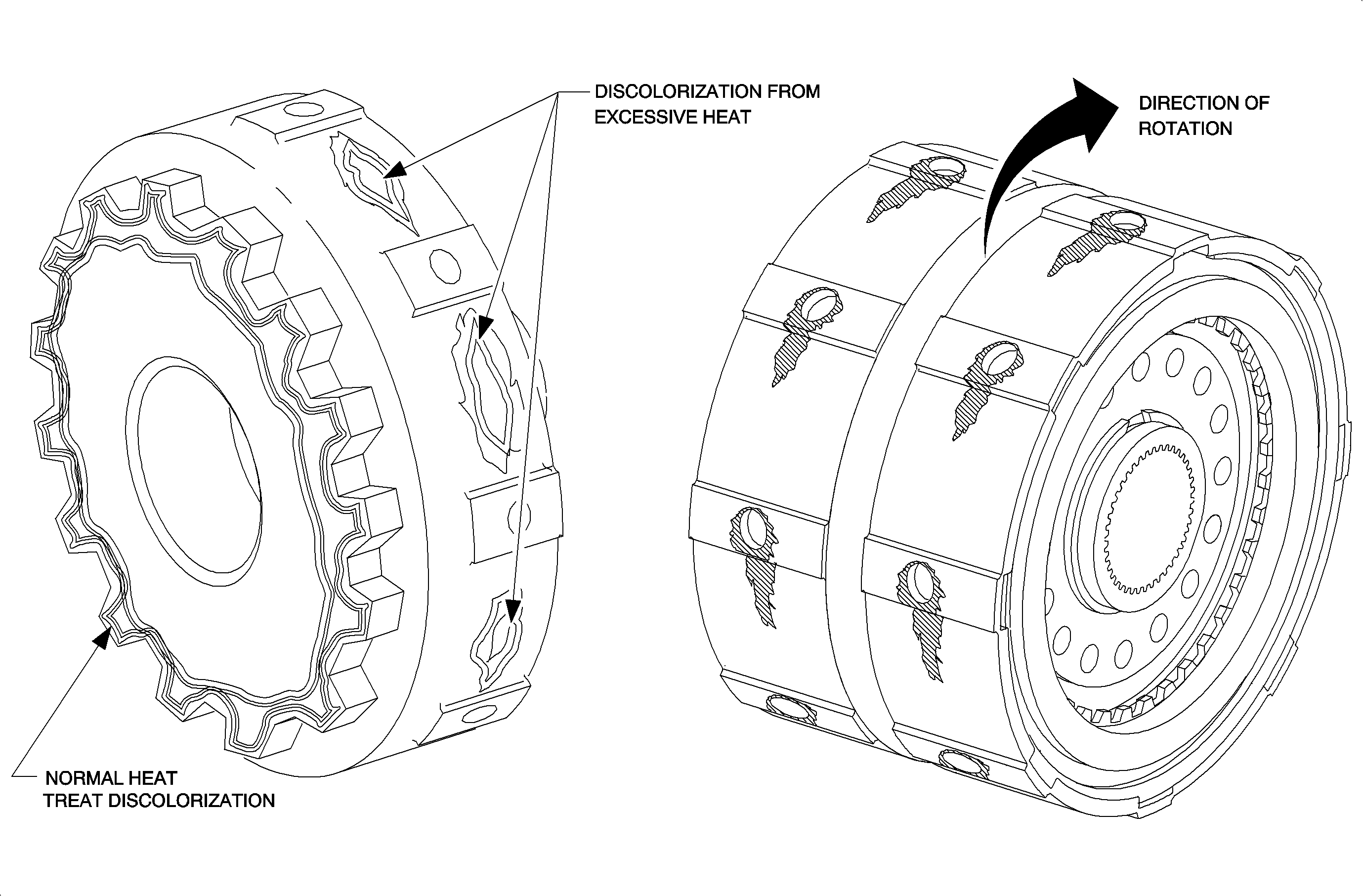
| | Important: The 4th clutch housing has a normal heat treat discoloration in the area where
the Park gear applies.
|
| • | Clutch housing lube holes have clutch residue or clutch housings show
discoloration due to excessive heat. (Refer to illustration below.) |

Transaxle Recondition / Inspection
- Remove transaxle from vehicle. (Refer to "Automatic Transaxle Removal"
procedure in the Out-of-Vehicle Service section of the 98-99 Automatic
Transaxle Service Manual.)
- Continue to follow the procedures in the Out-of-Vehicle Service
section of the 98-99 Automatic Transaxle Service Manual to recondition transaxle
assembly.
Caution: PROTECT YOURSELF BY WEARING SAFETY GLASSES WHEN PERFORMING THE FOLLOWING CLEANING
PROCEDURES.
- Perform the following cleaning procedures:
| • | While end cover assembly is dissembled, thoroughly flush end cover passages
and feed tube using a recommended brake cleaner or carburetor cleaner. Use compressed
air to ensure all debris is cleared and passages are dry. |
| • | Using the Oil Cooler Liner Flusher SA9165T, or equivalent, flush transaxle
oil cooler and lines using instructions included with tool. |
| - | If Oil Cooler Line Flusher SA9165T, is not available, flush transaxle
oil cooler and lines using a suction gun and a piece of 6 mm (1/4) rubber fuel line,
or equivalent. |
| - | Disconnect upper and lower cooler lines from transaxle. |
| - | Route upper cooler line to an approve oil drain container. |
| - | Attach a 6 mm (1/4 in.) rubber fuel line, or equivalent, to lower coolant
line. |
| - | Use a suction gun to draw up clean ATF or mineral spirits. |
| - | Slowly push ATF or mineral spirits through lower cooler line using suction
gun. |
| - | Periodically view upper cooler line that is routed to oil container until
ATF or mineral spirits being passed is clean and clear of contaminates. |
| - | Once clean and clear fluid begins to pass from upper cooler line, repeat
this procedure to back flush transaxle oil cooler and lines in the other direction
to ensure transaxle oil cooler and lines are clear of all contaminates. |
- Perform the following inspection procedures:
| • | Closely inspect all drive and driven gears for signs of heat distress
or wear on gear tooth contact areas. If heat stress or wear is evident on gears, replace
gear set(s). |
| • | Closely inspect torque converter hub that mates with transaxle oil pump. |
| - | If there are any signs of excessive heat distress or wear on torque converter
hub, replace torque converter and transaxle oil pump assembly. |
| - | If no signs of heat distress or wear are evident, drain and reuse during
transaxle assembly. |
- Obtain control valve body assembly (P/N 21002897) and replace during transaxle
assembly.
- Follow procedures in the Out-of-Vehicle Service section in the 98-99
Automatic Transaxle Service Manual to assemble transaxle.
- Install transaxle in vehicle. (Refer to "Automatic Transaxle Installation"
procedure in the Out-of-Vehicle Service section of the 98-99 Automatic
Transaxle Service Manual.)
- Using a Scan tool, reset transaxle adaptives and perform learn-in procedure.
(Refer to "Resetting Adaptive Parameters" and "Learn-In Procedure"
in the Diagnostic Information section of the 98-99 Automatic Transaxle Service Manual.)
- Test drive vehicle to verify proper repair.
Parts Requirements
21002897 - Control Valvebody Asm
Claim Information
To receive credit for this repair during the warranty coverage period, submit
a claim through the Saturn Dealer System for K7163 (Shaft and/or Components, Second/Reverse
and Third Drive Clutch Housing Assembly Input - Replace) or K7145 (Shaft and/or
Components, Fourth Clutch and Park Housing Assembly Output - Replace). Or,
if another procedure is performed, refer to the appropriate Electronic another procedure
is performed, refer to the appropriate Electronic Labor Time Guide for the correct
Labor Operation Code and Time.


