Tools Required
SA9303BR Stop Lamp Switch
Adjustment Gage
Adjustment Procedure
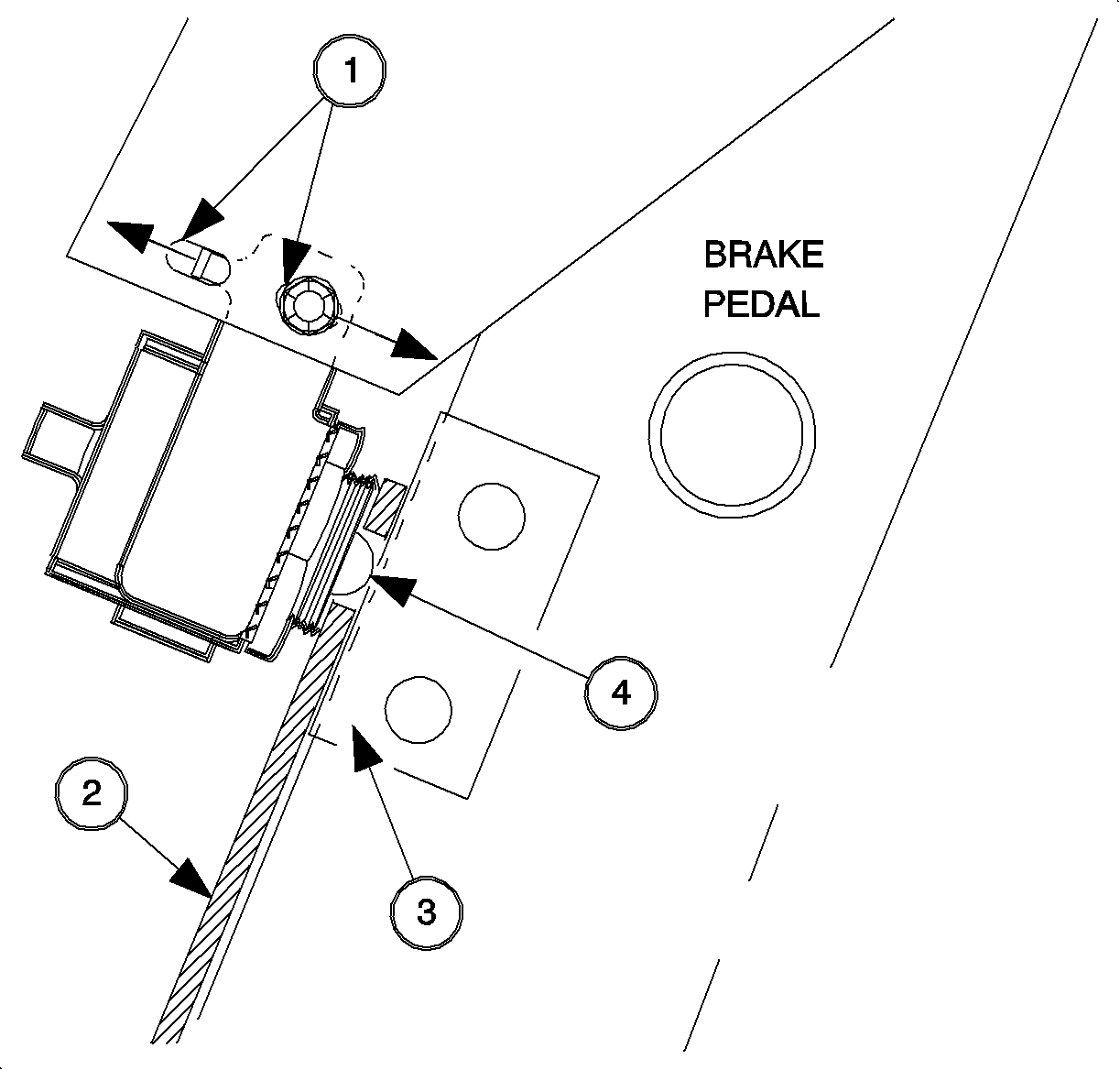
- Loosen the stop lamp switch mounting nut sufficiently to allow the switch to
move forward and rearward in the adjustment slot (1).
- Install SA9303BR
(2)
between the switch and the switch actuator pad (3) on the brake pedal arm being
sure that the plunger (4) protrudes through the slot in the gage.
- While pulling up with moderate force on the brake pedal assembly, push
the switch forward against the gage.
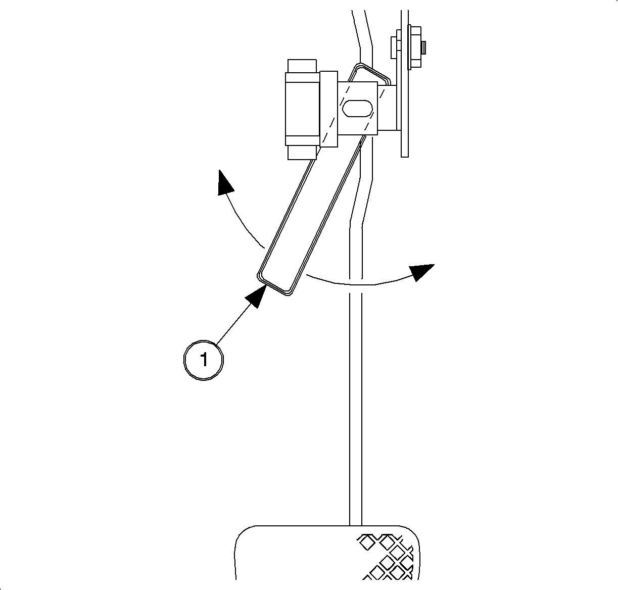
Important: Hold the switch perpendicular to the actuator pad on the brake pedal arm to
prevent the switch from rotating out of alignment when tightening the mounting nut.
- Tighten the switch mounting nut.
Tighten
Tighten nut to 10 N·m (89 lb in).
- Release the brake pedal assembly.
- With the pedal released and the adjustment gage (1) still in position,
tap the gage side-to-side:
| • | If the gage swings freely side-to-side, proceed to step 7. |
| • | If the gage sticks or does not swing freely, repeat steps 1 through
6. |
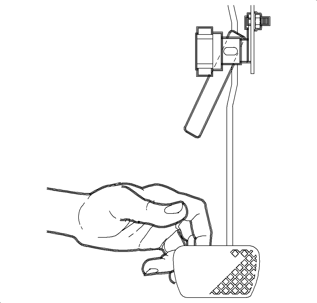
- With the adjustment gage in position, pull up on the brake pedal with
very light force, approximately 9 N (2 lb) and tap the gage side-to-side:
| • | If the gage swings freely, repeat steps 1 through 7. |
| • | If the gage sticks and/or does not swing freely, proceed to step 8. |
- Inspect switch plunger:
| • | If 0.8-1.2 mm (0.03-0.05 in) of the plunger
is visible between the switch and the switch actuator pad on the brake pedal arm,
the switch is correctly adjusted. The height of the rounded crown of the plunger
is equivalent to 1 mm (0.04 in). |
| • | If more than 1.2 mm (0.05 in) or less than 0.8 mm
(0.3 in) of the plunger is visible, repeat steps 1 through 8. |
Inspection Procedure
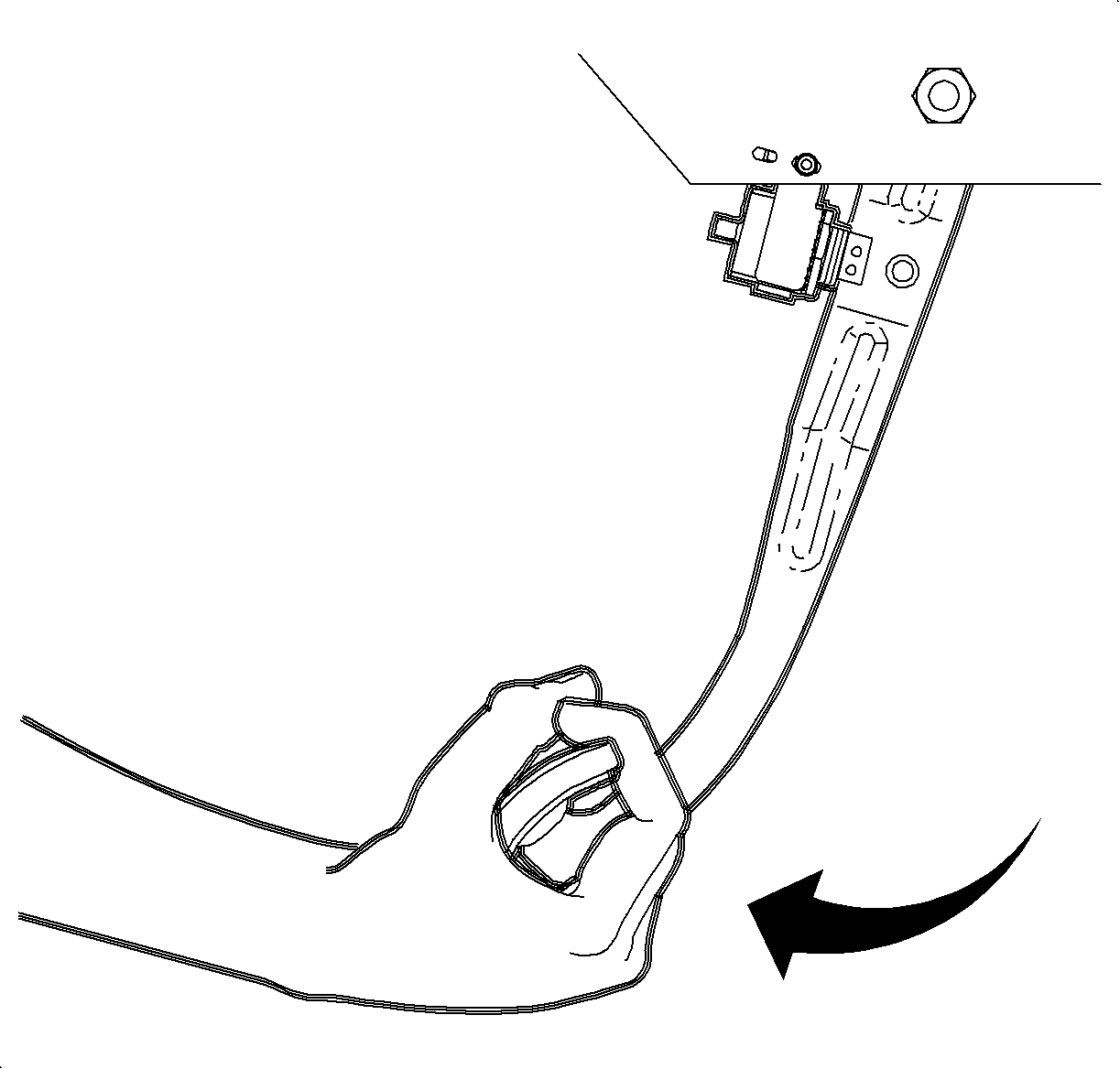
- View the stop lamp switch and the mounting bracket while pulling up on the
brake pedal assembly with moderate force, approximately 89 N·m (20 lb ft).
- If the switch and/or bracket movement is noticed, refer to Adjustment
Procedure.
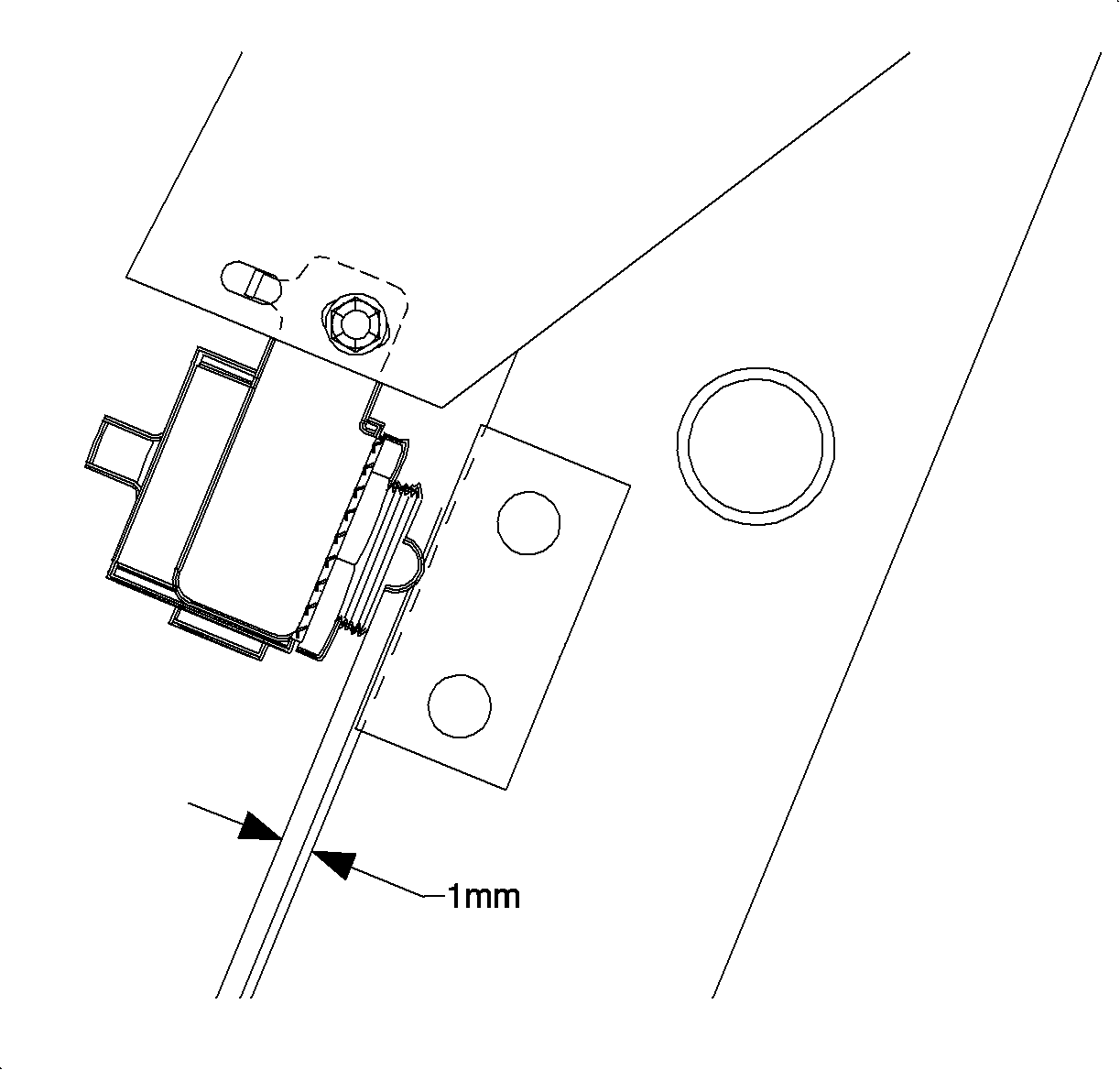
- If no movement is noticed, release the pedal assembly and inspect the switch
plunger. The plunger is green in color and located in the center of the switch:
| • | If 0.8-1.2 mm (0.03-0.05 in) of the plunger
is visible between the switch and the switch actuator pad on the brake pedal arm,
the switch is correctly adjusted. The height of the rounded crown of the plunger
is equivalent to 1 mm (0.040 in). |
| • | If more than 1.2 mm (0.05 in) or less than 0.8 mm
(0.03 in) of the plunger is visible, perform the Stop Lamp Switch Adjustment. |


