Objectionable Engine Vibration at Idle

| Subject: | Objectionable Engine Vibration at Idle (Check Engine Mount, Cooling Module Mounts, Engine Strut Cradle Bracket, Muffler Hanger and Strap, A/C Suction Hose, and Adjust or Replace as Required) |
| Models: |
| 1991 - 2002 All Saturn S-Series vehicles |
| Due to addition of 1997-2002 model years to Models Affected and new Parts Requirement, this bulletin supercedes bulletin 95-T-36, which should be discarded. |
Condition
Some customers may comment about objectionable engine vibration at idle. This condition may be more noticeable when the engine reaches normal operating temperature.
Cause
Objectionable engine vibration at idle may be caused by one or more of the following conditions:
| • | Engine not idling properly. |
| • | Worn engine mount assembly. |
| • | 1st design lower coolant module grommets. |
| • | Improperly positioned upper module grommets. |
| • | Preloaded engine strut cradle bracket. |
| • | Improperly positioned muffler hanger and strap. |
| • | Improperly positioned A/C suction hose. |
Correction
Refer to procedures to diagnose and repair any condition that could cause objectionable engine vibration at idle.
Some level of engine vibration is normal during initial engine warm-up. Engine idle vibration quality should be evaluated only when the engine reaches operating temperature and when the engine maintains a stable RPM. Before evaluating engine idle vibration quality, road test the vehicle and verify that the condition is present with the engine at operating temperature. Using a scan tool, make sure the engine's ignition and fuel systems are functioning properly. If the engine is not running properly, repair as needed.
Vibrations are normally felt in the steering wheel, lower seat cushion, seat back, or floor pan. Vibrations should be diagnosed with the vehicle stopped and the transaxle in Drive ("D") for automatic transaxles and in Neutral for manual transaxles.
CHECK ENGINE MOUNT MEASUREMENT
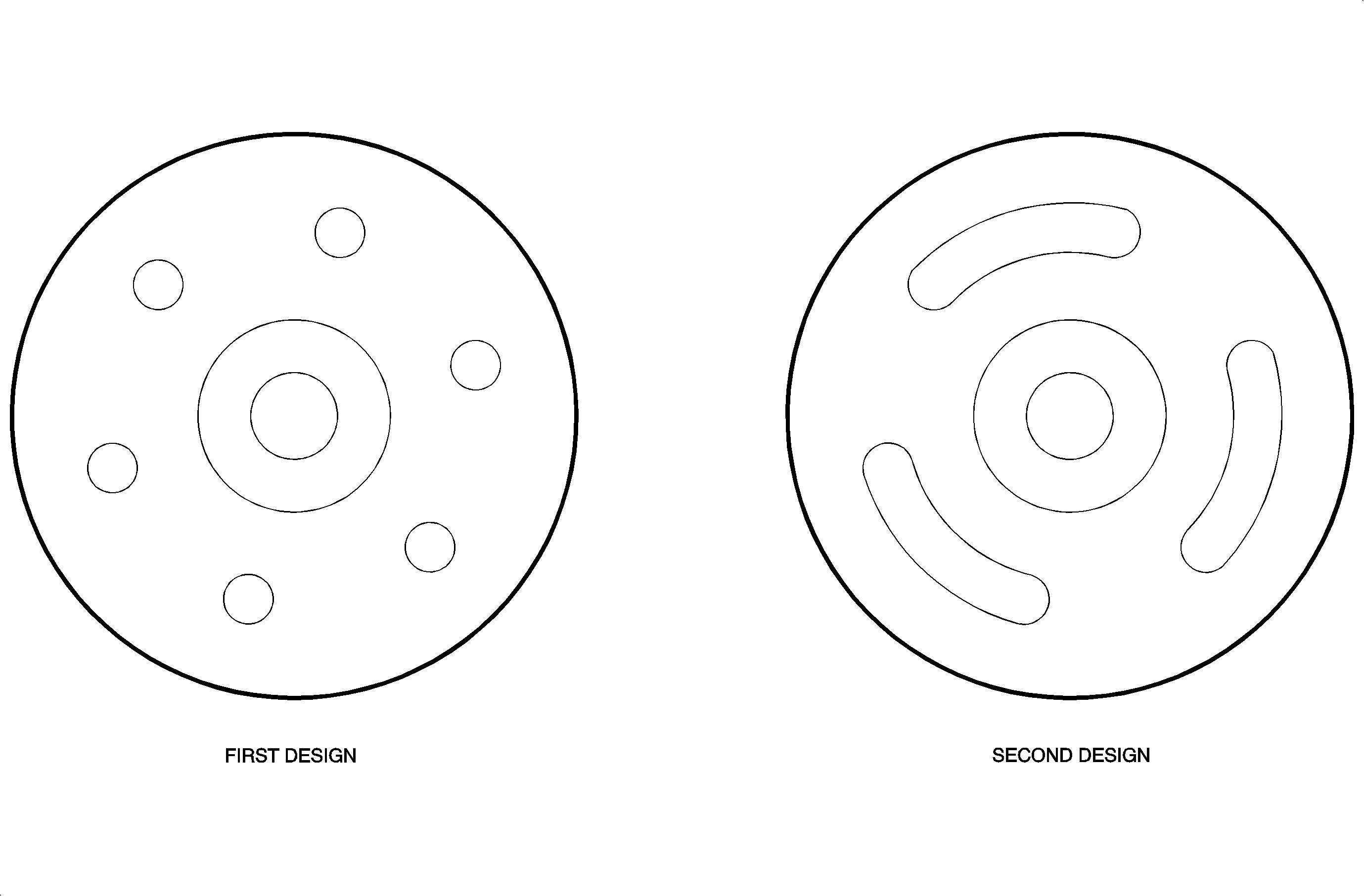
Inspect the vehicle to see if current top engine mount is a first or second design mount. Refer to the following illustrations to determine which procedure to follow.
Important: The First Design Engine Mount measurement procedure can be used to measure both first and second design engine mounts. The Second Design Engine Mount measurement procedure can only be used for the second design mounts.
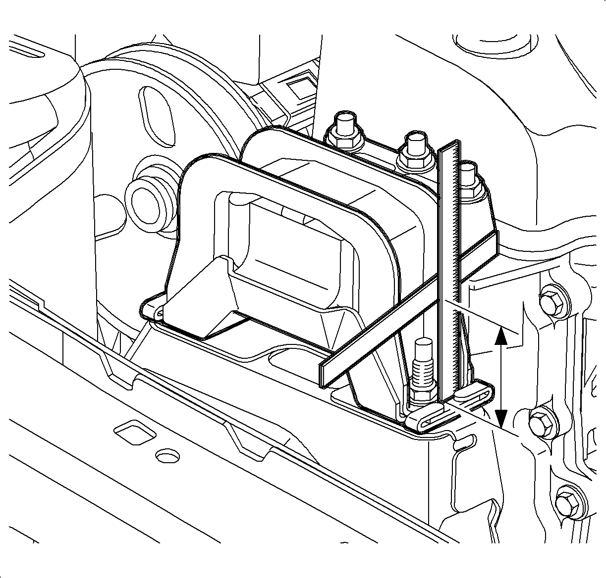
First Design Engine Mount
Using two 150 mm (6 in.) scales or a 150 mm (6 in.) scale and a suitable straight edge, measure engine mount assembly as shown in the First Design Mount illustration.
| • | If measurement is equal to or less than 39 mm (1 17/32 in.), replace engine mount assembly. Refer to applicable Chassis Service Manual. |
| • | If measurement is greater than 39 mm (1 17/32 in.), engine mount assembly does not require replacement. |
Second Design Engine Mount
Measure gap in mount at location shown in the Second Design Mount illustration. A 2 mm (5/64 in.) allen wrench or hex key can be used as a go/no go gauge for this measurement.
| • | If tool does not fit in gap, replace engine mount assembly. Refer to applicable Chassis Service Manual. |
| • | If tool fits in gap, engine mount assembly does not require replacement. |
CHECK COOLING SYSTEM GROMMETS
Check the lower cooling module grommets located in the pockets of the cradle. If the cooling module grommets are 1st design, P/N 21030708, replace with new 2nd design, P/N 21031313. The second generation cooling module mounts were introduced during the 2002 model year production.
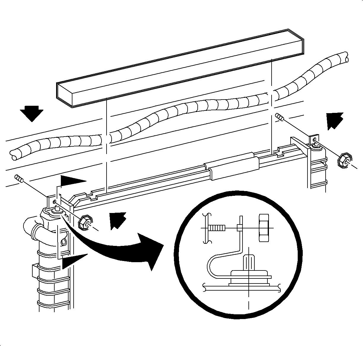
Check upper cooling module grommets for binding, misalignment, and freedom of movement. Cooling module retaining pins must be centered in grommets for support by upper radiator brackets, and cooling module should move from left to right, forward and rearward freely a minimum of 3.18 mm (1/8 in.). If grommets are pinched, loosen upper radiator bracket(s) and reposition them. Make sure locator tang in each upper radiator bracket is properly positioned in upper tie bar slot.
Check for Preloaded Engine Strut Cradle Bracket
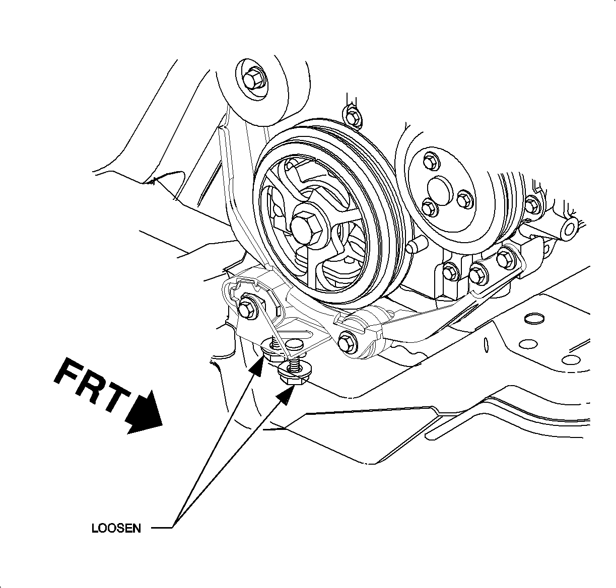
Check the powertrain for binding by pushing forward and rearward on the engine oil pan. The powertrain should travel a minimum of 3.18 mm (1/8 in.).
If the powertrain does not move, perform the following procedure:
- Check the engine and transaxle struts for correct installation and bushing wear.
- Loosen the engine strut bracket-to-cradle fasteners.
- Shake the powertrain by pushing forward and rearward on the engine oil pan.
- Allow the powertrain to settle to its natural position; tighten the two engine strut bracket-to-cradle fasteners.
Important: Make sure the engine strut bracket does not move forward or rearward when torquing the two fasteners.
Tighten
Tighten the engine strut bracket-to-cradle fasteners to 50 N·m
(37 lb-ft).
CHECK THE MUFFLER AND STRAP
- Check the entire exhaust system for alignment, clearance to heat shields, and leaks. The muffler body band clamp must be free to move in the hanger.
- Check that the muffler can be moved both vertically and horizontally in the muffler hanger. The muffler should move in the muffler hanger a minimum of 1.60 mm (1/16 in.) vertically (up/down) and 3 mm (1/8 in.) horizontally (side to side).
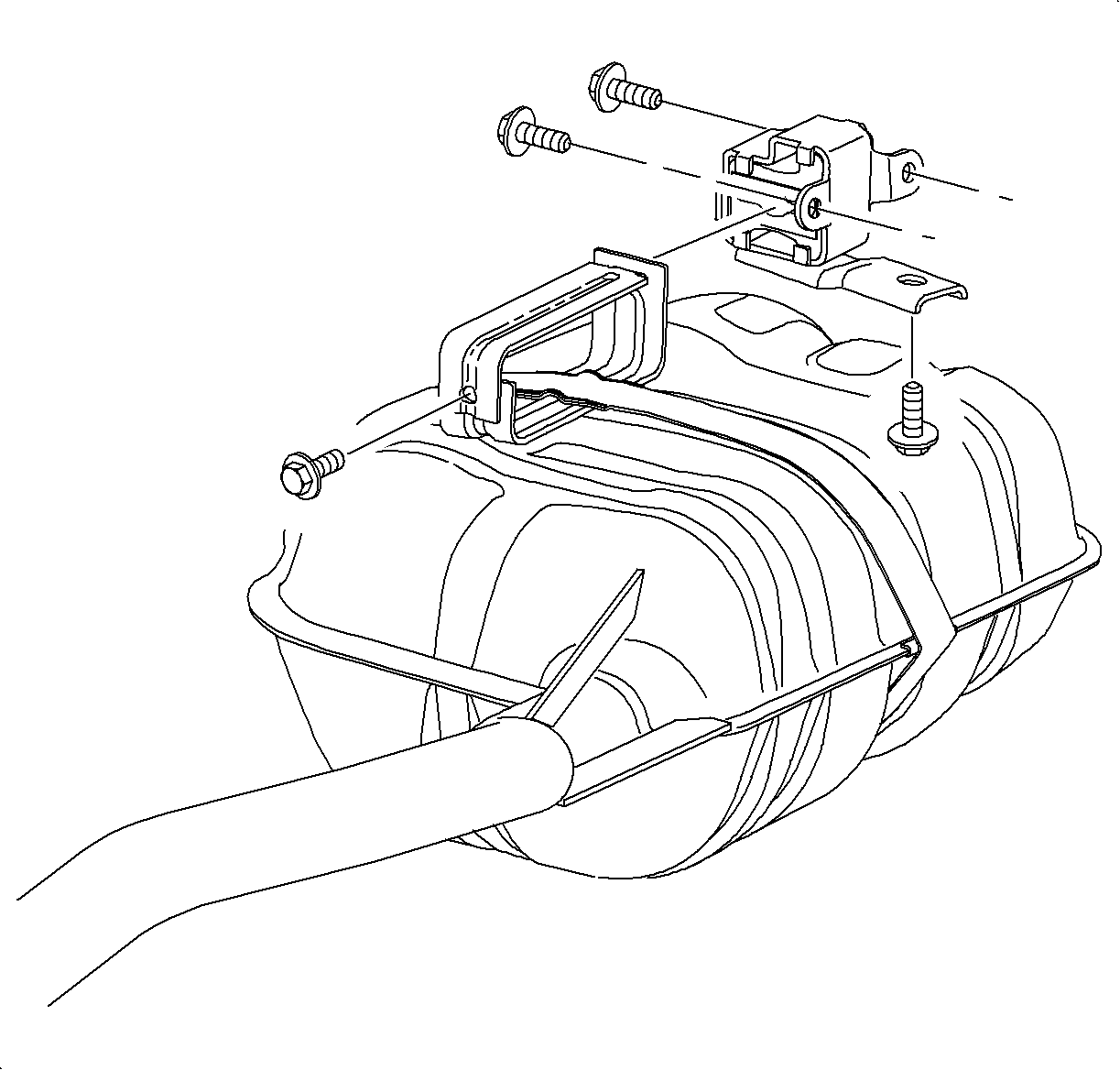
Important: If the specified muffler movement cannot be obtained, carefully lower the exhaust system and adjust the muffler hanger using washers or replace the muffler isolator block as needed. Washers with an inside diameter of 9.53 mm (3/8 in.) may have to be installed on the attachment bolt(s) between the muffler block bolt and the frame rail to align the muffler hanger parallel with the muffler.
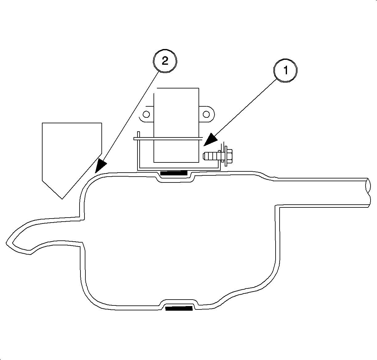
Important: Make sure the system has not shifted rearward allowing contact between the hanger bracket bolt and the hanger block (1). Ensure a 19 mm (3/4 in.) clearance between the muffler and the muffler ramp (2).
| • | If the muffler does not move freely, position the muffler to allow the movement described above. Refer to the "Exhaust" section of the Engine Service Manual of the appropriate model year vehicle. |
| • | If the muffler moves freely, exhaust system is correct. |
CHECK A/C SUCTION HOSE
If equipped with A/C, make sure A/C suction line does not contact transaxle.
Parts Information
Part Number | Description |
|---|---|
21031313* | MOUNT-RAD LWR |
(Supercedes P/N 21030708) | |
Claim Information
To receive credit for this repair during the warranty coverage period, submit a claim through the Saturn Dealer System using the appropriate Electronic Labor Time Guide for the correct Labor Operation Code and Time.
