Charging System Test for Saturn SL2/SC2 2002
Caution: Safety glasses should be worn and rings, watches, and all other hand jewelry should be removed.
- Verify the fusible link between the starter and generator is good.
- Verify the connections are tightened to specification and clean. The charging system light functional test will verify the link is OK.
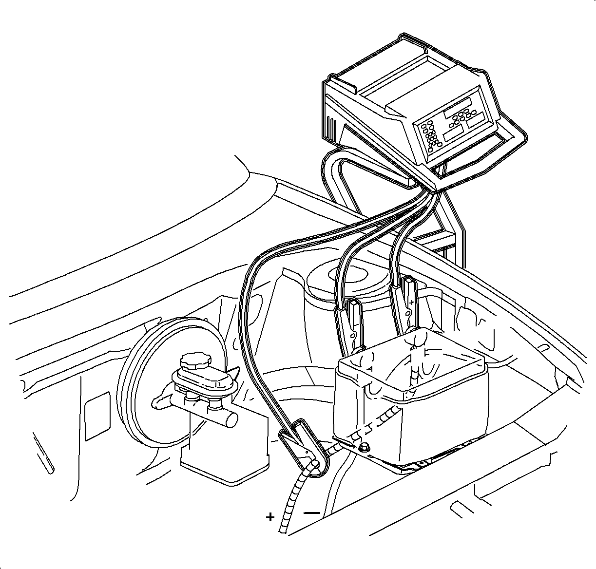
- Turn the system tester ON.
- Connect the large red tester cable to the battery positive (+).
- Connect the large black tester cable to the battery negative (-).
- Place the gray inductive current pick-up around the battery positive (+) cable. Make sure that the arrow on the gray inductive current pick-up is pointing toward the starter motor solenoid.
- Place the gray inductive current pick-up around the battery positive cable between the battery positive terminal and the starter motor solenoid connection. The easiest place to connect the inductive pick-up is next to the brake master cylinder. The battery positive cable runs under the master cylinder and is covered by a protective wire conduit. This conduit does not need to be removed for this test. On vehicles equipped with ABS brakes, the pick-up can be placed between the ABS master cylinder and starter motor.
- Perform the Battery Load Test to verify a good battery. Refer to Battery Load Test in Battery Inspection/Test .
- Start the vehicle and turn all accessories OFF.
- Follow the system tester prompts.
- Press CHARGING SYSTEM TEST. The display should show the correct number of cylinders. To change the number of cylinders, simply press that number on the keypad.
Important: If a fusible link is blown, do not just replace it. The most probable cause of a blown link is an internal generator failure. Verify that there is no external arcing or shorting of fusible link with other wires and/or components. If no problems are found, replace the generator.
Important: Verify the inductive current pickup is completely closed around the cable.
Notice: A flat battery will adversely affect the Charging System results. Perform a Battery Test before performing the Charging System Test.
Voltage: With a good battery in the vehicle, the voltage output should be between 13-15.5 V.
Current: Use the chart below to determine minimum output current.
Diode Pattern: Always ignore this test.
If the generator does not pass the above voltage and current tests and:
- Output current is below 20 A, verify the charge warning telltale operation on I/P cluster.
- Output current is above 20 A, but below the specified minimum current, verify the gray amp probe is properly installed and the belt is in good condition.
- If both pass, replace the generator.
Generator Output
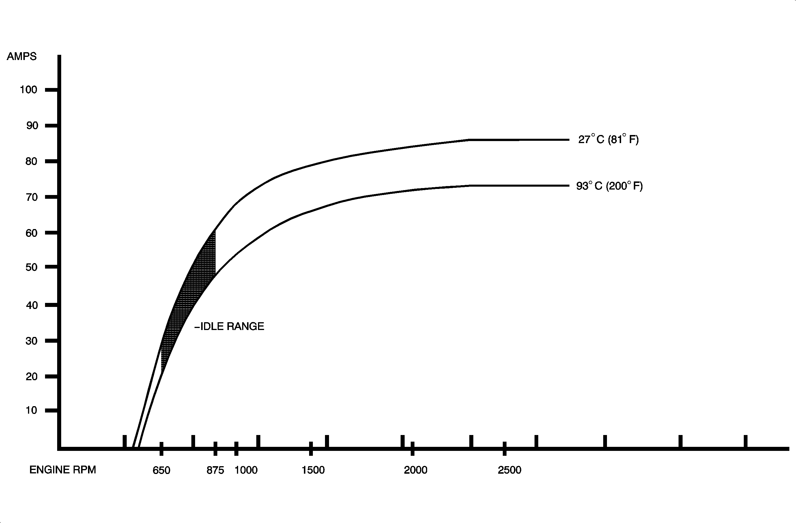
Important: When testing a generator, the load, temperature, and RPM must be considered to obtain the most accurate conclusion. When using the system tester or a carbon pile tester (carbon pile fully ON), the load will be approximately maximum load.
The output of the generator is dependant on the demand (load), vehicle temperature, and the RPM of the generator.
Load | If the vehicle electrical demand is low, all accessories are OFF, the output from the generator will be low. As the demand increases, accessories are ON, the generator output will increase. |
TEMPERATURE | As the temperature increases, the output from the generator decreases. |
RPM | The generator RPM is 2.57 times the engine RPM. As RPM increases, the output of the generator increases until it reaches maximum output, the generator fully loaded. At extended idle, low RPM, maximum load, and high temperatures the generator maximum output will be around 30 amps. |
Engine RPM | Approximate AMP Output | Generator Inlet Air Temp |
|---|---|---|
650 RPM 650 RPM | 28 amps 26 amps | 27°C (81°F) 93°C (200°F) |
875 RPM 875 RPM | 60 amps 48 amps | 27°C (81°F) 93°C (200°F) |
1000 RPM 1000 RPM | 67 amps 53 amps | 27°C (81°F) 93°C (200°F) |
1500 RPM 1500 RPM | 77 amps 64 amps | 27°C (81°F) 93°C (200°F) |
2000 RPM 2000 RPM | 85 amps 72 amps | 27°C (81°F) 93°C (200°F) |
Tolerance - 4 amps maximum | ||
