- Remove the air cleaner and duct assembly.
- Disconnect the negative battery cable from the battery.
- Remove the hold-down retaining nut and screws, and lift them off the battery hold-down retainer.
- Disconnect the powertrain control module (PCM) J2 (black 28-way) harness connector by moving the locking device toward the fender.
- Remove the PCM attachment bolts.
- Remove and flip the PCM on its side, out of the way.
- Remove the battery tray bolts and the tray.
- Back out the transaxle connector bolt and disconnect the transaxle connector.
- For antilock brake system (ABS) equipped vehicles, remove the master cylinder-to-booster nuts and the ABS mid-rail bracket bolt.
- Remove the valvebody cover.
- Remove the 11 valvebody-to-case bolts, identified on illustration by the heavy circles.
- Pull the valvebody up and disengage it from the manual valve link.
- Remove the valvebody.
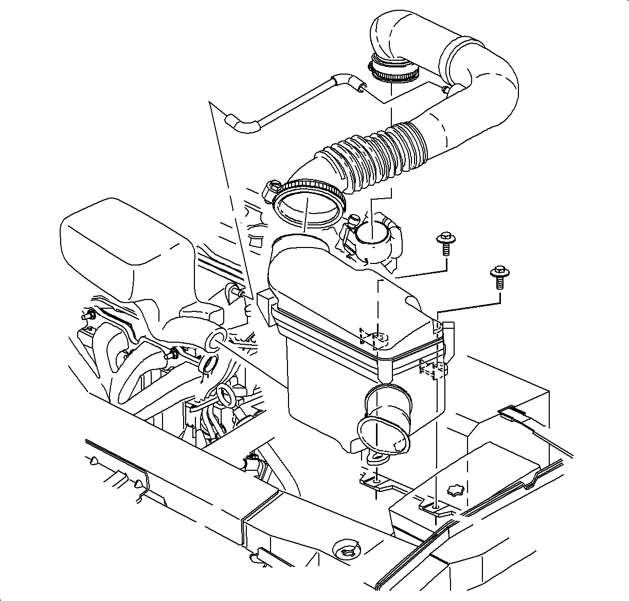
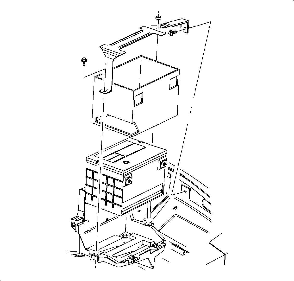
Caution: Unless directed otherwise, the ignition and start switch must be in the OFF or LOCK position, and all electrical loads must be OFF before servicing any electrical component. Disconnect the negative battery cable to prevent an electrical spark should a tool or equipment come in contact with an exposed electrical terminal. Failure to follow these precautions may result in personal injury and/or damage to the vehicle or its components.
Disconnect the positive battery cable from the battery.
Lift the battery out of the vehicle, and place the battery in a safe location.
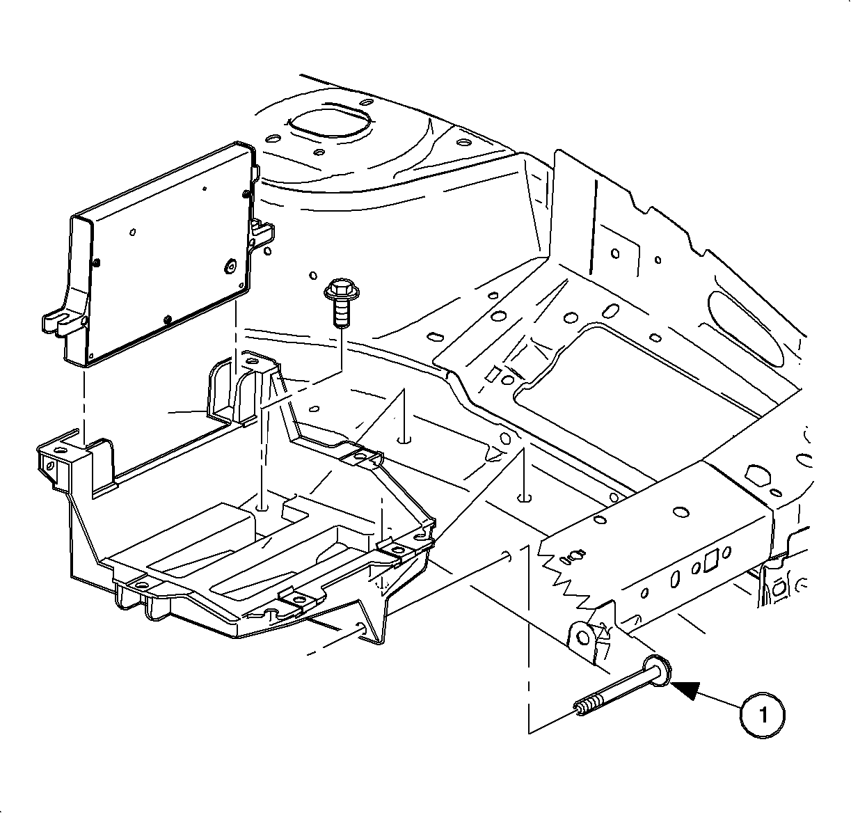
One bolt is located in the fender well.
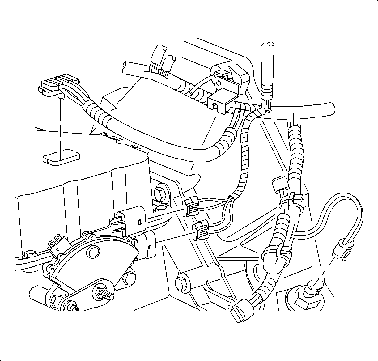
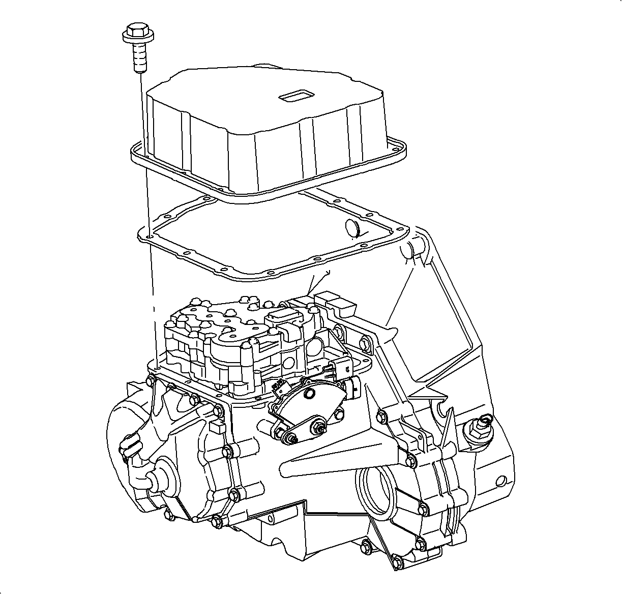
Notice: ABS equipped vehicles require the master cylinder to be moved off booster studs and the ABS mid-rail bracket bolt removed to allow the system to be lifted slightly for removal of the valvebody cover. Use care not to bend or kink brake lines. After removing the valvebody cover place the master cylinder back on the booster studs.
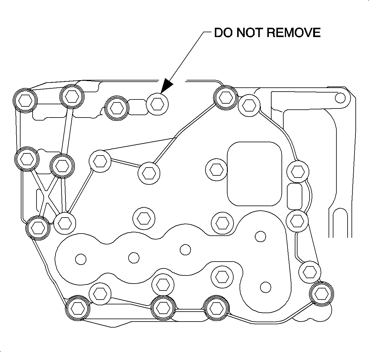
Notice: Do not remove the bolt indicated in the drawing. This bolt holds the upper and lower valvebody together as the valvebody is removed. If bolt is removed in the vehicle, parts will fall into the transaxle.
