- Lower the valve body into the case and insert the manual link into the manual valve.
- Install and finger tighten the valve body-to-case dowel bolts first. This procedure must be followed to ensure the valve body is properly aligned to the case. For reference, the bolts are identified as follows:
- Clean and lubricate the fasteners with Saturn Transaxle Fluid. Wipe off excess fluid and install.
- Tighten the valve body-to-case bolts using tightening sequence shown in the illustration.
- Verify the location of the valve body bolts
- Clean the transaxle case and the valve body cover sealing surfaces with Saturn Choke and Brake Cleaner or equivalent, applied with a clean shop towel.
- Align the valve body cover gasket on the valve body cover and install on the transaxle case.
- When installing the valve body cover, ensure to properly tighten the valve body cover bolts using the tightening sequence shown.
- Verify tightening of the valve body cover bolts to account for gasket relaxation using the tightening sequence shown.
- Install and tighten the master cylinder-to-booster nuts.
- Install and tighten the ABS mid-rail bracket bolt.
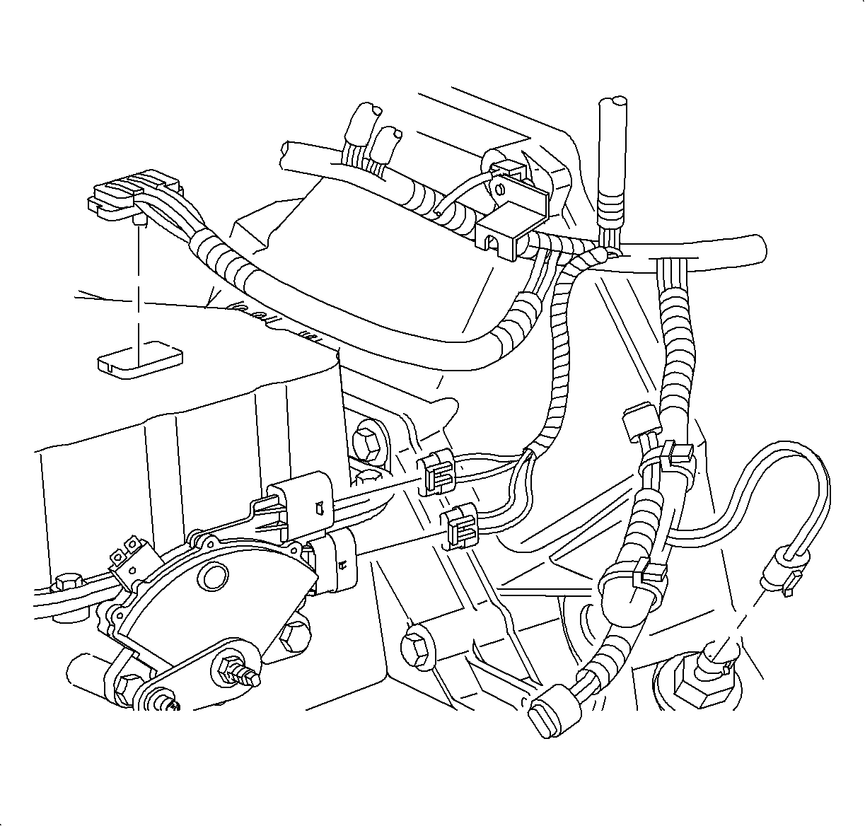
- Connect the transaxle solenoid harness connector.
- Install the transaxle connector bolt.
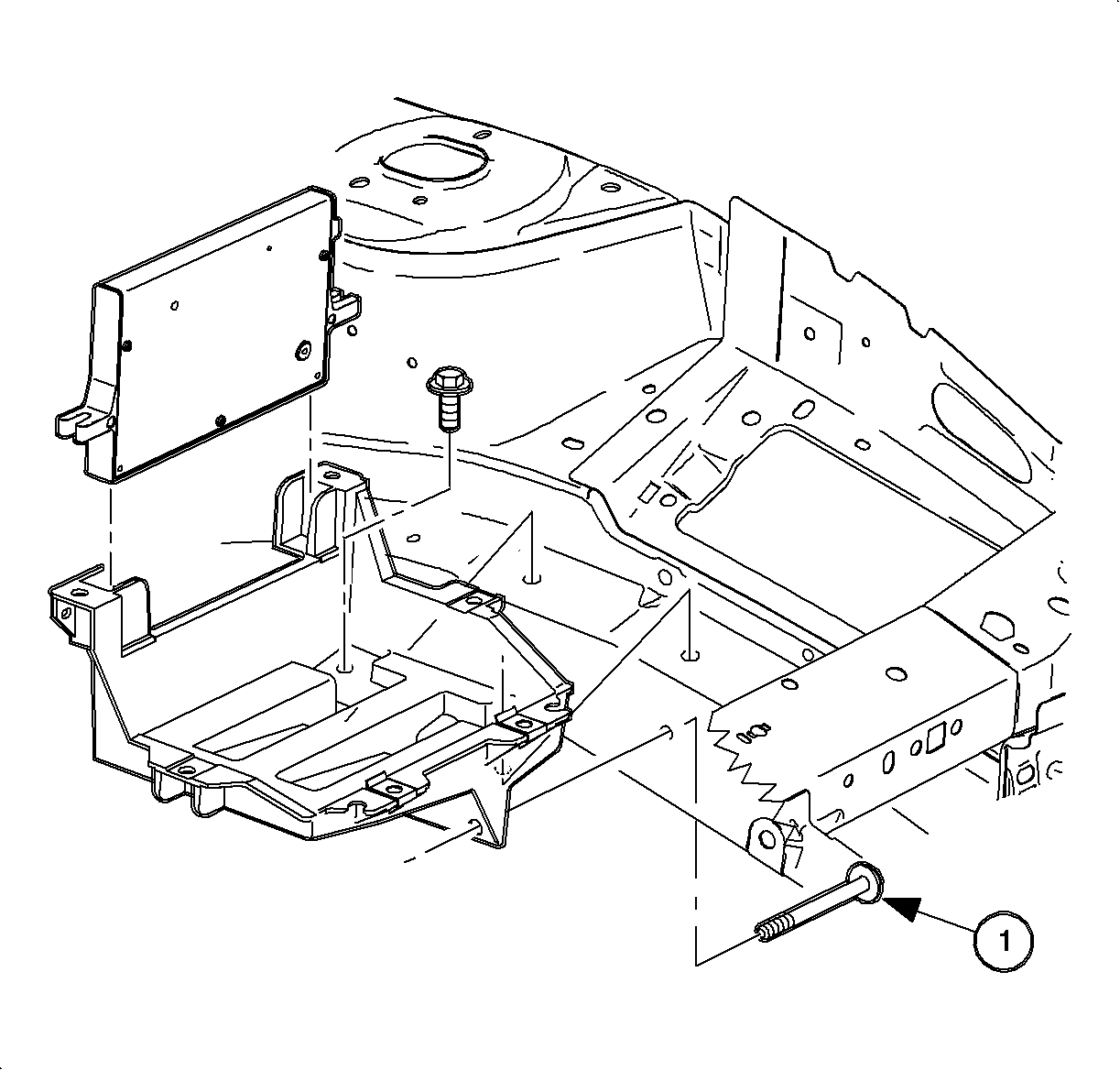
- Install the battery tray.
- Install the battery tray bolts.
- One bolt is located in the fender well.
- Install the powertrain control module (PCM) and attachment bolts.
- Connect the PCM J2 black 28-way connector and engage the locking device.
- Ensure the battery tray is clean.
- Ensure the battery cable ends are clean and free of corrosion. Clean with a wire brush.
- Ensure the battery is in good physical condition (e.g., no cracks, or obvious damage) and the terminals are clean.
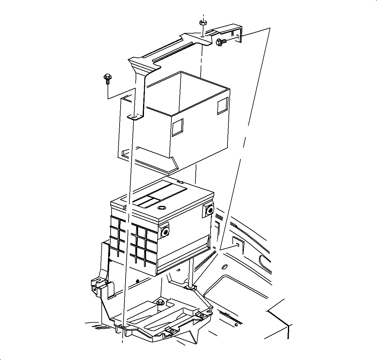
- Install the battery carefully in the battery tray; ensure the terminals do not short against any metal during installation.
- Install the battery hold-down retainer, locking the battery into the tray. Install and tighten the hold-down retainer nut and screws.
- Install the positive battery cable first.
- Install the negative battery cable last.
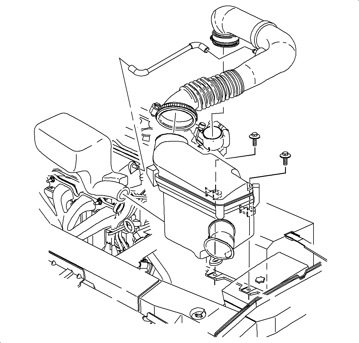
- Install the air cleaner and duct assembly.
- Set the clock.
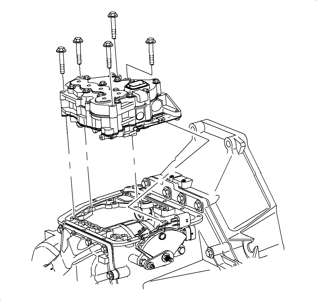
Important: The valve body-to-case bolts must be placed in the valve body prior to installation.
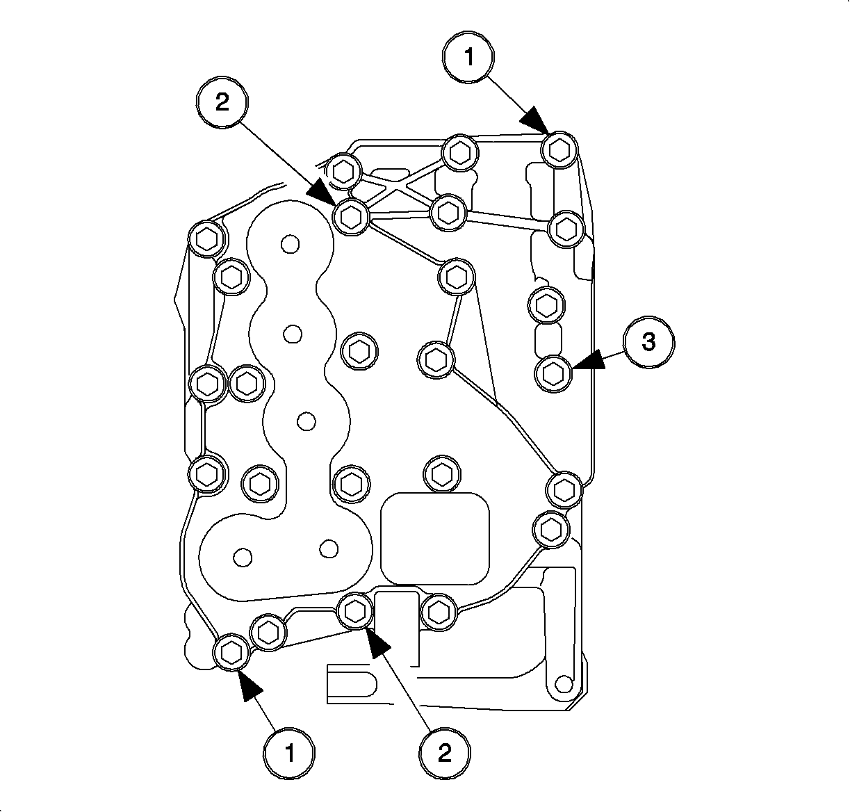
| • | The valvebody-to-case dowel bolts |
| • | The upper-to-lower valvebody dowel bolts |
| • | The bolt holding upper and lower valve body |
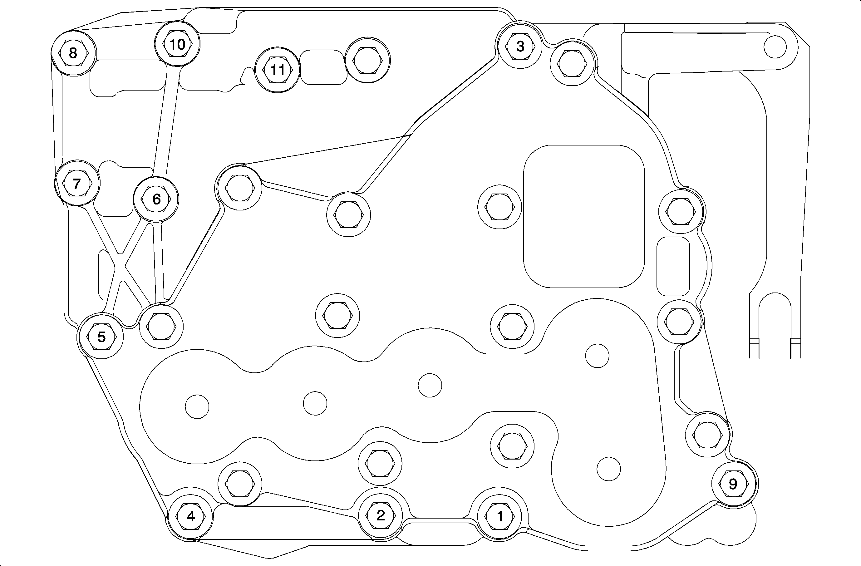
Notice: Use the correct fastener in the correct location. Replacement fasteners must be the correct part number for that application. Fasteners requiring replacement or fasteners requiring the use of thread locking compound or sealant are identified in the service procedure. Do not use paints, lubricants, or corrosion inhibitors on fasteners or fastener joint surfaces unless specified. These coatings affect fastener torque and joint clamping force and may damage the fastener. Use the correct tightening sequence and specifications when installing fasteners in order to avoid damage to parts and systems.
Notice: Over-torqueing bolts can cause valves to bind.
Tighten
Tighten the valve body assembly bolts to 11 N·m (8 lb ft).
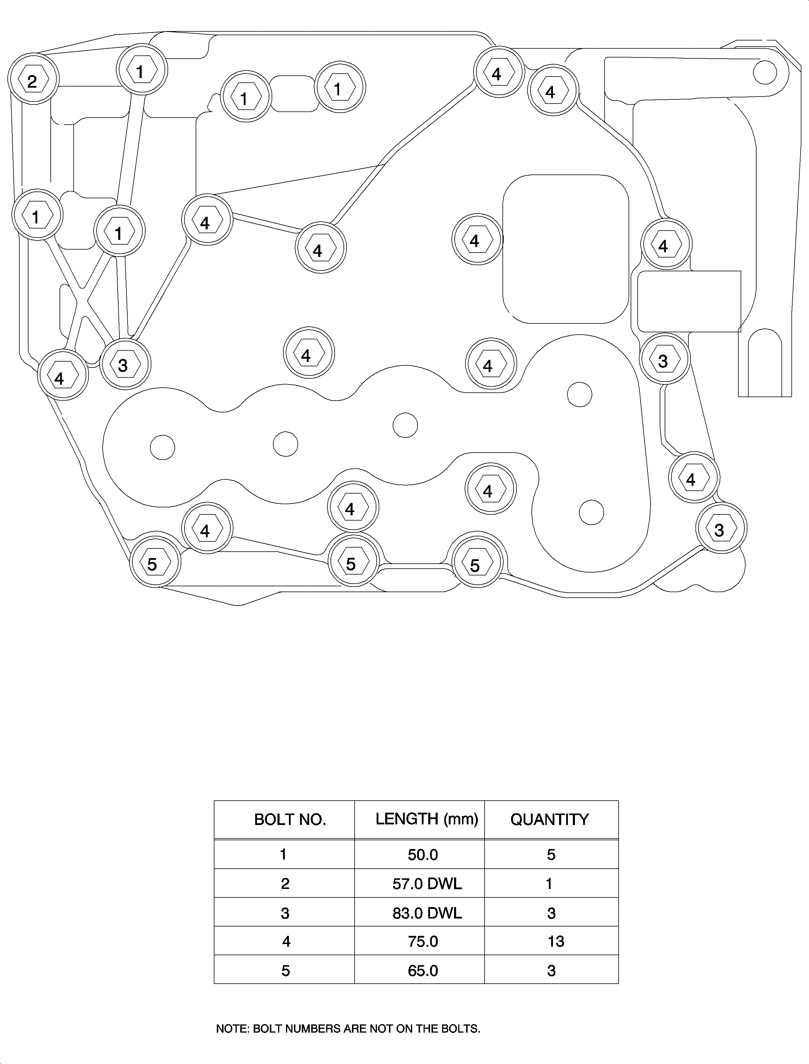
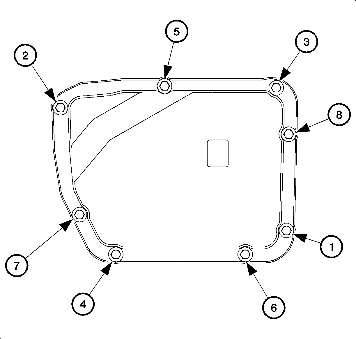
Important: Install the new gasket during reassembly.
Important: Clean and lubricate the fasteners with Saturn Transaxle Fluid. Wipe off excess fluid.
Tighten
Tighten the valvebody cover-to-case bolts to 12 N·m (9 lb ft).
Tighten
Tighten the valve body cover-to-case bolts to 12 N·m (9 lb ft).
Tighten
Tighten the brake master cylinder-to-booster nuts to 27 N·m (20 lb ft).
Tighten
Tighten the anti-lock brake system (ABS) bracket-to-midrail bolt to 16 N·m
(9 lb ft).
Notice: Do not over-tighten or damage to the connector plate may occur.
Tighten
Tighten the transaxle electrical connector bolt to 3 N·m (27 lb in).
Tighten
Tighten the battery tray-to-frame rail bolts to 10 N·m (89 lb in).
Tighten
Tighten the PCM-to-battery tray bolts to 6 N·m (53 lb in).
Tighten
Tighten the battery case bracket stud and nut to 9 N·m (80 lb in).
Tighten
Tighten the battery terminal bolts to 17 N·m (13 lb ft).
Tighten
Tighten the battery terminal bolts to 17 N·m (13 lb ft).
