Service Manual Update for Inner Tie Rod Removal and Installation Procedures that were Ommitted from the Steering Section of the Chassis Service Manual

| Subject: | Service Manual Update for "Inner Tie Rod" Removal and Installation Procedures that Were Omitted from the Steering Section of Chassis Service Manuals |
| Models: | 1997 - 1999 Saturn vehicles |
Purpose
The purpose of this bulletin is to provide service procedures for the inner tie rods that were omitted from the 1997, 1998, and 98-99 combined Chassis service manuals.
The following pages provide the inner tie rod removal and installation procedures. Copies of this bulletin should be made and inserted in the "Steering" section of all 1997, 1998, and 98-99 combined Chassis service manuals at Saturn retailers.
INNER TIE ROD
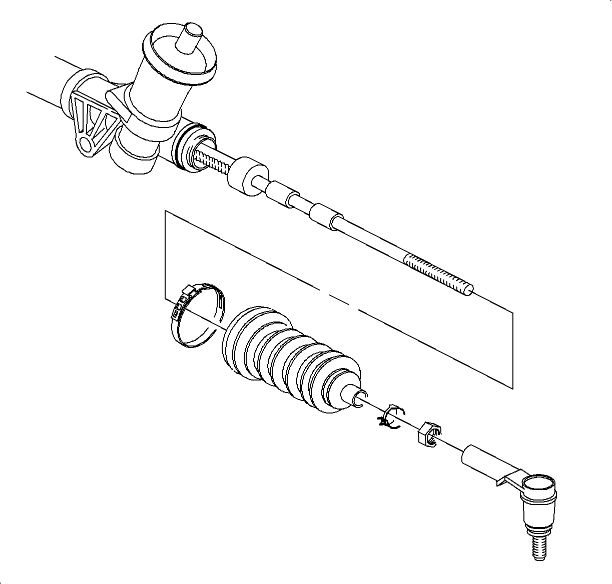
REMOVAL
Caution: MAKE SURE VEHICLE IS PROPERLY SUPPORTED AND SQUARELY POSITIONED ON HOIST. TO HELP AVOID PERSONAL INJURY, PROVIDE ADDITIONAL SUPPORT TOT HE OPPOSITE END OF THE VEHICLE THAT COMPONENTS WILL BE REMOVED FROM.
- Raise vehicle on hoist.
- Remove wheels.
- Loosen outer tie rod-to-inner tie rod lock nut.
- Remove steering gear, following the appropriate procedure (manual or power steering) outlined in the Steering section of the appropriate model year Chassis Service Manual.
- Unthread outer tie rod from inner tie rod.
- Remove outer tie rod lock nut.
- Remove steering gear boot.
- Remove shock damper off inner tie rod by sliding it toward the steering gear.
- Remove inner tie rod assembly from steering gear.

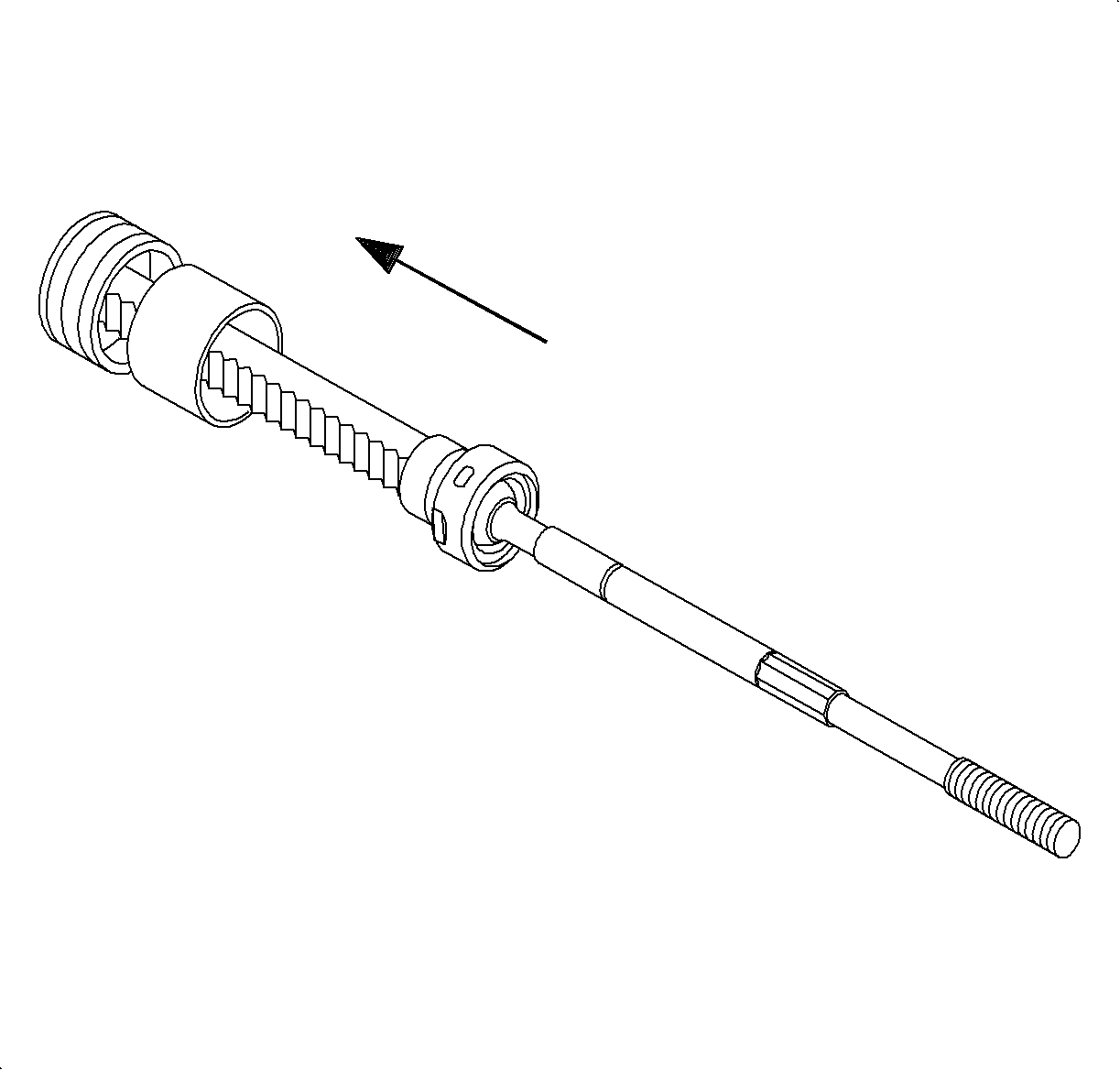
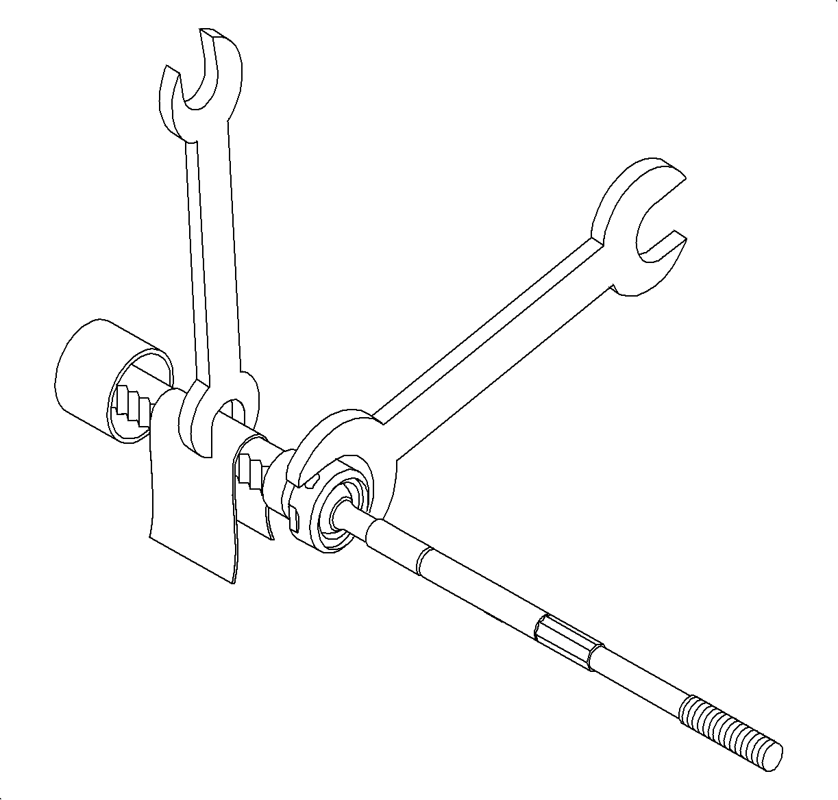
Notice: Steering gear rack must be held stationary during inner tie rod removal to prevent steering gear damage. Use an appropriate size wrench at the rack teeth to hold the rack during inner tie rod removal. Protect rack teeth with a shop cloth. For right side inner tie rod removal, it will be necessary to remove the left side boot to access the rack teeth.
Installation
- Remove old Loctite from threads of rack and inner tie rod.
- Apply Loctite 262 (or equivalent) to inner tie rod threads.
- If shocker damper was removed, slide it onto steering gear.
- Using Saturn tool SA-9209C, install inner tie rod assembly onto steering gear.
- Slide shock damper up against inner tie rod assembly.
- Install steering gear boot onto steering gear.
- thread inner tie rod-to-outer tie rod lock nut onto inner tie rod.
- Thread outer tie rod onto inner tie rod.
- Install steering gear into vehicle using the appropriate procedure (manual or power steering) previously listed.
- Position wheel onto hub.
- Install wheel nuts and tighten in a crisscross pattern to be sure torque is correct.
- Set toe. (Refer to "wheel Alignment" in the Alignment, Wheels & Tires section of the appropriate model year Chassis Service Manual.)
- Lower vehicle.
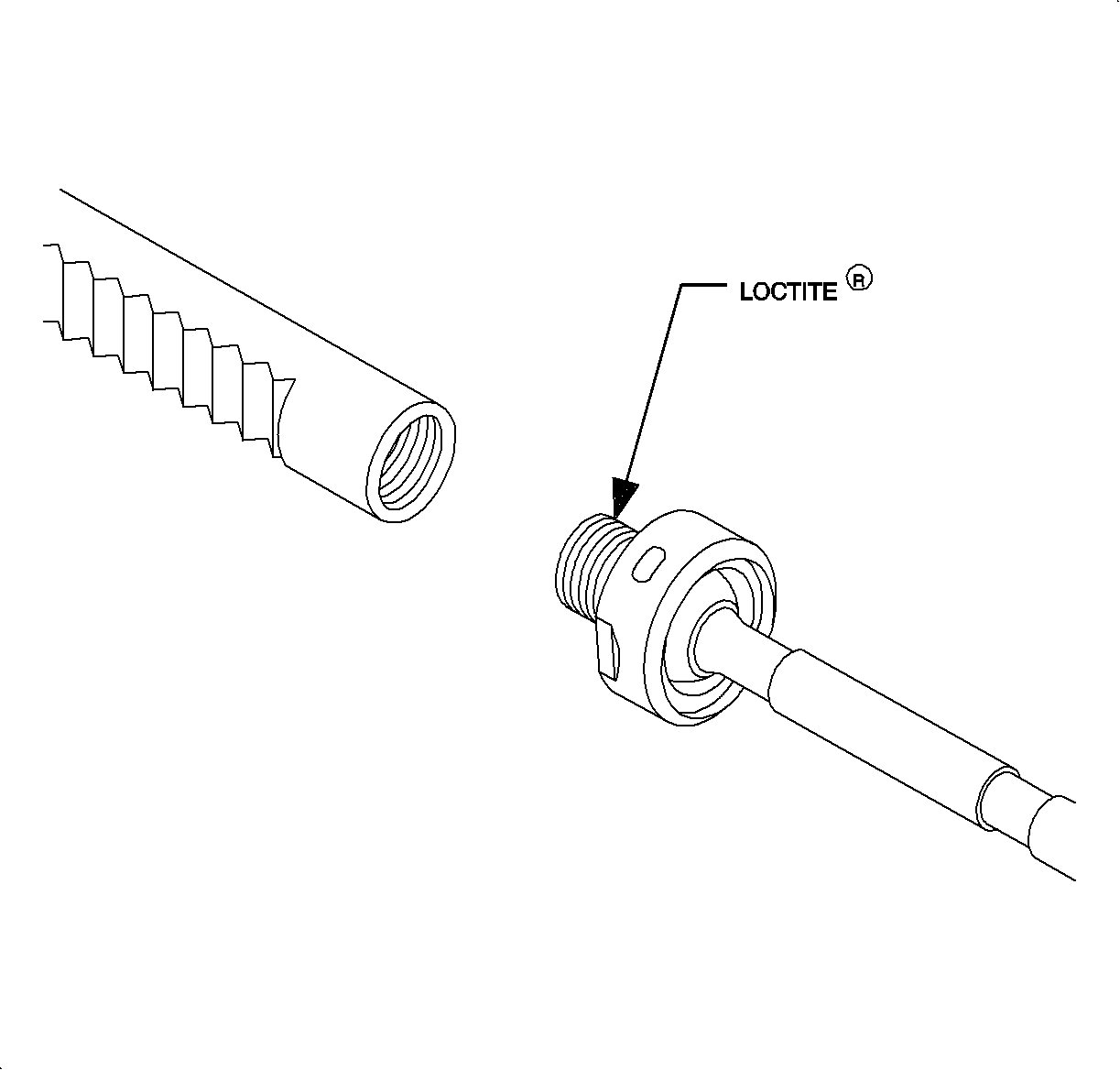
Important: Threads must be clean prior to Loctite application. Make sure Loctite or equivalent) container expiration date has not passed. Do not use too much Loctite (or equivalent). Use only enough to evenly coat threads
Notice: Steering gear must be held stationary during inner tie rod installation to prevent steering gear damage.
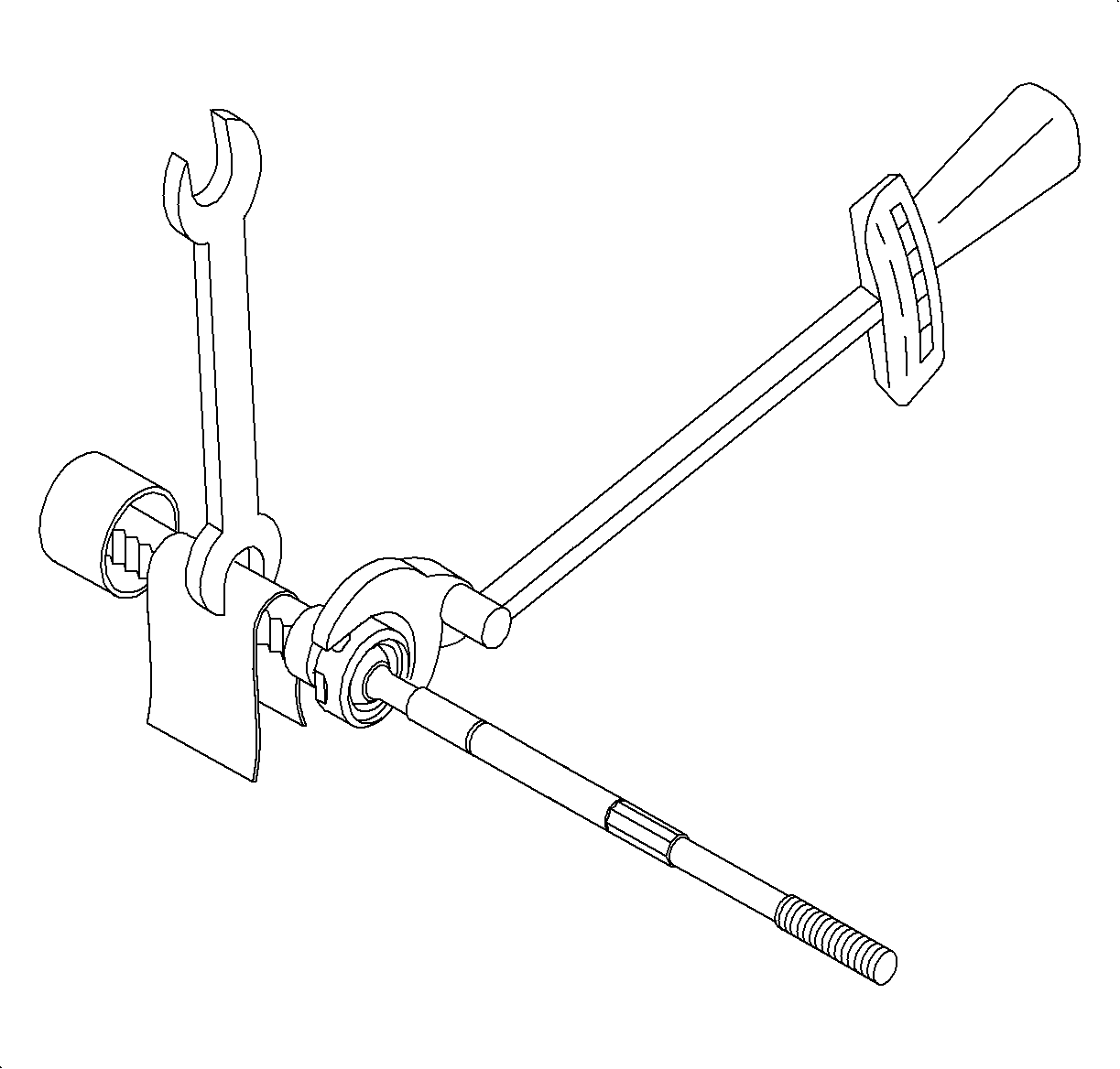
Tighten
Torque: 95 N·m(70 lb ft)
Notice: Before installing wheels, remove rust or corrosion from wheel mounting surface and brake rotors/drums. Failure to do so can cause wheel nuts to loosen in service.

Tighten
Torque: 140 N·m (103 lb ft)
