Flywheel Inspection Procedures

| Subject: | Flywheel Inspection Procedures |
| Models: | 1991-1999 Saturn vehicles equipped with MP2 or MP3 manual transaxles |
Purpose
When replacing the clutch disc and pressure plated due to normal component wear, it may be necessary to replace the flywheel assembly to ensure an effective friction surface. This bulletin provides guidelines to help determine whether a flywheel should be replaced.
Note: If the flywheel is resurfaced, the bolts connecting the flywheel to the crankshaft may, over time, come in contact with the springs located on the 3rd design clutch disc as it normally wears. (Refer to bulletin 98-T-24A or 98-T-XX for further information on updated clutch components.) This will cause the springs and bolts to wear and become damaged. This could lead to potential damaged clutch components and/or crankshaft. Therefore, Saturn highly recommends that flywheels no longer be resurfaced.
Important: Prior to performing the following service procedure, check the vehicle service history to determine whether the flywheel has already been resurfaced. If the flywheel has been resurfaced previously and the clutch disc is being replaced with the long travel damper disc (P/N 21120564), it is necessary to replace the flywheel with chamfered flywheel (P/N 21120535) and the following "Flywheel Inspection: procedure is no longer necessary.
Flywheel Inspection Procedure

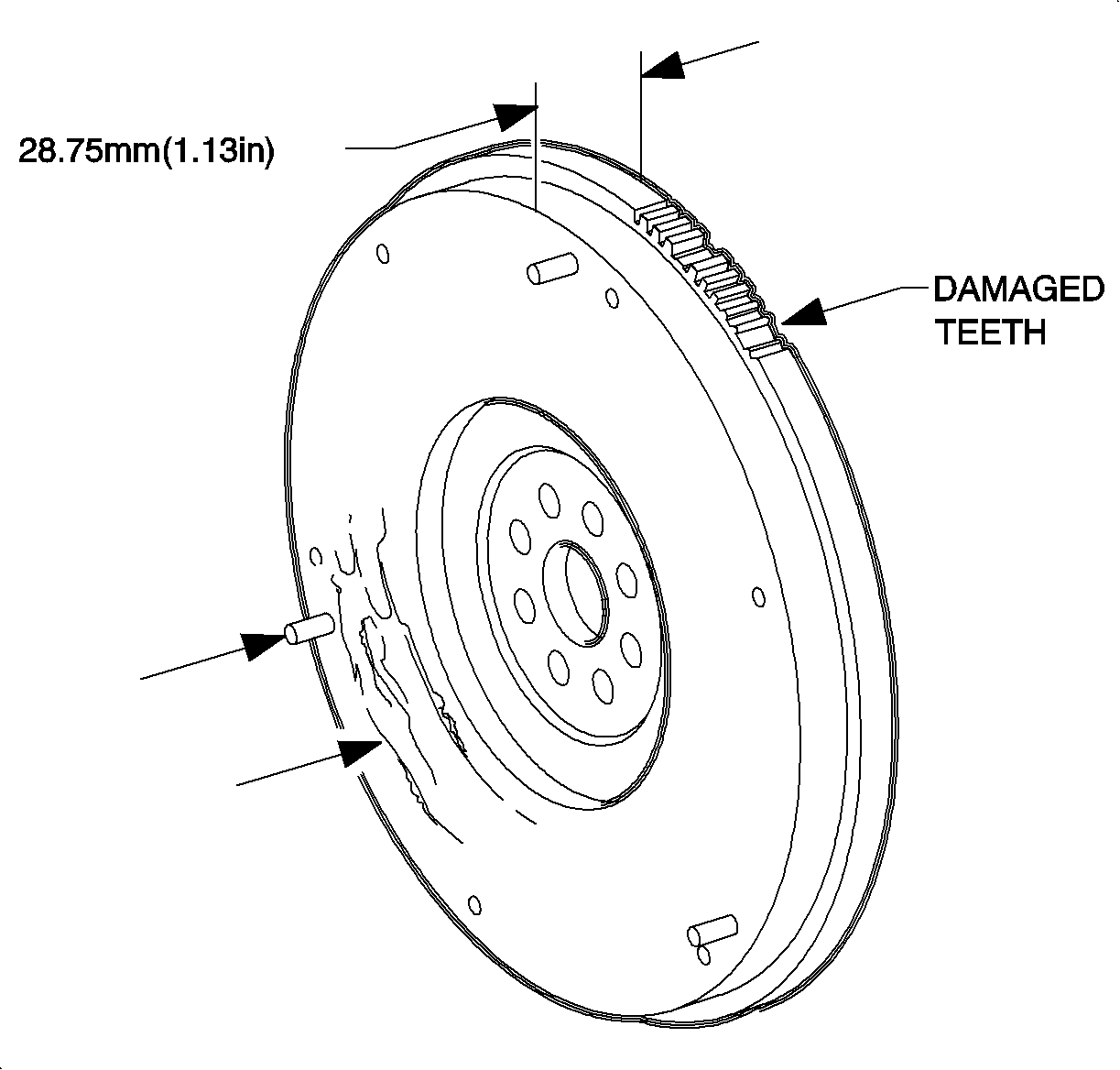
15. Inspect the flywheel ring gear for wear or damage to the teeth.
| • | If the flywheel ring gear is damaged, replace the flywheel. |
| • | If the flywheel ring gear is not damaged, proceed to next step. |
16. Check flywheel clutch-disc-contact surface for corrosion, chatter marks, scoring, cracking or overheating (indicated by blue discoloration).
Important: Random black spots on the friction surface of the flywheel are normal.
| • | If any of these conditions exist, replace the flywheel. |
| • | If none of these conditions exist, proceed to next step. |

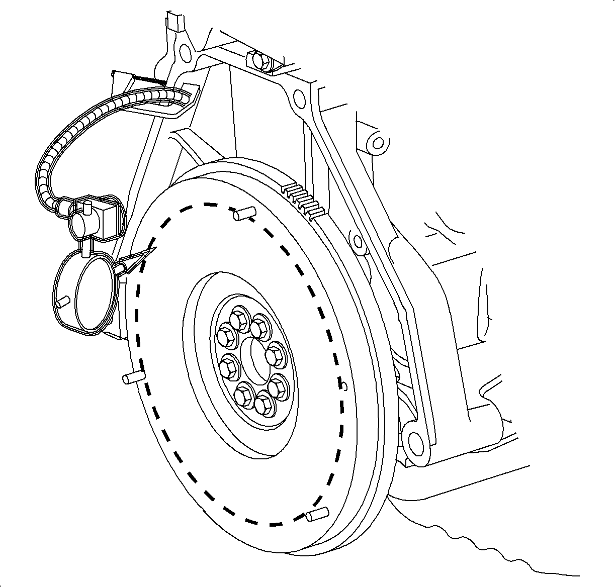
17. Using a dial indicator, measure flywheel runout. Push the crankshaft forward to take up thrust bearing clearance. Measure the runout at a diameter just inside the pressure plated bolt holes for at least two revolutions.
Maximum Runout: 0.15 mm (0.006 in.)
| • | If the flywheel runout is not within specification, replace the flywheel. |
| • | If the flywheel runout is within specification, proceed to next step. |

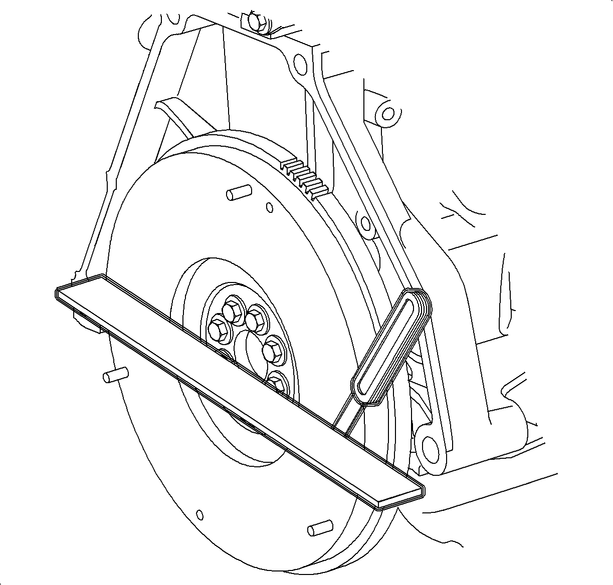
18. Using a straight edge, check the flywheel for warpage.
Maximum Warpage: 0.15 mm (0.006 in.)
| • | If the flywheel warpage is not within specification, replace the flywheel. |
| • | If the flywheel warpage is within specification, proceed to next step. |
19. Using a micrometer, measure flywheel thickness in three places around the circumference of the flywheel. All measurements must be made at the same distance in from the edge of the flywheel and at equal distances from each other.
Minimum Flywheel Thickness: 28.75 mm (1.13 in.)
| • | If the flywheel thickness is not within specification, replace the flywheel. |
| • | If the flywheel thickness is within specification, proceed to next step. |

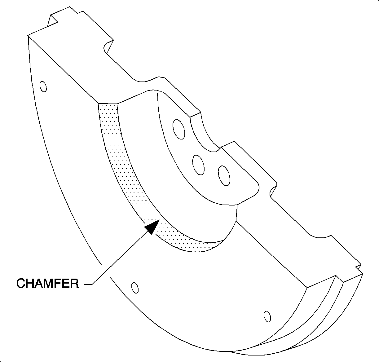
20. Inspect inside edge of friction surface toward center of flywheel for a chamfer.
| • | If flywheel does not have a chamfer, then a chamfer must be machined into flywheel. Refer to bulletin 98-T-24A or 98-T-XX for flywheel chamfering procedures. |
| • | If flywheel does have a chamfer and all other inspection procedures are within specification with no flywheel damage evident, then flywheel damage evident, then flywheel does not need to be replaced. |
Parts Requirements
21120535 -- Asm - Flywheel (2nd design with chamfer)
Warranty Information
To receive credit for this repair during the warranty coverage period, submit a claim through the Saturn Dealer System using the appropriate Electronic Labor Time Guide and Labor Operation Code K0800 with the following Add Condition:
Add: To replace flywheel (if necessary) -- 0.2 hrs
