Service Information Regarding Upper Engine Mount Assembly

| Subject: | Service Information Regarding Upper Engine Mount Assembly - Due to changes in the Parts Requirement, this bulletin has been revised and supersedes bulletin 01-T-30, which should be discarded. |
| Models: | 1992-2002 Saturn S-Series Vehicles |
| Attention: | Please distribute this bulletin to: Parts Manager and all Technicians |
Purpose
This bulletin contains new sag measurement and replacement procedures for upper engine mounts.
The first design upper engine mount (P/N 2101285) is being reintroduced into production and will be the only mount used to service all 1992-2002 Saturn S-Series vehicles. This first design mount requires longer engine front cover studs (P/N 21008003).
Refer to "Engine Mount Sag Measurement Procedures" in this bulletin to verify the need for upper engine mount assembly replacement. If replacement is required, refer to "Engine Mount Assembly Removal Procedure, " "Front Cover Stud Installation Procedure," and "Engine Mount Assembly Installation Procedure" in this bulletin.
Engine Mount Sag measurement Procedure (First Design Engine Mount)
- Inspect the vehicle to see if current top engine mount is a first design mount. Refer to the following illustration.
- Using two 150 mm (6 in.) scales or a 150 mm (6 in.) scale and a suitable straight edge, measure engine mount assembly as shown in the First Design Mount Illustration.
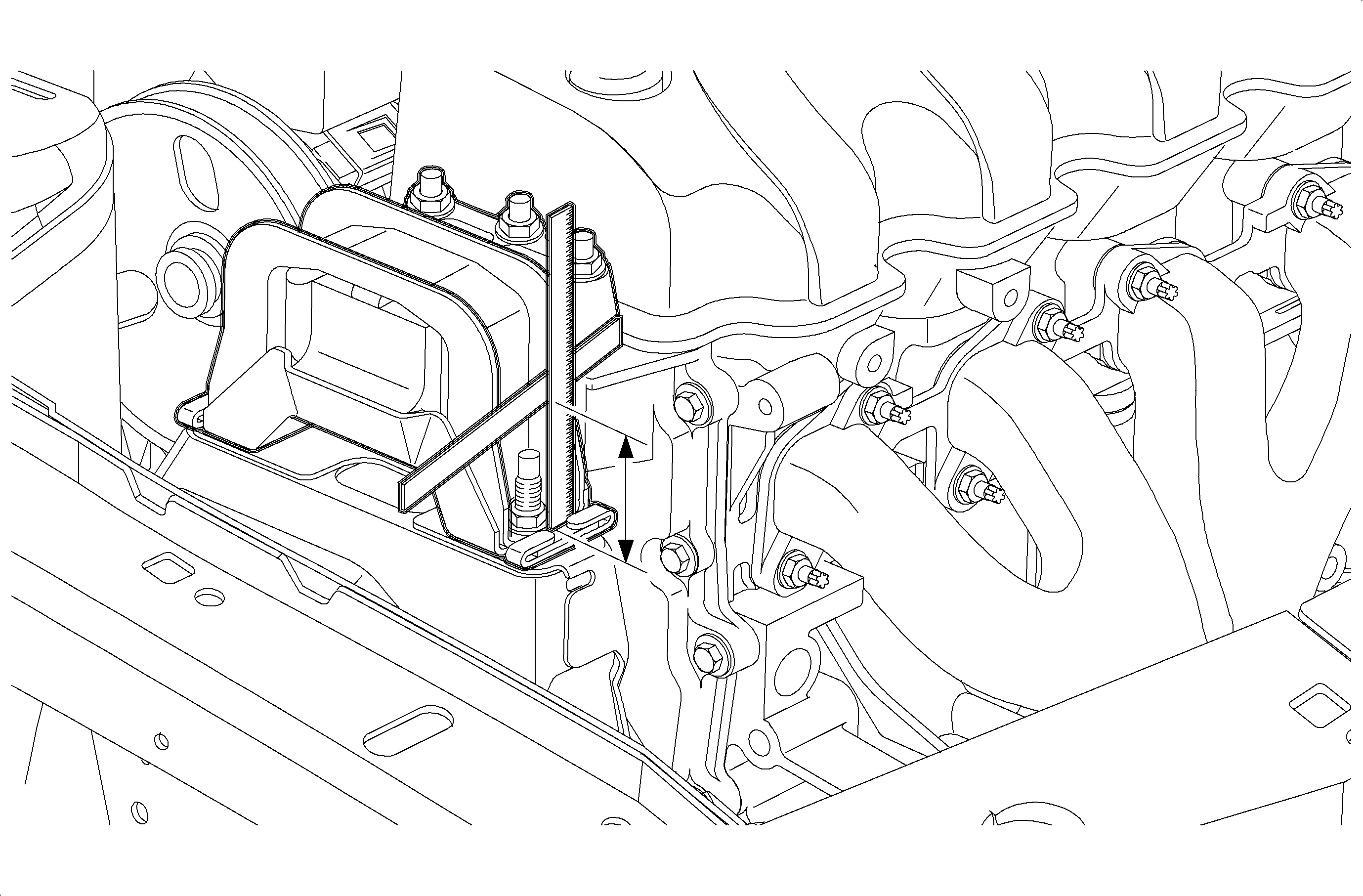
Important: The measurement procedure in Step 2 of this procedure can be used to measure sag on both first and second design engine mounts.
| • | If measurement is equal to or less than 39 mm (1 17/32 in.), proceed to "Engine Mount Assembly Removal Procedure" in this bulletin and replace engine mount assembly. |
| • | If measurement is greater than 39 mm (1 17/32 in.), engine mount assembly does not require replacement. |
Engine Mount Sag measurement Procedure (Second Design Engine Mount)
- Inspect the vehicle to see if current top engine mount is a second design mount. Refer to the following illustration.
- Measure gap in mount at location shown in the Second Design Mount Illustration. A 2 mm (5/64 in.) Allen wrench or hex key can be used as a go/no go gauge for this measurement.
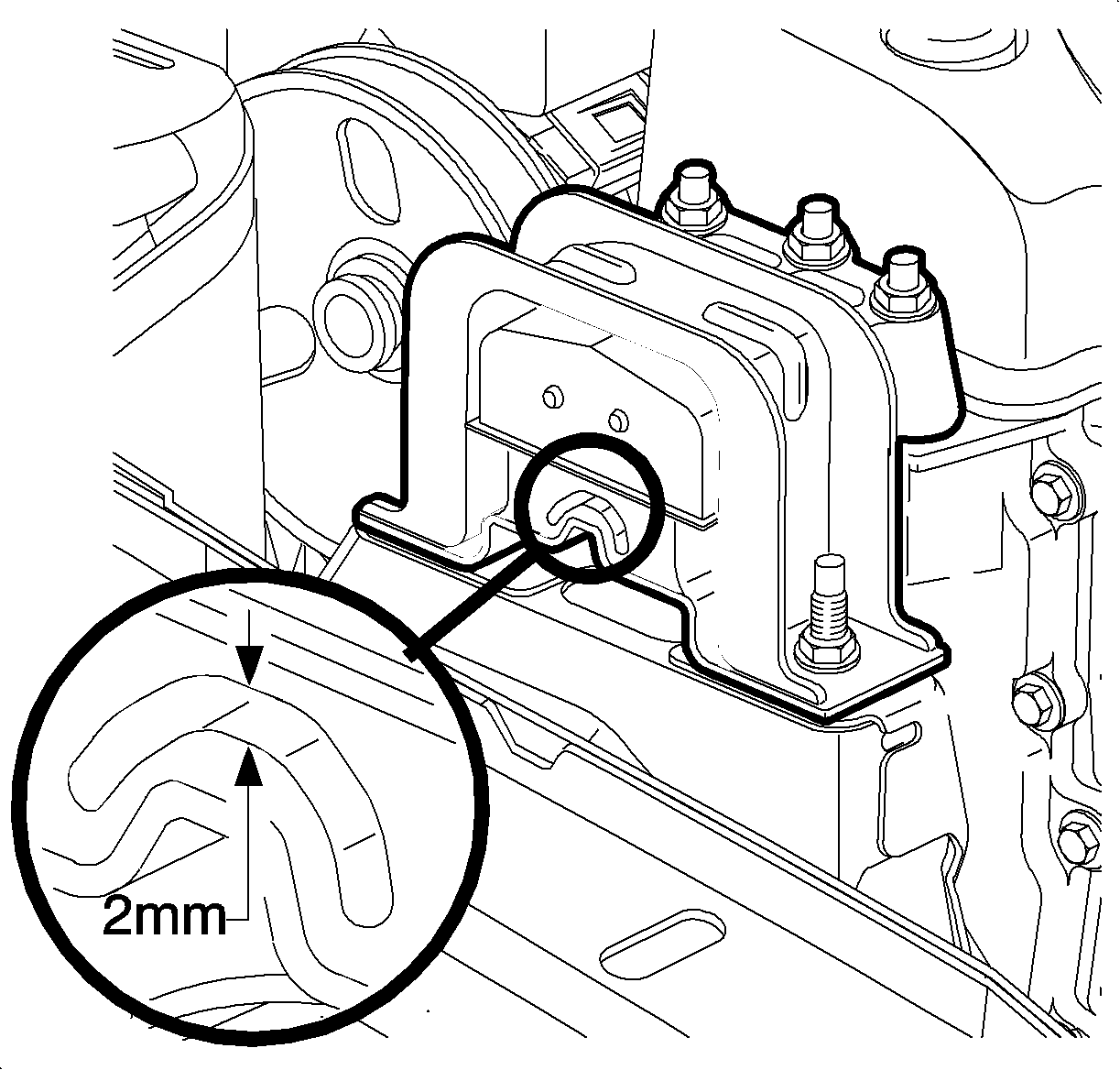
Important: The measurement procedure in step 2 can only be used for the second design mount.
| • | If tool does not fit in gap, proceed to "Engine Mount Assembly Removal Procedure" in this bulletin and replace engine mount assembly. |
| • | If tool fits in gap, engine mount assembly does not require replacement. |
Engine Mount Assembly Removal Procedure
- Remove the 2 engine mount-to-midrail bracket fasteners.
- Place a floor jack under the engine oil pan. Use a block of wood between the oil pan and jack. Raise the powertrain just enough to unload the mount. The engine is raised enough when there is clearance between the mount and the midrail bracket.
- Remove the 3 engine mount-to-front cover fasteners, and remove the engine mount.
- Remove engine mount.
- If vehicle has second design mount, remove three engine mount cover studs and discard.
- Proceed to one of the following sections in this bulletin, as appropriate:
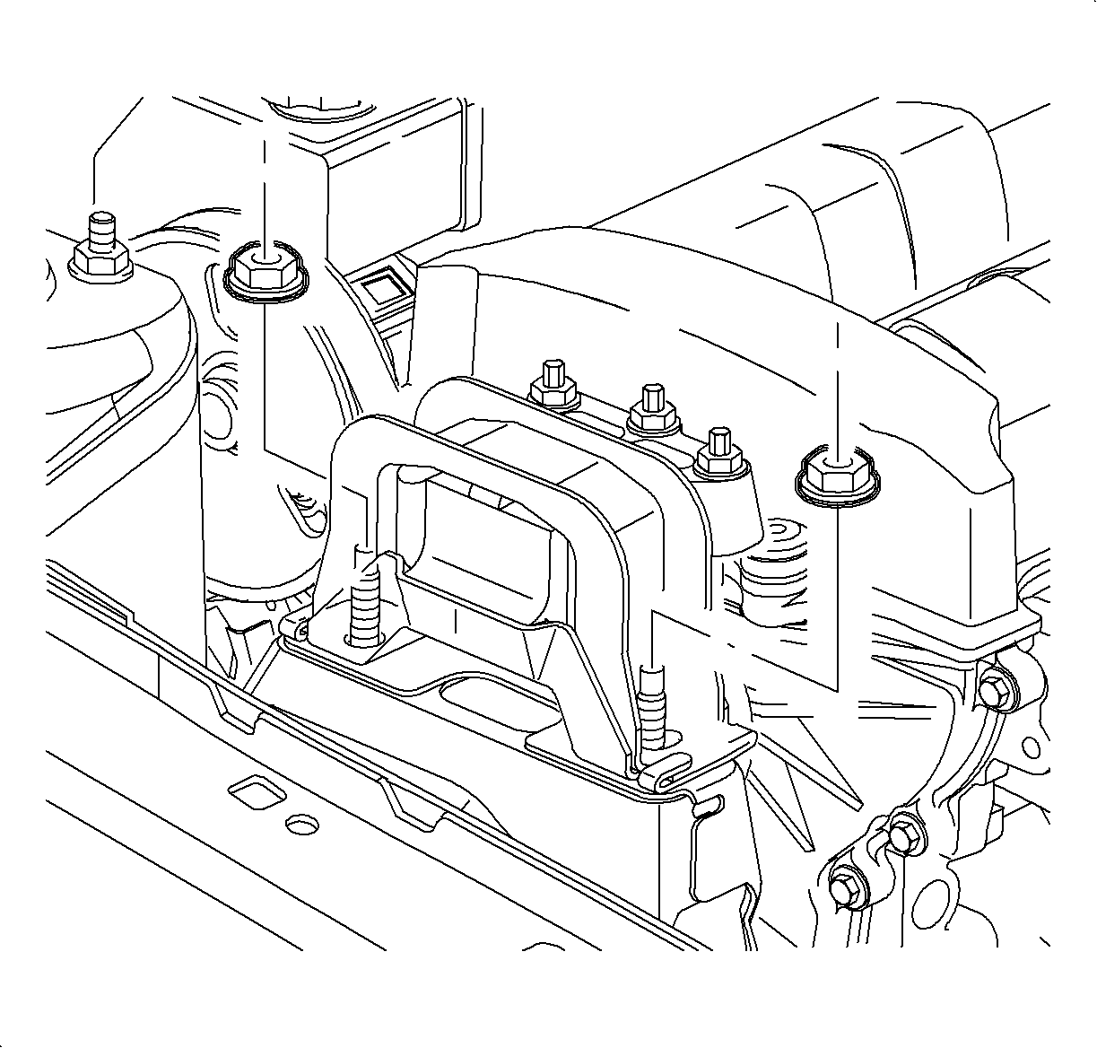
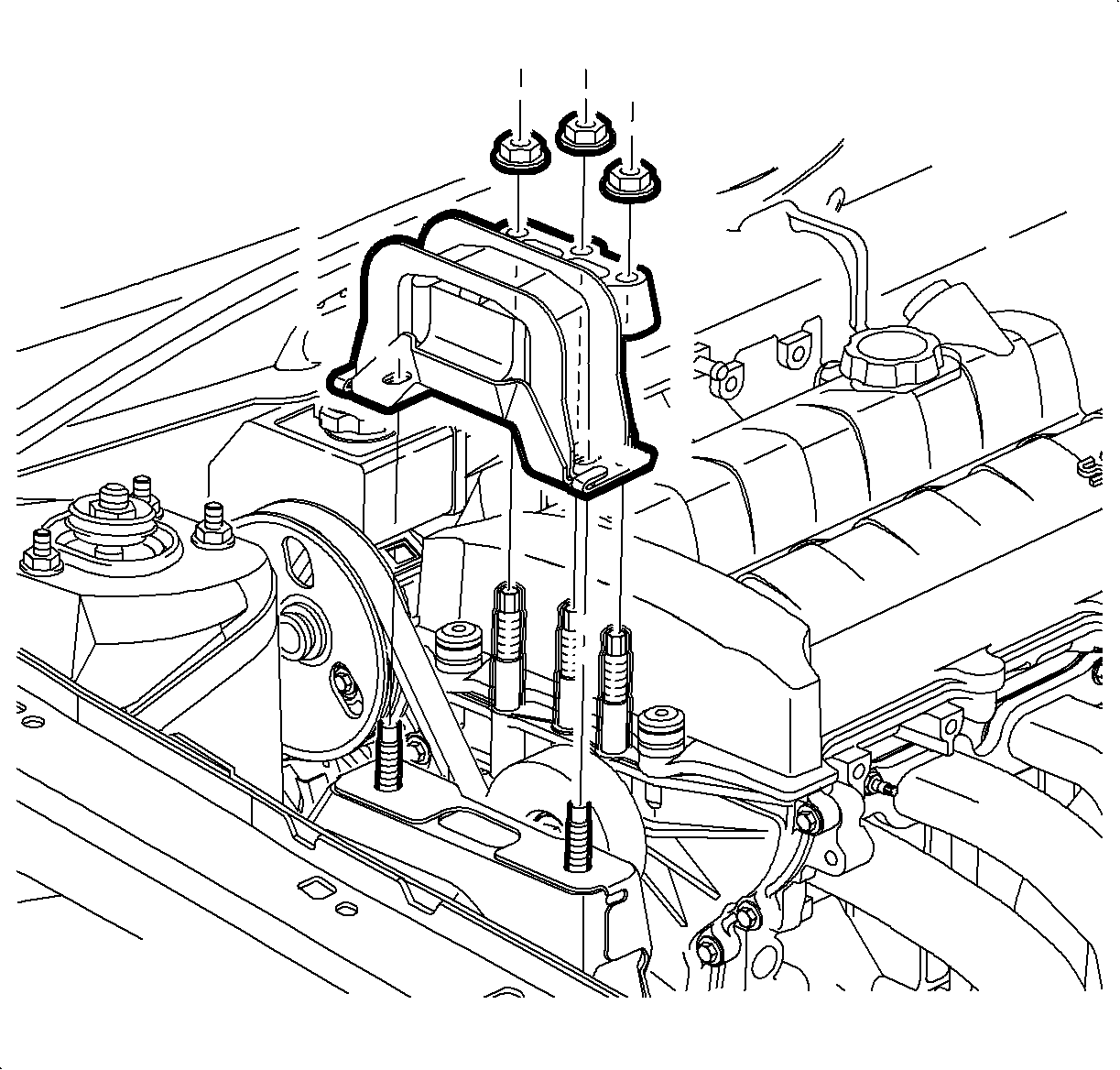
Notice: If the engine mount front cover stud turns or comes out during nut removal, the stud must be fully installed prior to installing the mount and/or nut. Damage to the front cover may occur if the stud is driven with the nut and does not sufficiently engage the front cover threads.
| • | If vehicle is equipped with first design mount and no studs turned or come out during removal, proceed to "Engine Mount Assembly Installation Procedure." |
| • | If vehicle is equipped with first design mount and studs turned loose during removal, proceed to "Front Cover Stud Installation Procedure." |
| • | If vehicle is equipped with second design mount, proceed to "Front Cover Stud Installation Procedure." |
Front Cover Stud Installation Procedure
- If vehicle was equipped with second design mount, the front cover studs previously removed cannot be reused. Obtain new, longer front cover studs (P/N 21008003). If vehicle was equipped with first design mount, the original studs can be reused.
- Apply Loctite 242® or equivalent to 6-8 middle threads of clean front cover studs.
- Apply Loctite 242® or equivalent to the threads of the holes in the engine front cover using a cotton tipped applicator keeping the top 2 threads clean.
- Install the studs into the front cover.
- Clean the excess threadlocker from the front cover and studs.
- Proceed to "Engine Mount Assembly Installation Procedure" in this bulletin.
Notice: If the engine mount front cover stud turns or comes out during nut removal, the stud must be fully installed prior to installing the mount and/or nut. Damage to the front cover may occur if the stud is driven with the nut and does not sufficiently engage the front cover threads.
Important: If the vehicle has first design mount, the front cover studs can be reused with new mount. If the vehicle has second design mount, new longer front cover studs are required with new mount.
Notice: Do not overapply threadlocker or allow it to accumulate in bottom of hole. The front cover could be damaged when the stud is installed.
Important: If reinstalling a previously installed stud, the threads must be thoroughly cleaned before applying threadlocker. If installing a new stud, the stud may or may not have a pre-applied threadlocker. The front cover stud hole must be thoroughly cleaned using a 10 mm x 1.5 tap to clean the threads and compressed air to remove particles from the stud hole.
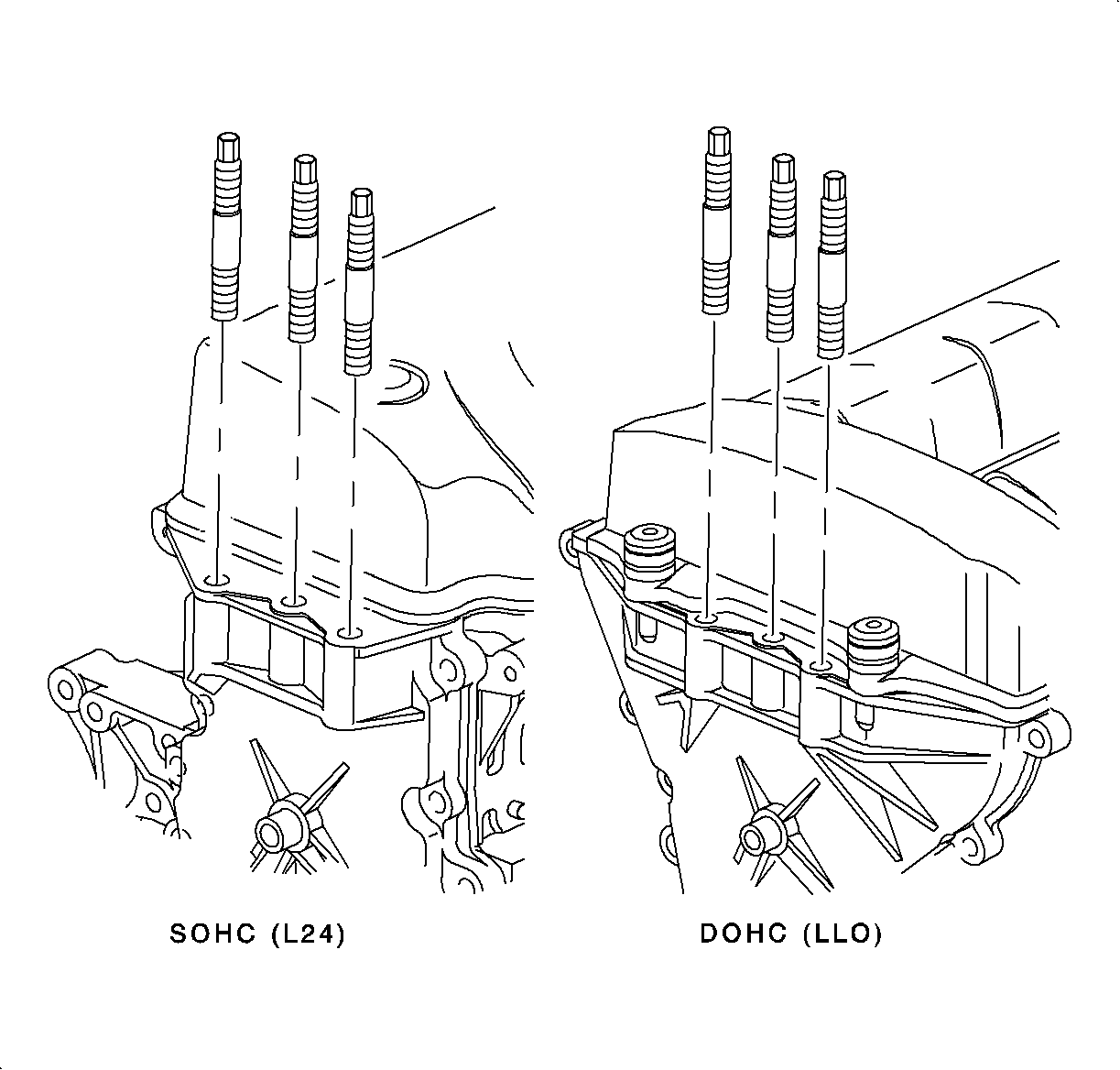
Important: The engine mount front cover stud torque specification is new and should be used for repairs on all 1992-2002 S-Series front cover studs.
Tighten
Tighten the engine mount front cover studs to 10 N·m (89 lb in).
Engine Mount Assembly Installation Procedure
- Obtain replacement parts. Refer to "Parts Requirements" in this bulletin.
- Position the engine mount to front cover and install NEW nuts.
- Lower the powertrain completely.
- Install NEW engine mount-to-midrail bracket nuts.
- Raise the vehicle on a hoist.
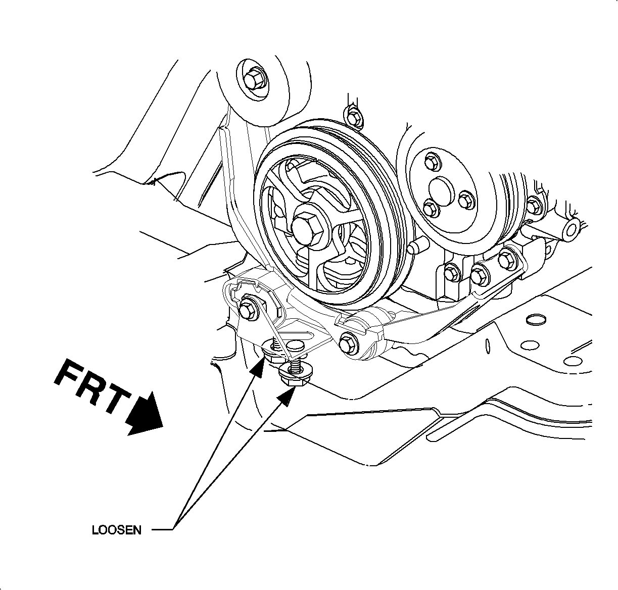
- Loosen the 2 engine strut bracket-to-cradle fasteners to remove any fore/aft preload from the engine strut.
- Tighten the 2 engine strut bracket-to-cradle fasteners.
- Lower the vehicle from the hoist.

Important: If equipped, install ground strap to stud on intake manifold side before installing new nut.
Tighten
Tighten the engine mount-to-front cover nuts to 50 N·m (37 lb ft).

Notice: When lowering the powertrain, it will be necessary to guide the mount over the midrail bracket studs to prevent damage to the stud threads.
Tighten
Tighten the engine mount-to-midrail bracket nuts to 50 N·m (37 lb ft).
Caution: Make sure the vehicle is properly supported and squarely positioned prior to lifting. To help avoid personal injury when a vehicle is on a hoist, provide additional support for the vehicle on the opposite end from which components are to be removed.
Tighten
Tighten the engine strut bracket-to-cradle nuts to 50 N·m (37 lb ft).
Parts Information
Part Description | 1st Design | 2nd Design | Quantity Required |
|---|---|---|---|
ENGINE MOUNT ASM | 21012185 | N/A* | 1 |
STUD-ENG MT | 21008003 | 210075845 | 3 |
NUT-ENG MT | 21006320 | 21006320 | 5 |
LOCTITE 242 | 21485277 | 21485277 | 1 |
*Second design engine mount is no longer available | |||
Warranty Information
To receive credit for this repair during the warranty coverage period, submit a claim through the Saturn Dealer System for J1504 (Mount Torque Axis - Replace), or if another procedure is performed, refer to the appropriate Electronic Labor Time Guide for the correct Labor Operation Code and Time.
Loctite 242 (part number 21485277) may be claimed as material using net item type "M." Claims received in the amount of $4.62 ($3.55 dealer cost plus 30% parts allowance) will be accepted. Claims exceeding the material mount will be returned with return reason 143 - material amount > maximum allowed. Retailer "B" authorization code will not override this return reason.
