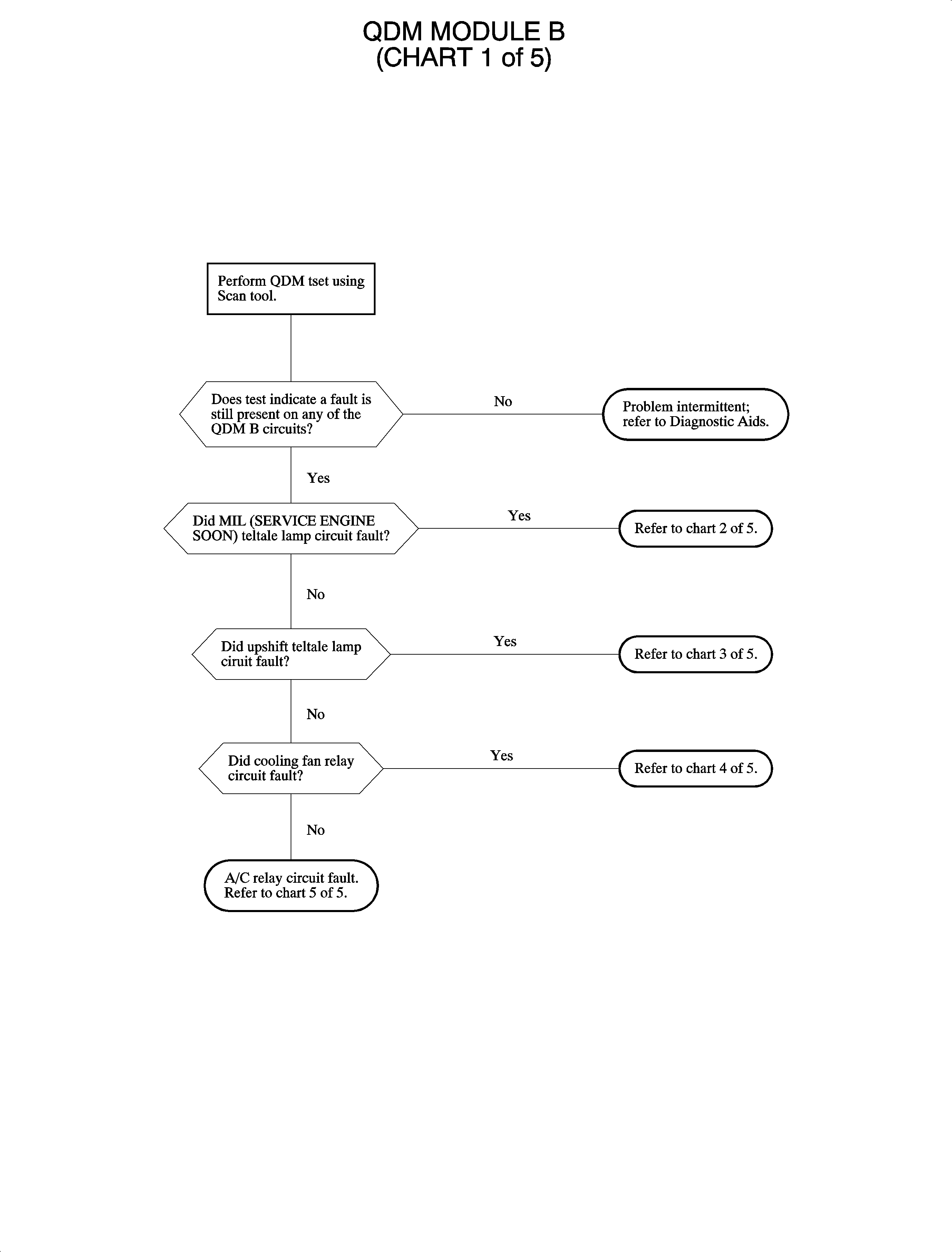
DTC P1650 or P1651 QDM Module B
Circuit Description
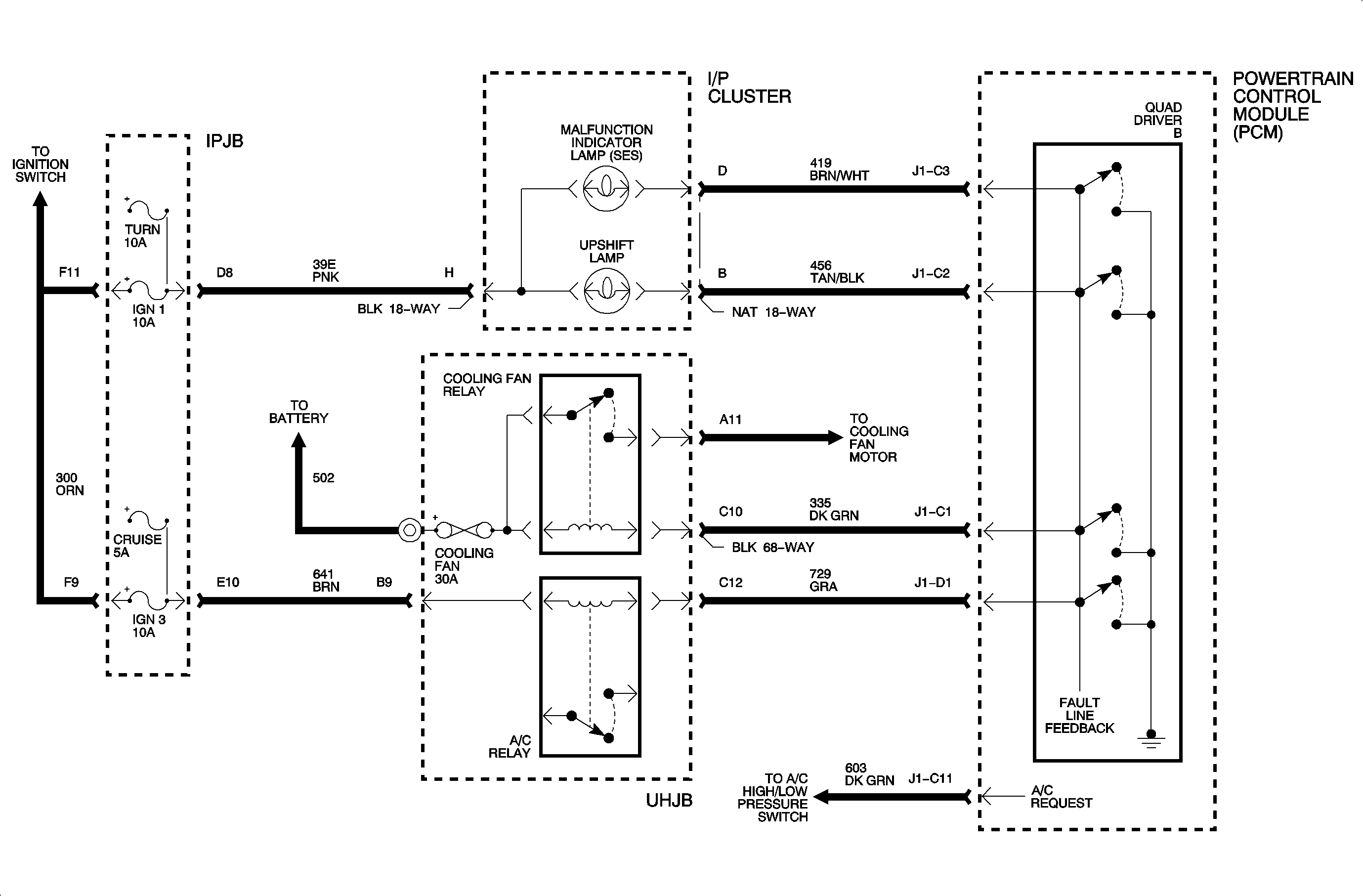
A quad driver module (QDM) is an electronic switch which completes a ground circuit when switched ON. The QDM independently controls 4 separate outputs. A load is connected between battery voltage and the QDM allowing the QDM driver to control the output. Each QDM has fault detection logic which compares QDM driver input and output voltages. The logic expects to measure less than 3 volts when the QDM driver is ON and greater than 7 volts when OFF. Each QDM has only 1 fault line that will detect a fault on any of the 4 outputs. The scan tool can be used to cycle each output ON and OFF. The scan tool can also perform an automated test which will isolate the faulty output circuit.
Conditions for Setting the DTC
Important: The QDM circuit is continuously checked when the engine is running.
DTC P1650 and/or P1651 will set if:
| • | There is an open, short to ground, or short to voltage on any of the QDM output circuits. |
| • | The MIL, service engine soon, telltale lamp circuit |
| • | The upshift lamp circuit |
| • | The cooling fan relay circuit |
| • | The A/C relay circuit |
| • | The fault is detected for 5 seconds for DTC P1651. |
| • | The fault is detected for 20 seconds for DTC P1650. |
Diagnostic Aids
| • | If 1 output is bad, the PCM will shut down only that QDM output and not the entire quad driver unless the quad driver reaches its thermal limit, short to voltage. At this time it will turn all 4 quad driver outputs OFF. When the quad driver cools down, it will turn back ON and this process will start over. |
| • | A shorted or open, relay, or bulb can cause a DTC P1650 and/or P1651 to set. |
Use the Saturn service stall system, if available, to diagnose the quad driver circuits or use a scan tool and perform an off-board QDM test.
For example, if the MIL, service engine soon telltale lamp, is OFF, the PCM expects to measure 12 volts on the circuit line. If the circuit is open, 0 volts will be measured on the circuit and the fault will be displayed. However, if the lamp is turned ON, the PCM expects to measure 0 volts on the circuit, and will not detect a fault. This causes an intermittent problem because the lamp is not continuously ON.
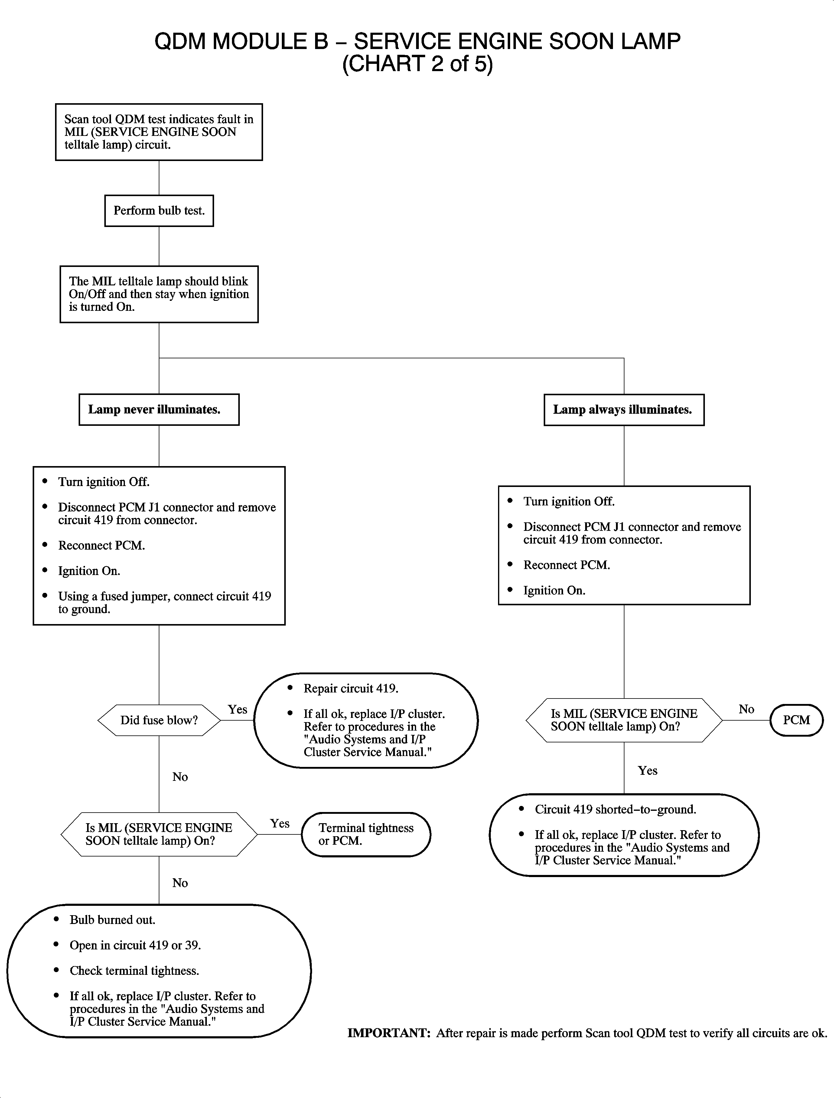
DTC P1650 or P1651 QDM Module B - Service Engine Soon
Circuit Description
A quad driver module (QDM) is an electronic switch which completes a ground circuit when switched ON. The QDM independently controls 4 separate outputs. A load is connected between battery voltage and the QDM allowing the QDM driver to control the output. Each QDM has fault detection logic which compares QDM driver input and output voltages. The logic expects to measure less than 3 volts when the QDM driver is ON and greater than 7 volts when OFF. Each QDM has only 1 fault line that will detect a fault on any of the 4 outputs. The scan tool can be used to cycle each output ON or OFF. The scan tool can also perform an automated test which will isolate the faulty output circuit.
Conditions for Setting the DTC
Important: The QDM circuit is continuously checked when the engine is running.
DTC P1650 and/or P1651 will set if there is an open, short to ground, or short to voltage on the QDM output MIL, service engine soon, telltale lamp circuit.
Diagnostic Aids
| • | If 1 output is bad, the PCM will shut down only that QDM output and not the entire quad driver unless the quad driver reaches its thermal limit, short to voltage. At this time it will turn all 4 quad driver outputs OFF. When the quad driver cools down, it will turn back ON and this process will start over. |
| • | Check the 10 amp IGN 1 fuse in the IPJB. |
| • | A shorted or open, relay, or bulb can cause a DTC P1650 and/or P1651 to set. |
Use the Saturn service stall system, if available, to diagnose the quad driver circuits or use a scan tool and perform an off-board QDM test.
For example, if the MIL, service engine soon telltale lamp, is OFF, the PCM expects to refer to 12 volts on the circuit line. If the circuit is open, 0 volts will be measured on the circuit and the fault will be displayed. However, if the lamp is turned ON, the PCM expects to measure 0 volts on the circuit, and will not detect a fault. This causes an intermittent problem because the lamp is not continuously ON.
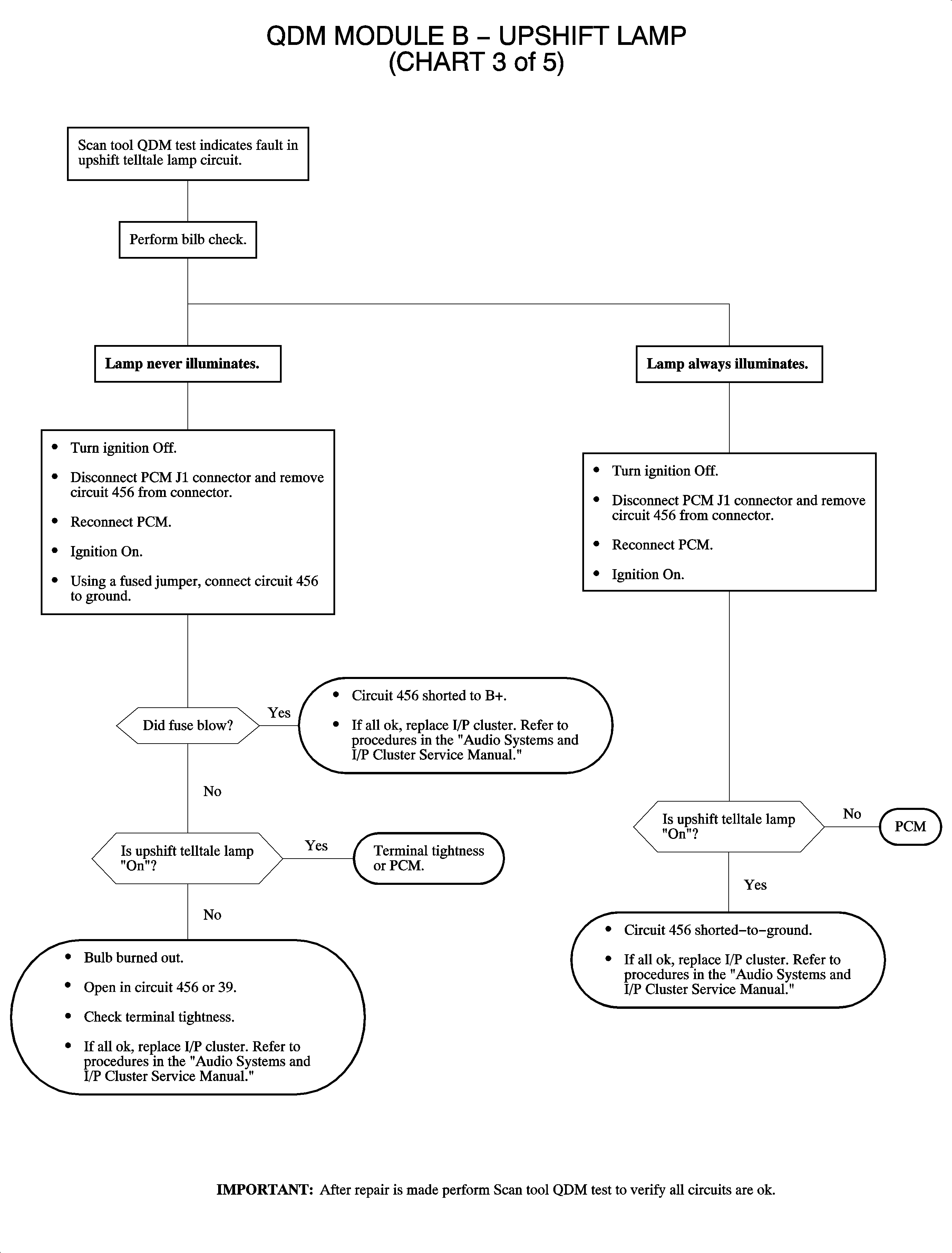
DTC P1650 or P1651 QDM Module B - Upshift Lamp
Circuit Description
A quad driver module (QDM) is an electronic switch which completes a ground circuit when switched ON. The QDM independently controls 4 separate outputs. A load is connected between battery voltage and the QDM allowing the QDM driver to control the output. Each QDM has fault detection logic which compares QDM driver input and output voltages. The logic expects to measure less than 3 volts when the QDM driver is ON and greater than 7 volts when OFF. Each QDM has only 1 fault line that will detect a fault on any of the 4 outputs. The scan tool can be used to cycle each output ON or OFF. The scan tool can also perform an automated test which will isolate the faulty output circuit.
Conditions for Setting the DTC
Important: The QDM circuit is continuously checked when the engine is running.
DTC P1650 and/or P1651 will set if there is an open, short to ground, or short to voltage on the QDM output upshift telltale lamp circuit.
Diagnostic Aids
| • | If 1 output is bad, the PCM will shut down only that QDM output and not the entire quad driver unless the quad driver reaches its thermal limit, short to voltage. At this time it will turn all 4 quad driver outputs OFF. When the quad driver cools down, it will turn back ON and this process will start over. |
| • | Check the 10 amp IGN 1 fuse in the IPJB. |
| • | A shorted or open, relay, or bulb can cause a DTC P1650 and/or P1651 to set. |
Use the Saturn service stall system, if available, to diagnose the quad driver circuits or use a scan tool and perform an off-board QDM test.
For example, if the MIL, service engine soon telltale lamp, is OFF, the PCM expects to refer to 12 volts on the circuit line. If the circuit is open, 0 volts will be measured on the circuit and the fault will be displayed. However, if the lamp is turned ON, the PCM expects to measure 0 volts on the circuit, and will not detect a fault. This causes an intermittent problem because the lamp is not continuously ON.
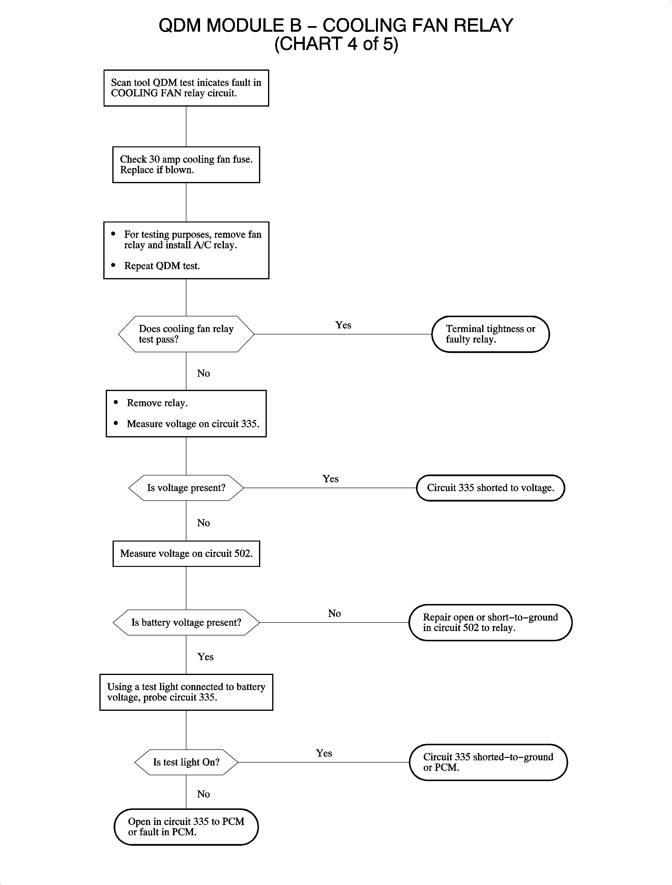
DTC P1650 or P1651 QDM Module B - Cooling Fan Relay
Circuit Description
A quad driver module (QDM) is an electronic switch which completes a ground circuit when switched ON. The QDM independently controls 4 separate outputs. A load is connected between battery voltage and the QDM allowing the QDM driver to control the output. Each QDM has fault detection logic which compares QDM driver input and output voltages. The logic expects to measure less than 3 volts when the QDM driver is ON and greater than 7 volts when OFF. Each QDM has only 1 fault line that will detect a fault on any of the 4 outputs. The scan tool can be used to cycle each output ON or OFF. The scan tool can also perform an automated test which will isolate the faulty output circuit.
Conditions for Setting the DTC
Important: The QDM circuit is continuously checked when the engine is running.
DTC P1650 and/or P1651 will set if there is an open, short to ground, or short to voltage on the QDM output upshift telltale lamp circuit.
Diagnostic Aids
| • | If 1 output is bad, the PCM will shut down only that QDM output and not the entire quad driver unless the quad driver reaches its thermal limit, short to voltage. At this time it will turn all 4 quad driver outputs OFF. When the quad driver cools down, it will turn back ON and this process will start over. |
| • | The coolant fan relay resistance is 70-90 ohms. |
| • | Check the 30 amp COOL FAN fuse in the UHJB. |
| • | A shorted or open, relay, or bulb can cause a DTC P1650 and/or P1651 to set. |
Use the Saturn service stall system, if available, to diagnose the quad driver circuits or use a scan tool and perform an off-board QDM test.
For example, if the MIL, service engine soon telltale lamp, is OFF, the PCM expects to refer to 12 volts on the circuit line. If the circuit is open, 0 volts will be measured on the circuit and the fault will be displayed. However, if the lamp is turned ON, the PCM expects to measure 0 volts on the circuit, and will not detect a fault. This causes an intermittent problem because the lamp is not continuously ON.
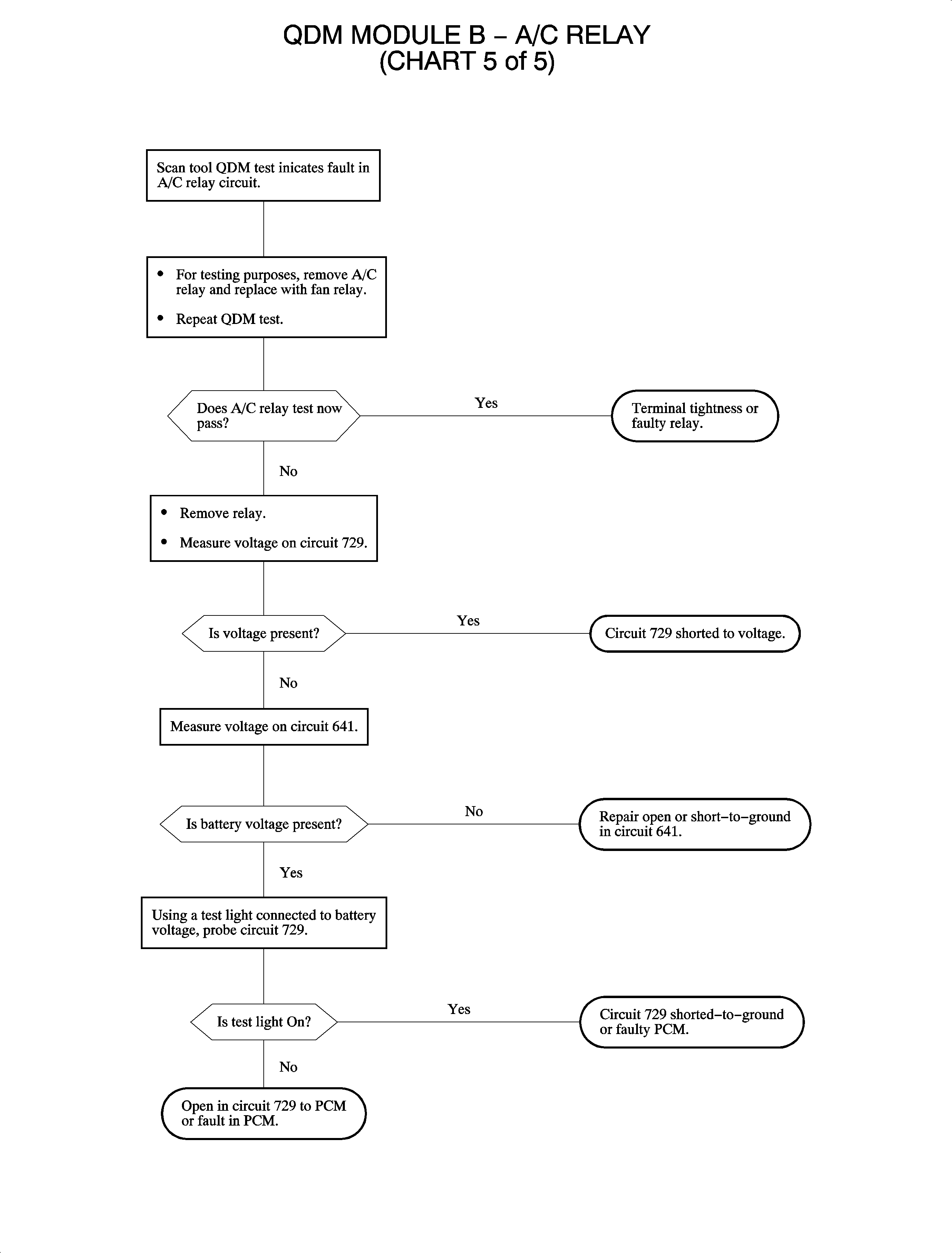
DTC P1650 or P1651 QDM Module B - A/C Relay
Circuit Description
A quad driver module (QDM) is an electronic switch which completes a ground circuit when switched ON. The QDM independently controls 4 separate outputs. A load is connected between battery voltage and the QDM allowing the QDM driver to control the output. Each QDM has fault detection logic which compares QDM driver input and output voltages. The logic expects to measure less than 3 volts when the QDM driver is ON and greater than 7 volts when OFF. Each QDM has only 1 fault line that will detect a fault on any of the 4 outputs. The scan tool can be used to cycle each output ON or OFF. The scan tool can also perform an automated test which will isolate the faulty output circuit.
Conditions for Setting the DTC
Important: The QDM circuit is continuously checked when the engine is running.
DTC P1650 and/or P1651 will set if there is an open short to ground or short to voltage on the QDM output A/C relay circuit.
Diagnostic Aids
| • | If 1 output is bad, the PCM will shut down only that QDM output and not the entire quad driver unless the quad driver reaches its thermal limit, short to voltage. At this time, it will turn all 4 quad driver outputs OFF. When the quad driver cools down it will turn back ON and this process will start over. |
| • | Check the 7.5 amp IGN 3 fuse in the IPJB. |
| • | The A/C relay resistance is 70-90 ohms. |
| • | Check the 30 amp COOL FAN fuse in the UHJB. |
| • | A shorted open, relay, or bulb can cause a DTC P1650 and/or P1651 to set. |
Use the Saturn service stall system, if available, to diagnose the quad driver circuits or use a scan tool and perform an off-board QDM test.
For example, if the MIL, service engine soon telltale lamp, is OFF, the PCM expects to refer to 12 volts on the circuit line. If the circuit is open, 0 volts will be measured on the circuit and the fault will be displayed. However, if the lamp is turned ON, the PCM expects to measure 0 volts on the circuit, and will not detect a fault. This causes an intermittent problem because the lamp is not continuously ON.