The powertrain control module (PCM) uses pulses from the crankshaft position
sensor to determine the position and RPM of the engine at various degrees of crankshaft
rotation. The PCM bases misfire diagnostics on the principle that crankshaft velocity
will increase as each cylinder contributes its power input. Under certain conditions,
the PCM will monitor crankshaft velocity variation in a series of 200 revolution
tests. If 20-100 percent of the revolutions fail, a catalyst damaging
misfire has occurred. If 2-19 percent of the revolutions fail, an emission
related misfire has occurred. The malfunction indicator light (MIL) (SERVICE ENGINE
SOON telltale) will flash when an active catalyst damaging misfire occurs on the
first drive cycle. The MIL will be ON steady if an emission related misfire occurs
after two consecutive drive cycles. The MIL will turn OFF after three consecutive
passed drive cycles meeting the same misfire criteria or 80 passed drive
cycles if the criteria could not be met. DTC P0300 sets when a specific or
random cylinder misfire has occurred.
DTC Parameters
DTC P0300 will set if specific or random cylinder misfires have been detected
after a series of 200 revolution tests when:
| • | The engine speed is between 562-5500 RPM. |
| • | The engine coolant temperature (ECT) is greater than -7°C (20°F).
If the ECT is less than -7°C (20°F), the PCM will wait until the ECT
is greater than 20°C (68°F). |
| • | The ignition voltage is between 8-18 volts. |
| • | The fuel level is greater than 3.8 L (1 gallon). |
| • | Crank learn = YES. If crank learn = NO, engine run time must be greater
than 20 seconds to enable misfire. |
| • | No 5 volt reference, cam, crankshaft position (CKP), ECT, fuel
trim, idle air control (IAC) valve, intake air temperature (IAT), manifold absolute
pressure (MAP), throttle position (TP) or vehicle speed DTCs have been set |
DTC P0300 diagnostic runs continuously once the above conditions have been met.
DTC P0300 is a type B DTC.
Diagnostic Aids
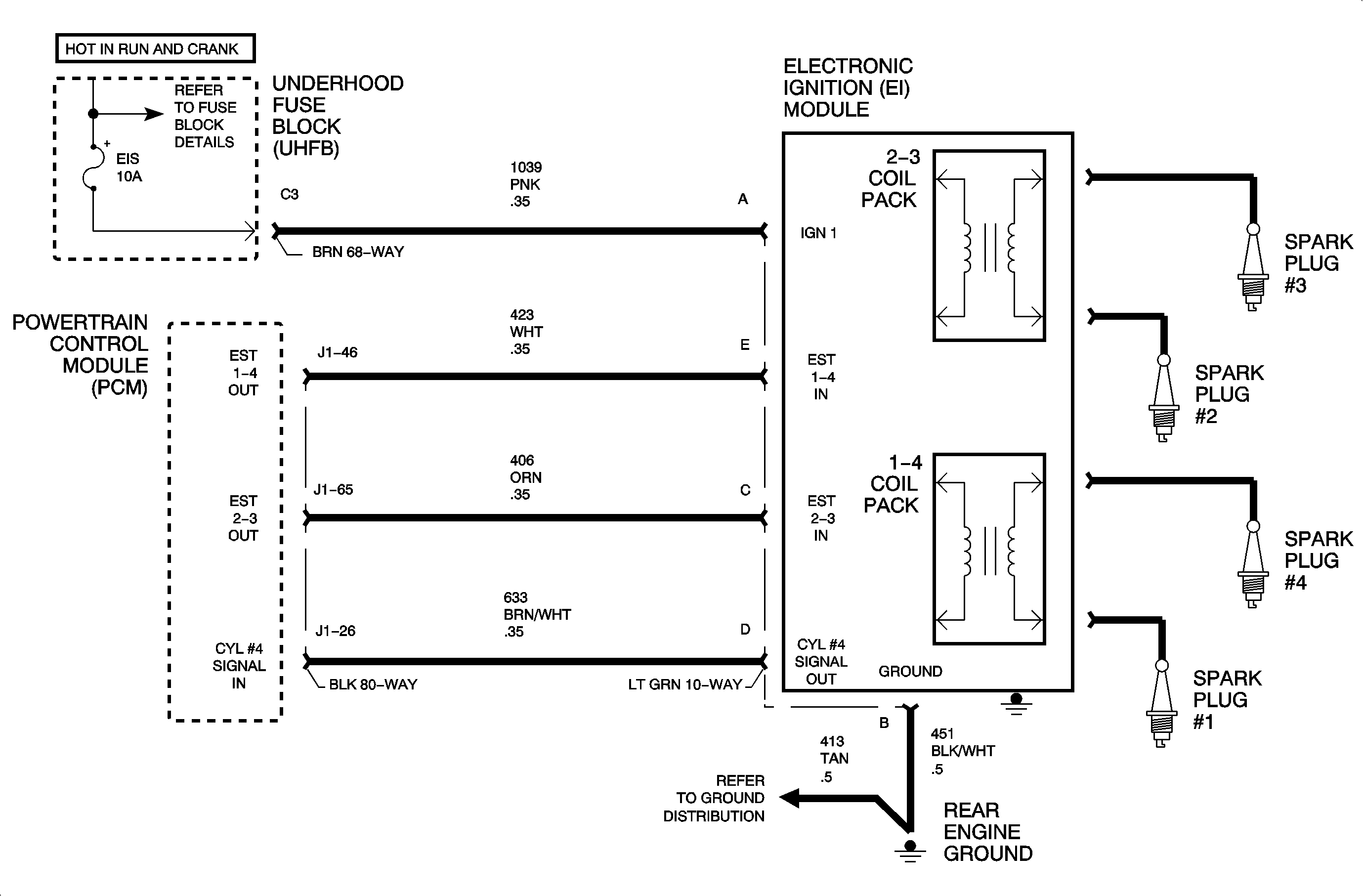
Important: If an ignition control (IC) circuit, fuel injector or exhaust gas recirculation
(EGR) DTC is set, those should be diagnosed first because they may be the cause
of the misfire.
If vehicle has had prior replacement of a PCM or crankshaft, the crankshaft
must be relearned.
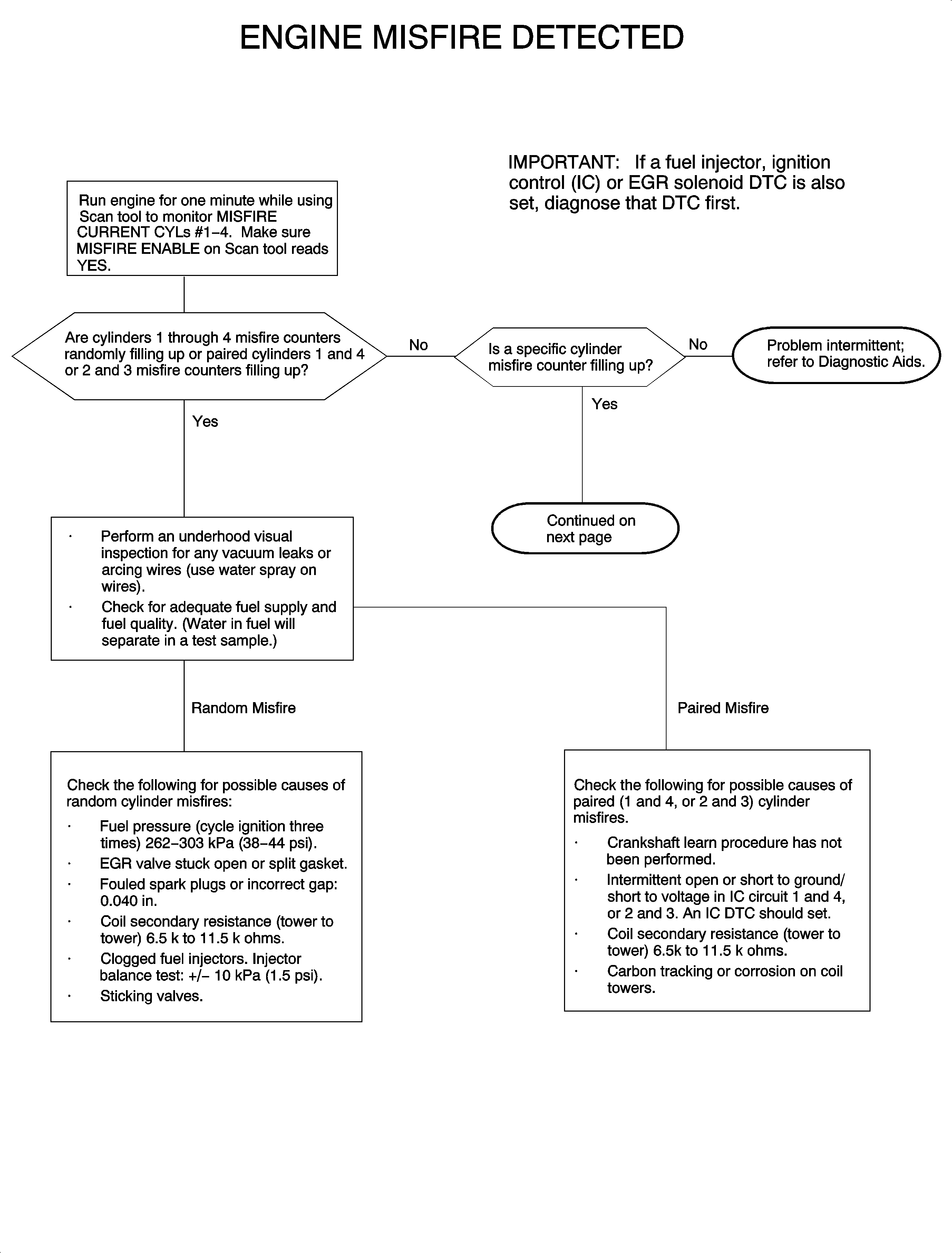
Use DATA DISPLAY information to check MISFIRE HISTORY CYL. #1-4
to determine whether the engine has a specific or random misfire.
Spraying water on wires provides a good path for current to flow to ground on
an arcing wire.
Use a scan tool to monitor MISFIRE CURRENT CYL #1-4 while simulating
different engine load conditions in the stall. The scan tool current misfire counter
should pick up intermittent misfire conditions.
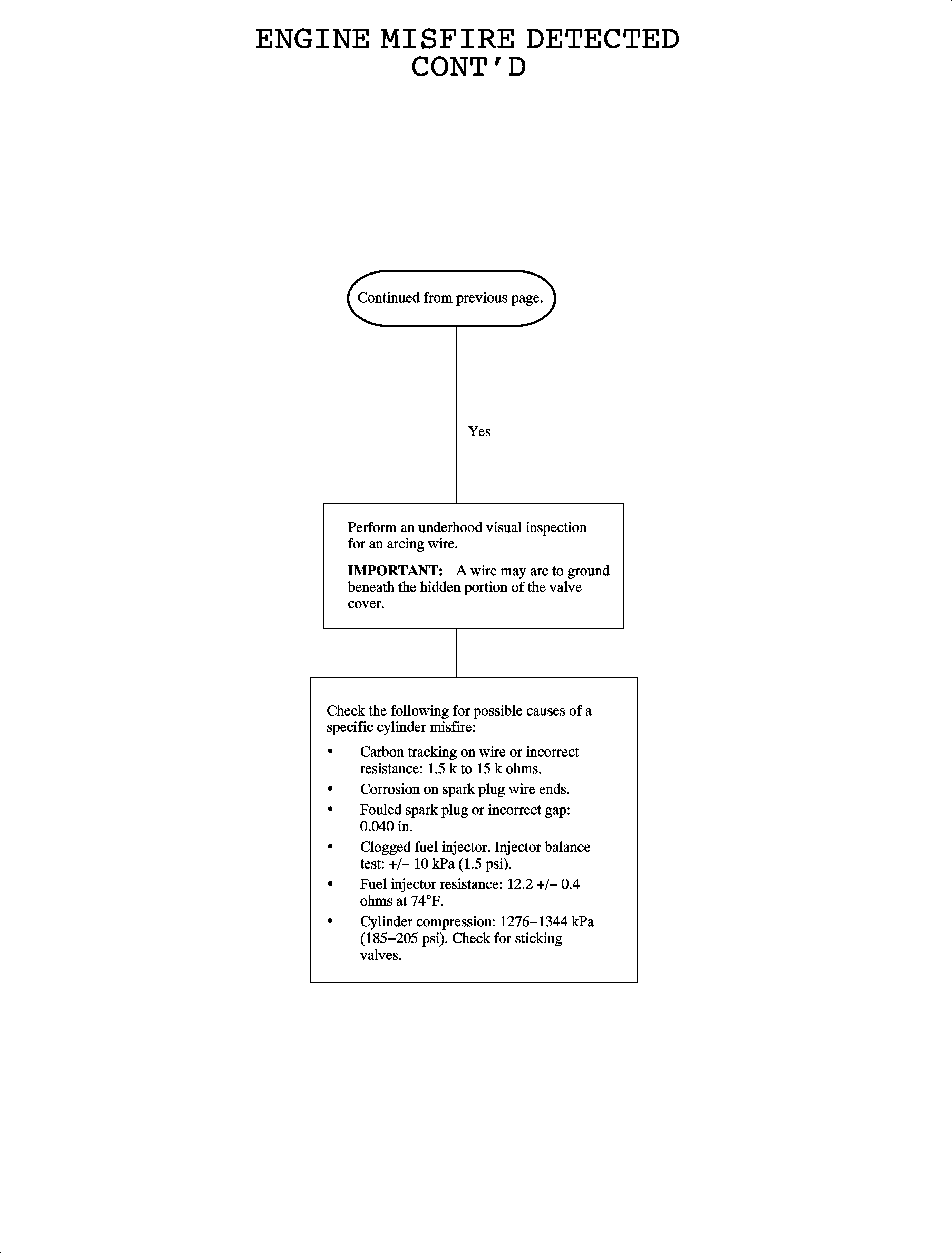
| • | Fuel injector resistance: 12.2 +/- 0.4 ohms at 23°C (74°F) |
| • | Wire resistance: 1.5k-15k ohms |
| • | Spark plug gap: 0.040 in |
| • | Coil pack tower to tower secondary resistance: 6.5k-11.5k ohms |
| • | Wire position on coil packs |


