Tools Required
SA9159S Front Wheel Bearing
Remover/Installer
Disassembly Procedure
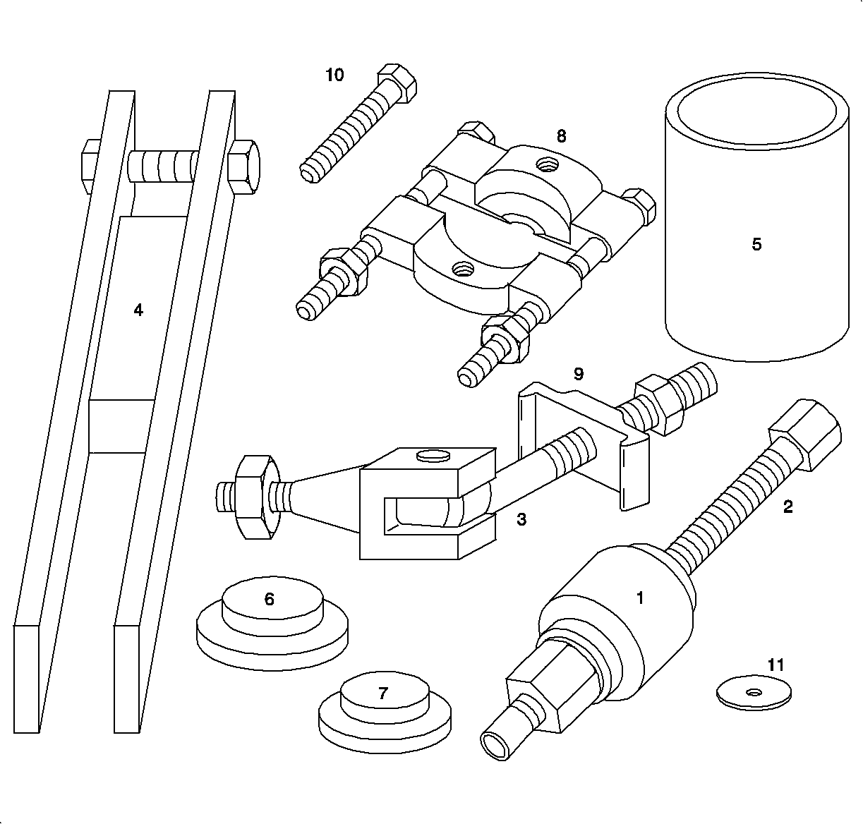
- Remove the steering knuckle/hub assembly from
the vehicle.
- Remove the ABS wheel speed sensor from the knuckle.
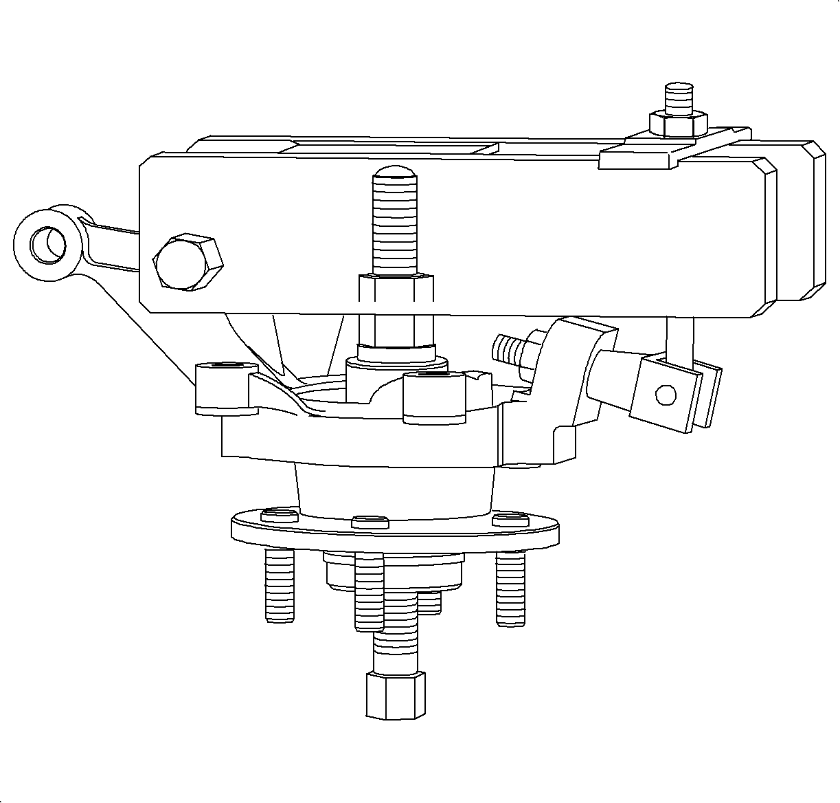
Important: If the hub or bearing is removed from the knuckle, a new bearing must be used
during assembly.
- Assemble theSA9159S
(or equivalent)
with following part numbers:
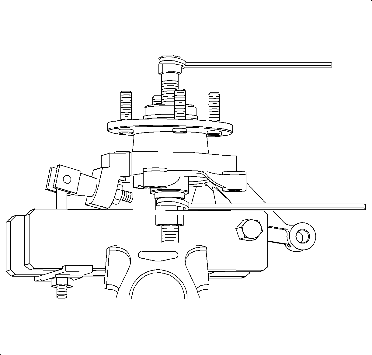
- Secure the entire setup in a vice (by the bridge)
as shown in the illustration.
- While holding the hub driver with a wrench, tighten the hub driver screw
to extract the hub.
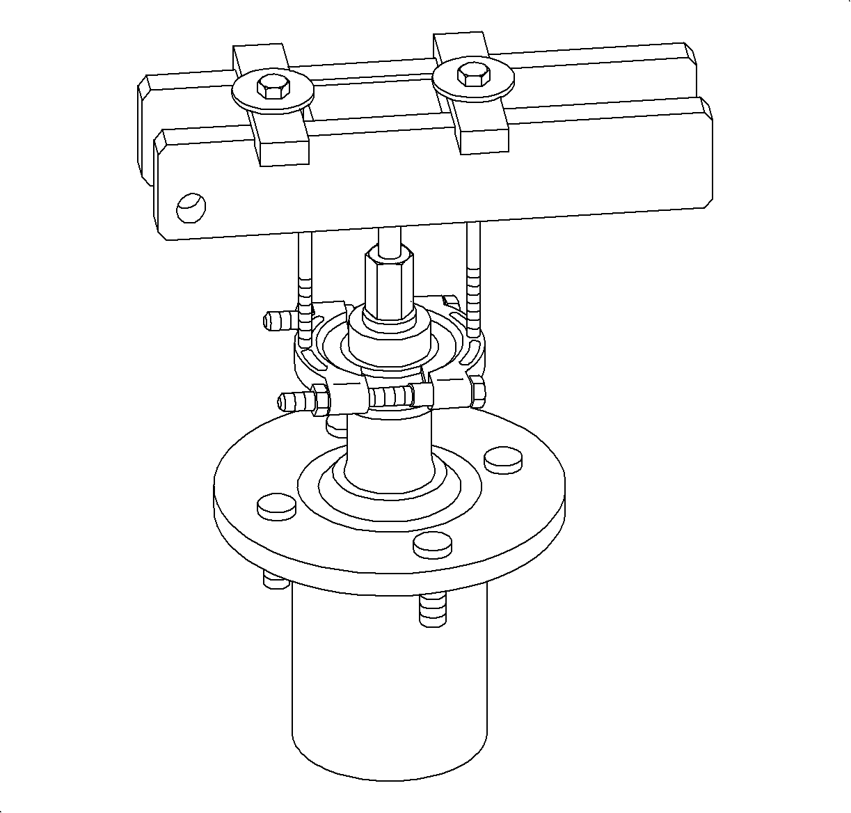
- If the inner race of bearing is pulled out with
the hub in the previous step, remove the race from the hub using the following part
numbers:
| • | 9 - 2 bridge retainer plates |
| • | Inspect the hub at the bearing location for pitting, scoring, wear, or corrosion.
Replace if necessary. |
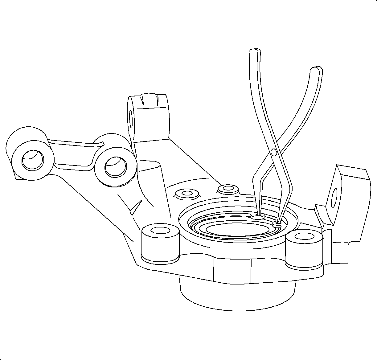
- Remove the steering knuckle from the vice.
- Remove the bridge retainer and the bridge.
- Remove the bearing retainer snap ring.
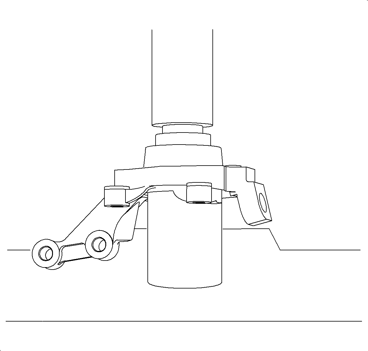
- Place the knuckle/bearing assembly in a shop
press as shown in illustration, using the following part numbers:
| • | 5 - Knuckle support tube |
- Press out the bearing. Inspect the bore of knuckle for pitting, scoring
wear, or corrosion. If damage cannot be easily cleaned up with light sanding, replace
the knuckle.
Assembly Procedure
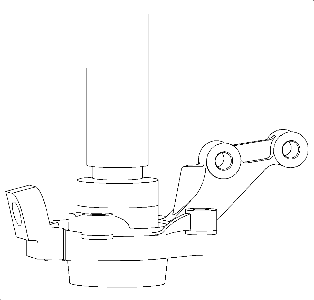
- Using the large driver (part number 6),
press in the new bearing, as shown in the illustration, until seated.
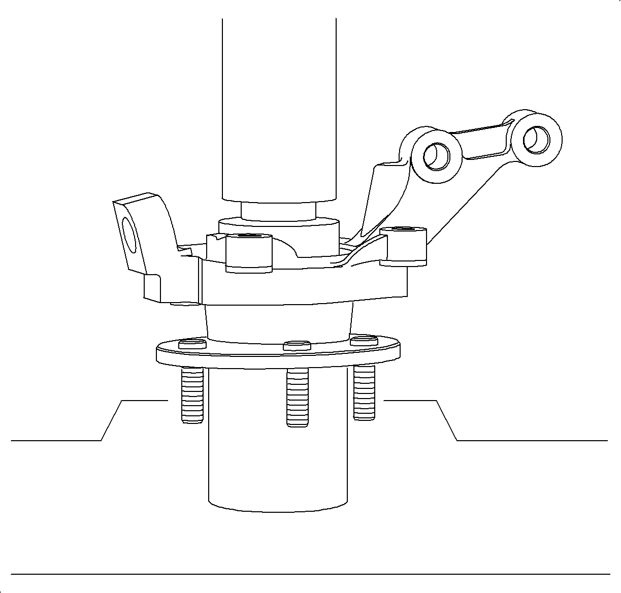
Important: When performing this operation, the small driver (part number 7) must
be used to support the bearing inner race with its small (pilot) side facing towards
the press, away from the bearing.
- Press in the hub as shown in illustration, using part the numbers:
| • | 5 - Knuckle support tube |
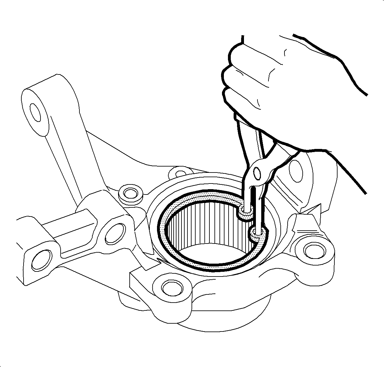
- Install the bearing retainer snap ring.
- Install the ABS wheel speed sensor into the knuckle with the fastener.
Tighten
Tighten the ABS Wheel Speed Sensor to 8 N·m (6 lb ft).


