Temperature Control Cable Replacement LHD Only
Removal Procedure
- Loosen the upper trim panel:
- Loosen the steering column filler panel screws.
- Remove the left endcap assembly.
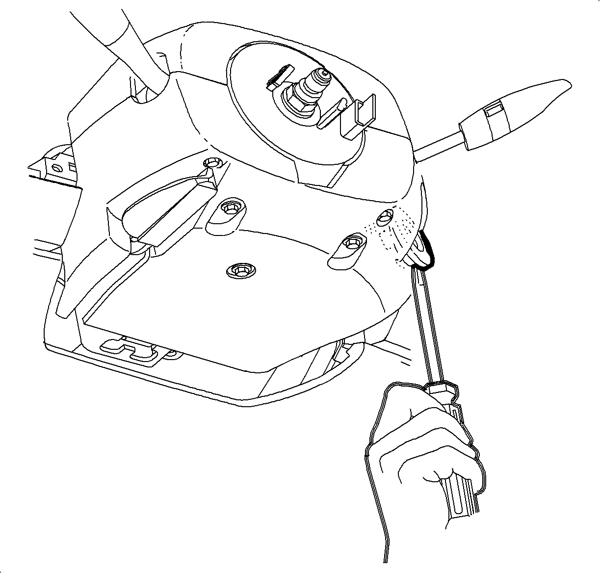
- Gently pry the edges of the ignition lock bezel with a blunt tool and separate it from the lower shroud.
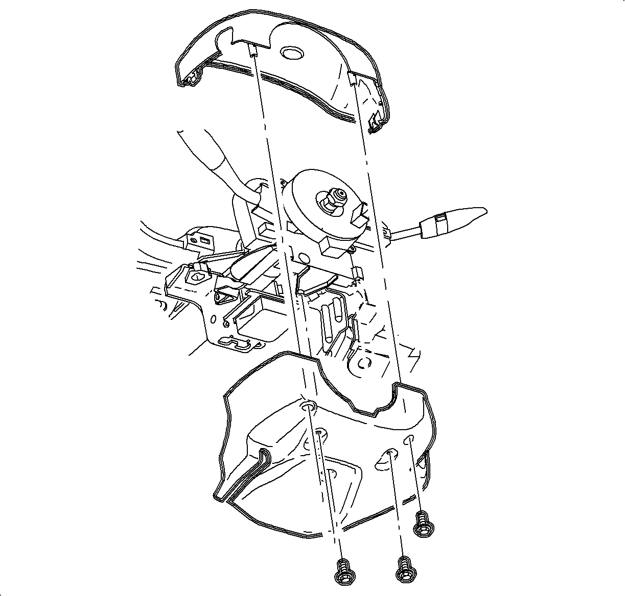
- Remove the upper and lower steering column shrouds and fasteners.
- Lower the steering column by pushing down on the steering column adjusting handle.
- Remove the I/P bezel:
- Remove the radio:
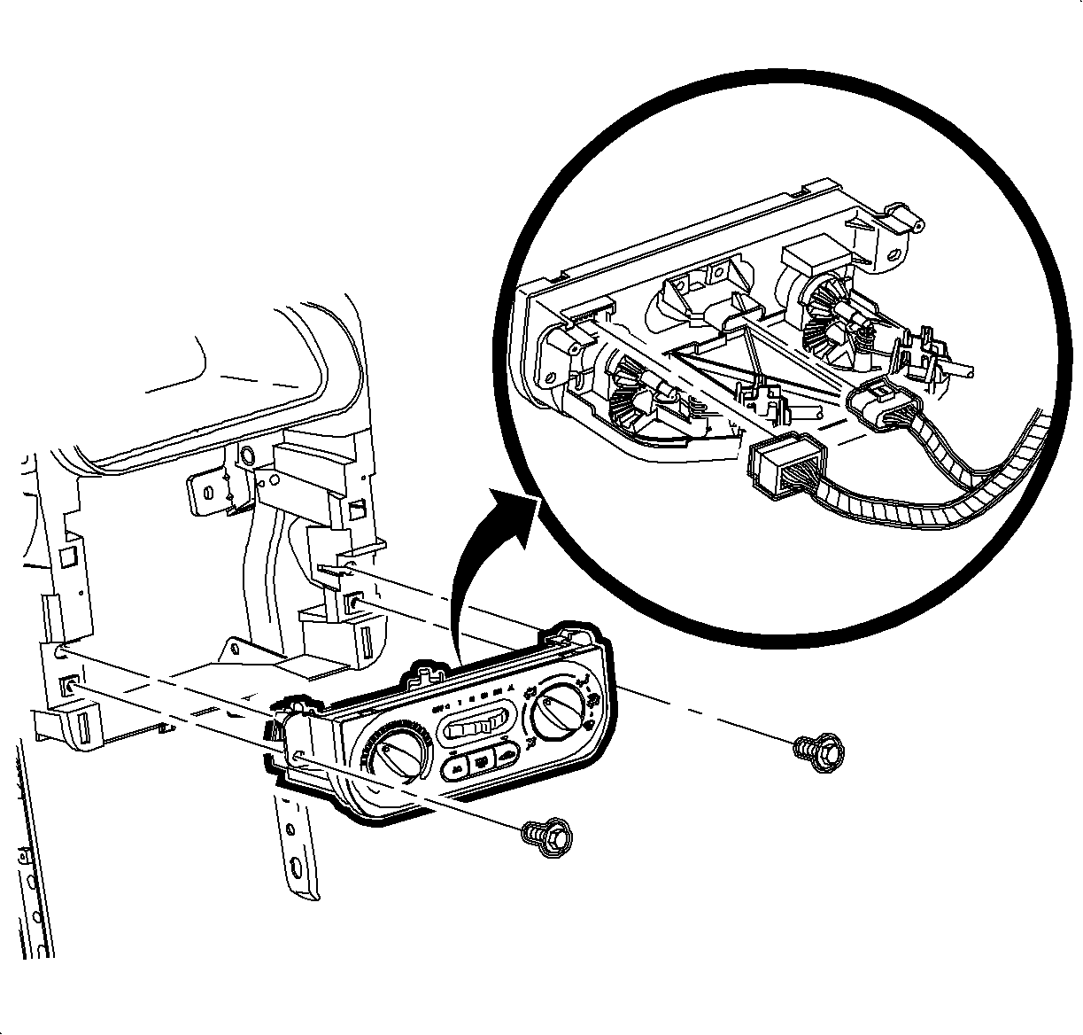
- Remove the HVAC controller:
- Remove the screws.
- Disconnect the HVAC blower switch connector.
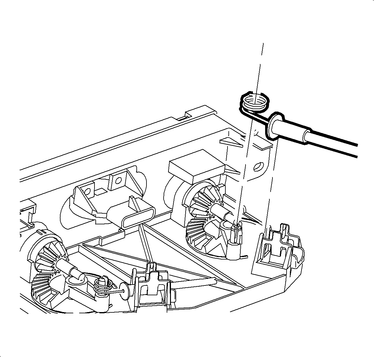
- Remove the temperature cable by squeezing the lock tabs together while pulling the cable, coiled end, straight up beyond the retaining tabs.
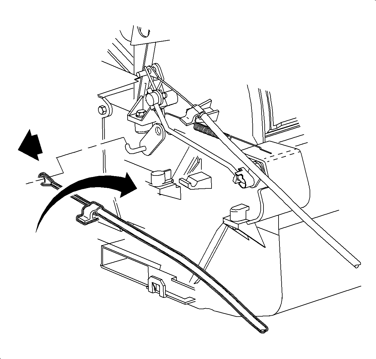
- Reach under the dash and release the temperature cable hold down clip by carefully pushing up on the plastic tab while pushing down on top of the cable.
- Slide the cable off of the temperature door hook.
- Remove the temperature cable. Service linkage shown in illustration.
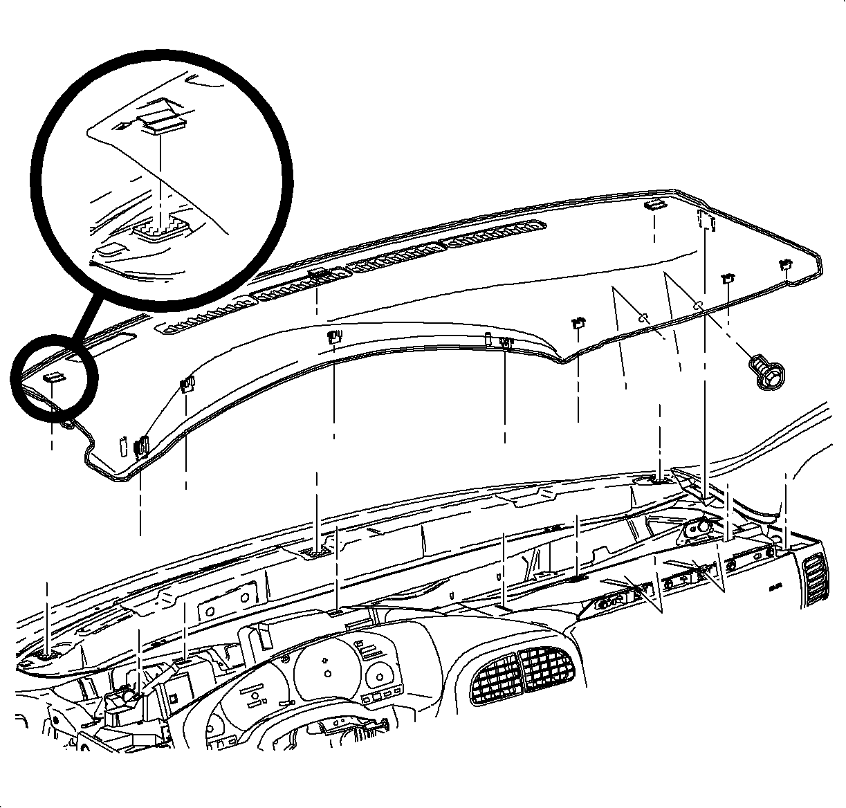
| 1.1. | Remove the screws located under the upper trim panel on the passenger's side of the vehicle. |
| Notice: Be careful not to damage the VIN plate when removing or replacing the upper trim panel. |
| 1.2. | Disengage the clips at the locations by grasping the edges of the upper trim panel and lifting up. |
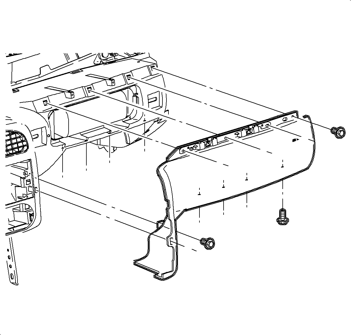
Notice: Do not remove weatherstrips. Adhesion will be lost if removed.
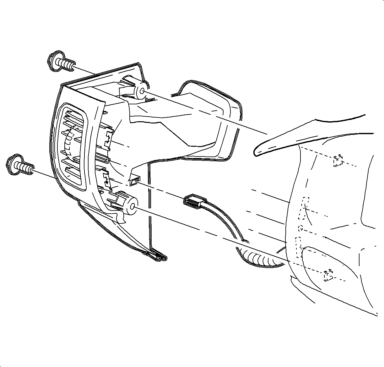
| 3.1. | Remove the screws. |
| 3.2. | Carefully disengage the clips at the instrument panel (I/P) retainer assembly locations. Use of a blunt tool will aid in disengaging the clips. |
| 3.3. | Maneuver the assemblies past the inner I/P retainer assembly and the weatherstrips. |
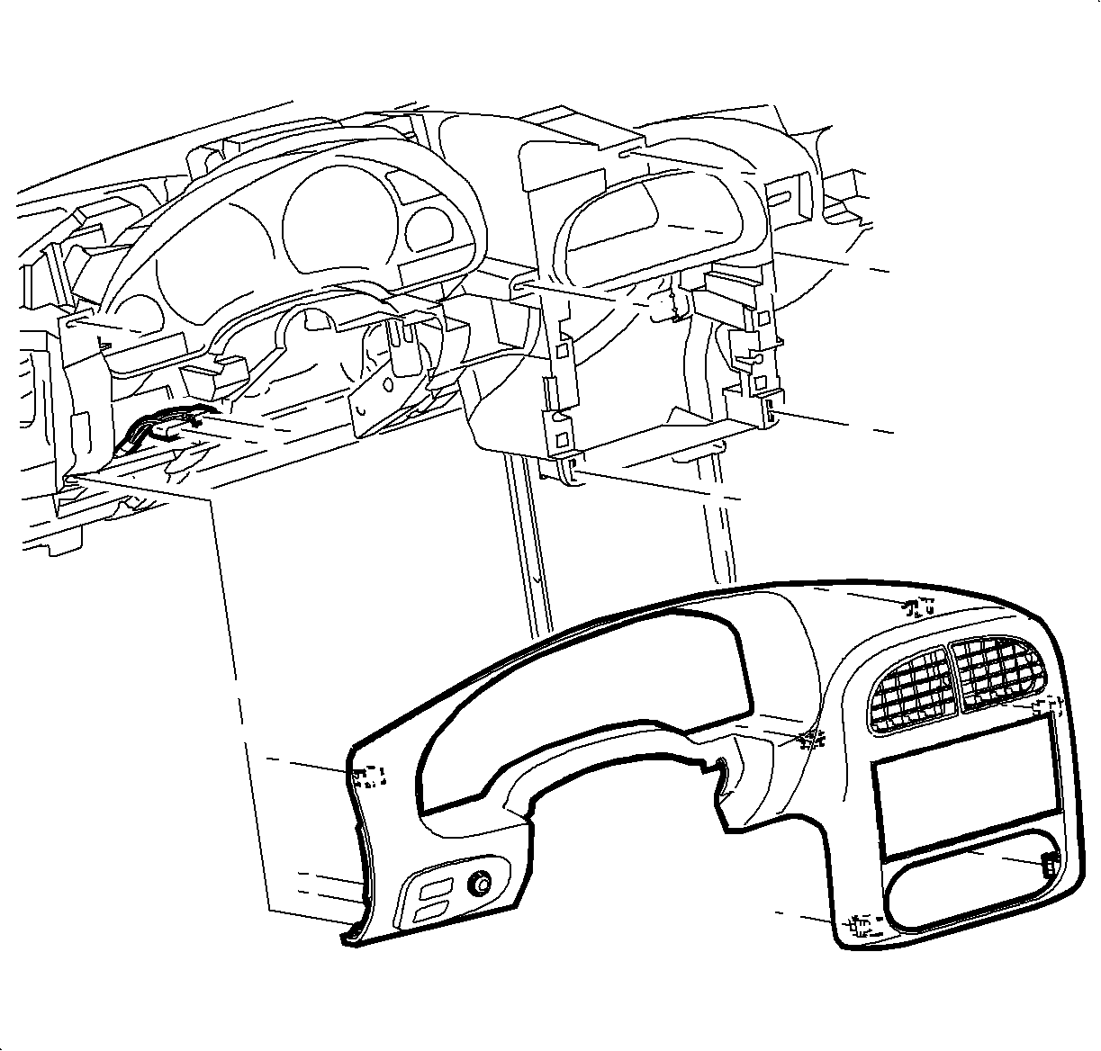
| 7.1. | Disengage the clips from the retainer assembly by grasping the edges of bezel near the clip location and pull outward. |
| 7.2. | Depress the wiring harness connector tabs and remove the harnesses from the dimmer/traction control switch assembly. |
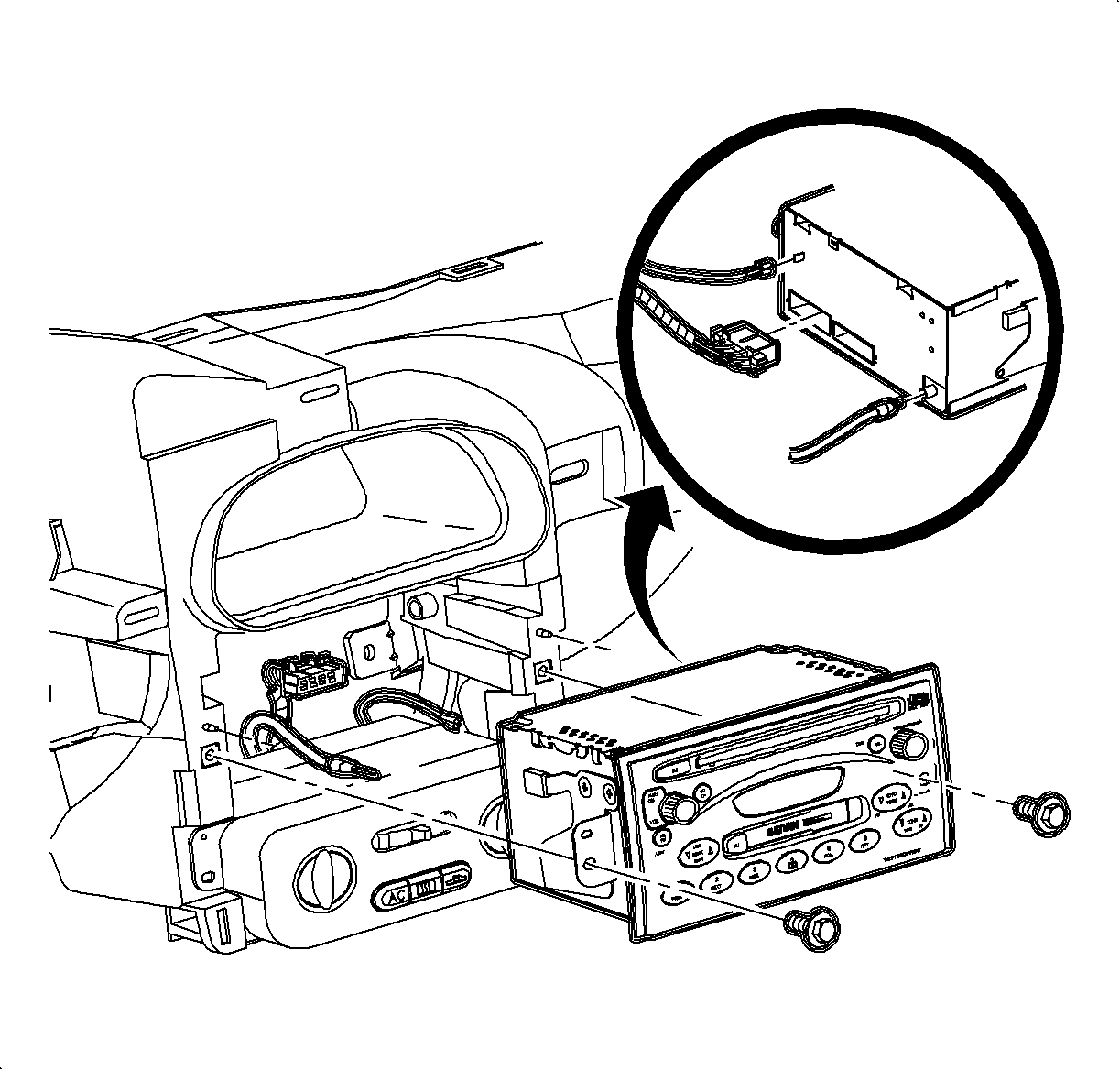
| 8.1. | Remove the radio screws. |
| 8.2. | Pull the radio out slightly to access the rear of radio. |
| 8.3. | Disconnect the electrical connector, antenna, and ground strap connector. |
Installation Procedure
- Install the temperature cable over the temperature door hook.
- Snap the temperature cable hold down clip over the temperature cable holder.
- Install the HVAC controller:
- Install the temperature valve cable onto the temperature valve pin.
- Snap the slot on the cable into the HVAC controller base.
- Install the blower switch connector.
- Install the screws.
- Install the radio:
- Install the I/P cluster bezel:
- Position the steering column upper shroud.
- Position the steering column lower shroud and install the screws.
- Install the ignition bezel:
- Install the left endcap assembly:
- Install the steering column filler panel screws.
- Install the I/P upper trim panel:
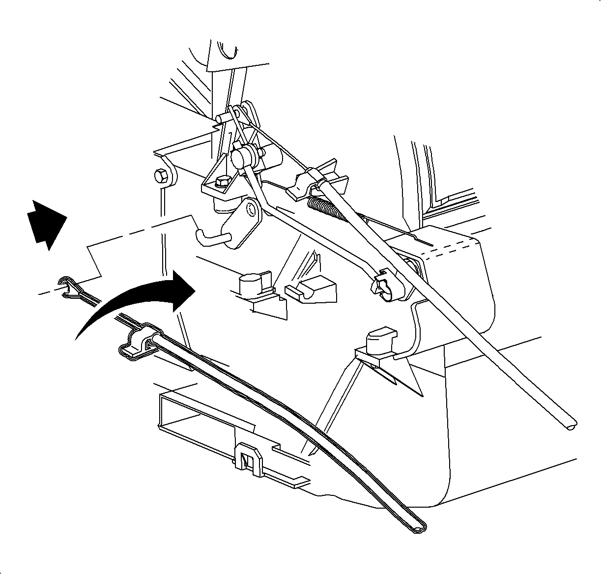
Cable Identification:
| • | Temperature Cable - White |
| • | Mode Cable - Black |

Important: Ensure that the wiring harnesses do not interfere with control lever movement.

Tighten
Tighten the HVAC controller-to-I/P retainer 2.5 N·m (22 lb in).

| 8.1. | Connect the wiring harnesses. |
| 8.2. | Connect the ground strap. |
| 8.3. | Connect the antenna lead. |
| 8.4. | Install the screws. |
Tighten
Tighten the radio-to-I/P retainer 2.5 N·m (22 lb in).

| 9.1. | Connect the dimmer/traction control switch wiring harnesses. |
| 9.2. | Position the I/P cluster bezel by lining up the clip location. |
| 9.3. | Snap the I/P cluster bezel in place by pushing at the clip locations. |

Tighten
Tighten the steering column shroud fasteners 1.5 N·m (13 lb in).

| 12.1. | Align the peg of the ignition bezel with the cut-out in the lower shroud. |
| 12.2. | Snap it into place. |

Important: Ensure that the endcap bottom portion is inside of the filler panel assembly.
| 13.1. | Maneuver the assembly past the inner I/P retainer assembly and the weatherstrips. |
| 13.2. | Snap the clips into I/P retainer assembly locations. |
| 13.3. | Install the screws. |
Tighten
Tighten the I/P endcap retaining screws 2.5 N·m (22 lb in).
Tighten
Tighten the steering column filler panel fasteners 2.5 N·m (22 lb in).
Notice: Be careful not to damage the VIN plate when removing or replacing the upper trim panel.
Important: Ensure that the upper trim panel seal is correctly seated on the forward edge before installing the upper trim panel.
| 15.1. | Ensure that the hook-and-loop fasteners on your trim panel are correctly inserted. |
| 15.2. | Position the upper trim panel on the retainer assembly. |
| 15.3. | Align the tabs on the sides of the upper trim panel with the openings in the windshield garnish molding. |
| 15.4. | Align the clips and the clip location. |
| 15.5. | Firmly snap in the clips at the clip locations. |
| 15.6. | Install the screws on the underside of the upper trim panel on the passenger's side of the vehicle. |
Tighten
Tighten the I/P upper trim panel fastener 6 N·m (53 lb in).
Temperature Control Cable Replacement RHD Domestic Only
Removal Procedure
- Loosen the upper trim panel:
- Loosen the steering column filler panel screws.
- Remove the right endcap assembly.
- Gently pry the edges of the ignition lock bezel with a blunt tool and separate it from the lower shroud.
- Remove the upper and lower steering column shrouds and fasteners.
- Lower the steering column by pushing down on the steering column adjusting handle.
- Lift and remove the upper shroud from the steering column.
- Remove the I/P bezel:
- Remove the I/P compartment.
- Remove the radio:
- Remove the HVAC controller:
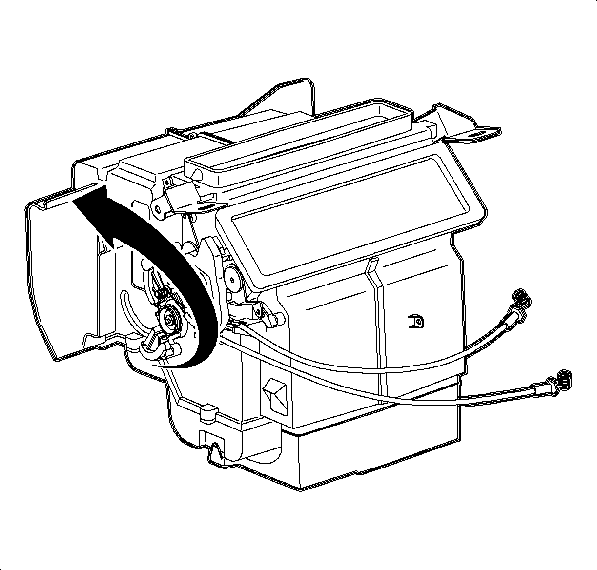
- Rotate the temperature cam fully counterclockwise.
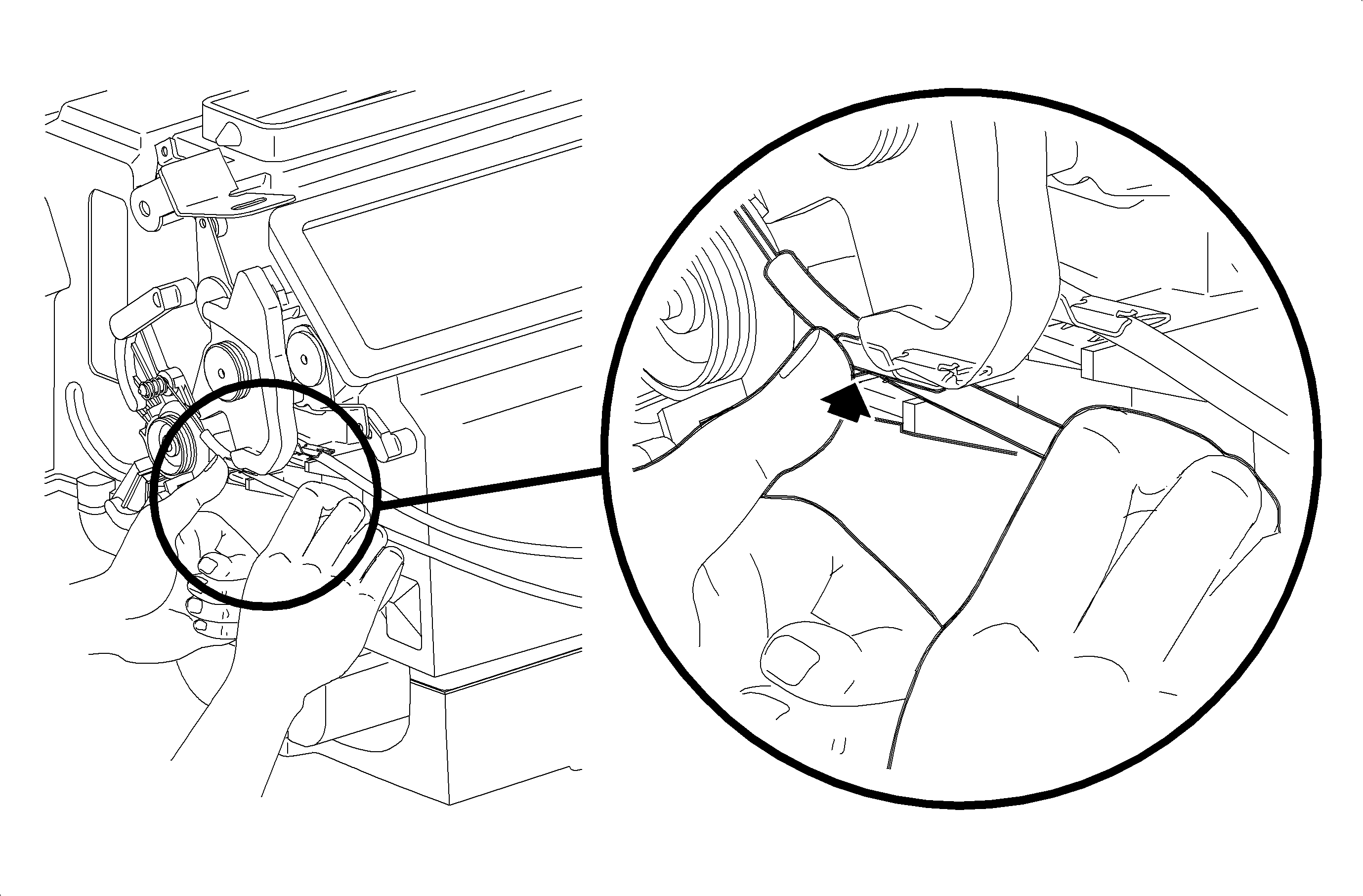
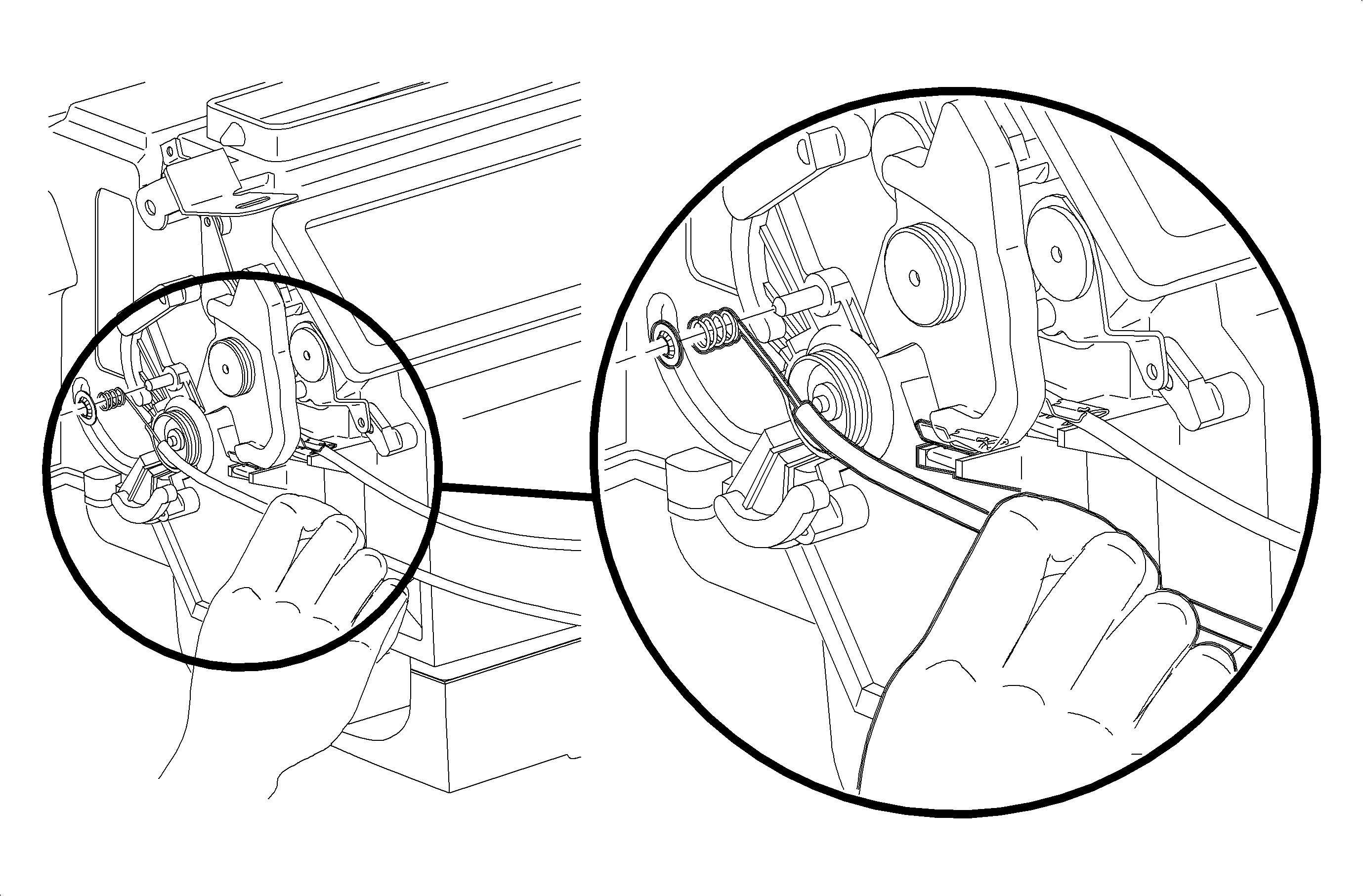
- Remove the temperature cable housing from the retainer clip by pressing upward on the upper tab of the clip while gently pulling outward on the cable housing.
- Remove the temperature cable circular push-on retainer from the temperature cam pin.
- Remove temperature cable.
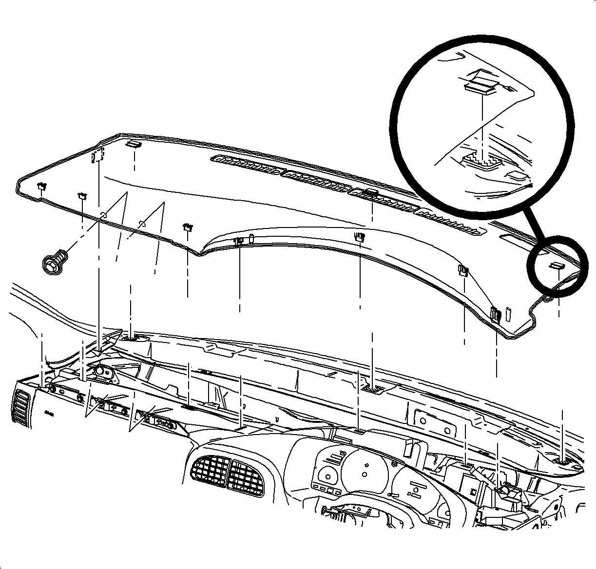
| 1.1. | Remove the screws located under the upper trim panel on the passenger's side of the vehicle. |
| Notice: Be careful not to damage the VIN plate when removing or replacing the upper trim panel. |
| 1.2. | Disengage the clips at the locations by grasping the edges of the upper trim panel and lifting up. |
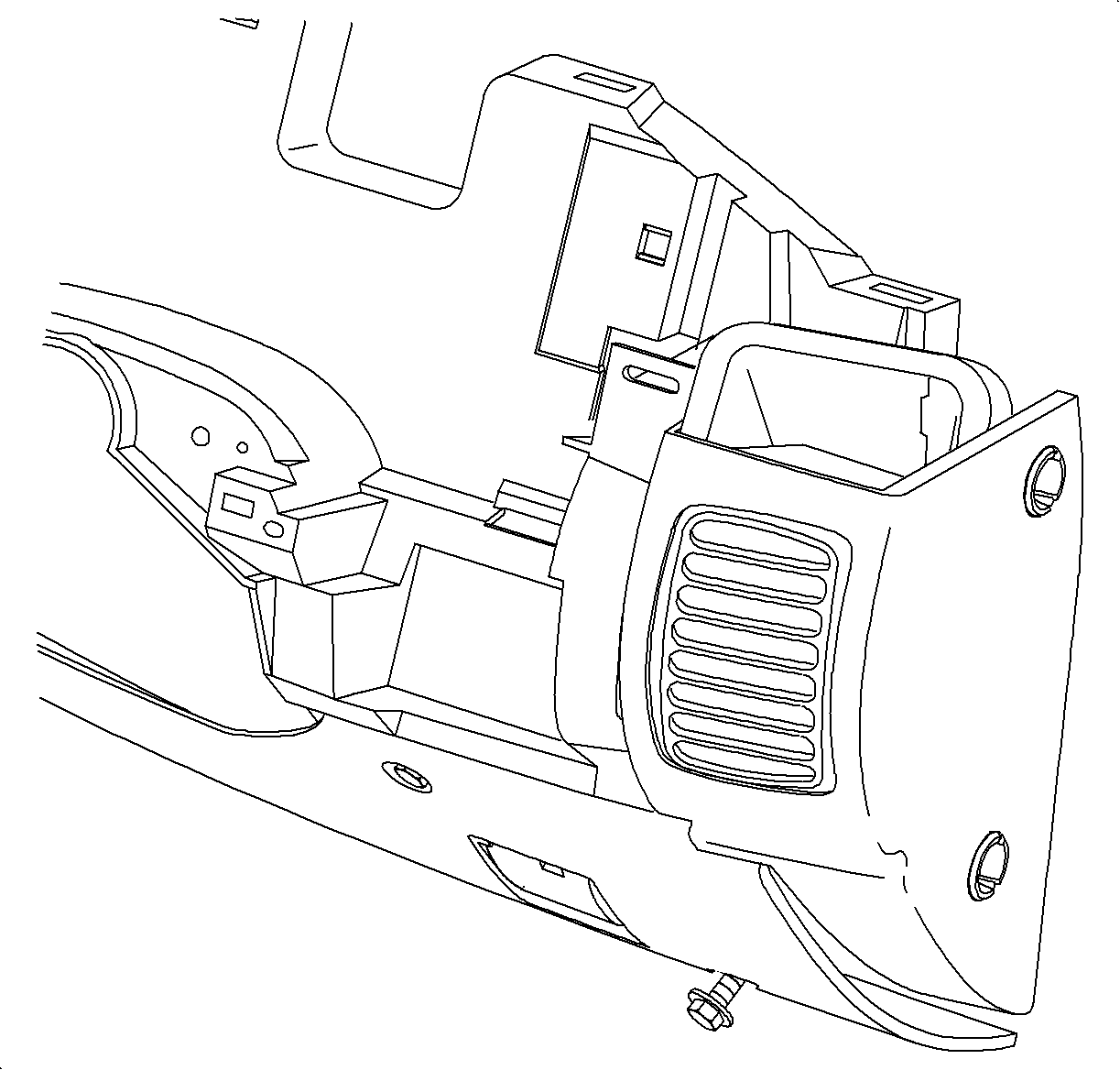
Notice: Do not remove weatherstrips. Adhesion will be lost if removed.
| 3.1. | Remove the screws. |
| 3.2. | Carefully disengage the clips at the instrument panel (I/P) retainer assembly locations. Use of a blunt tool will aid in disengaging the clips. |
| 3.3. | Maneuver the assemblies past the inner I/P retainer assembly and the weatherstrips. |


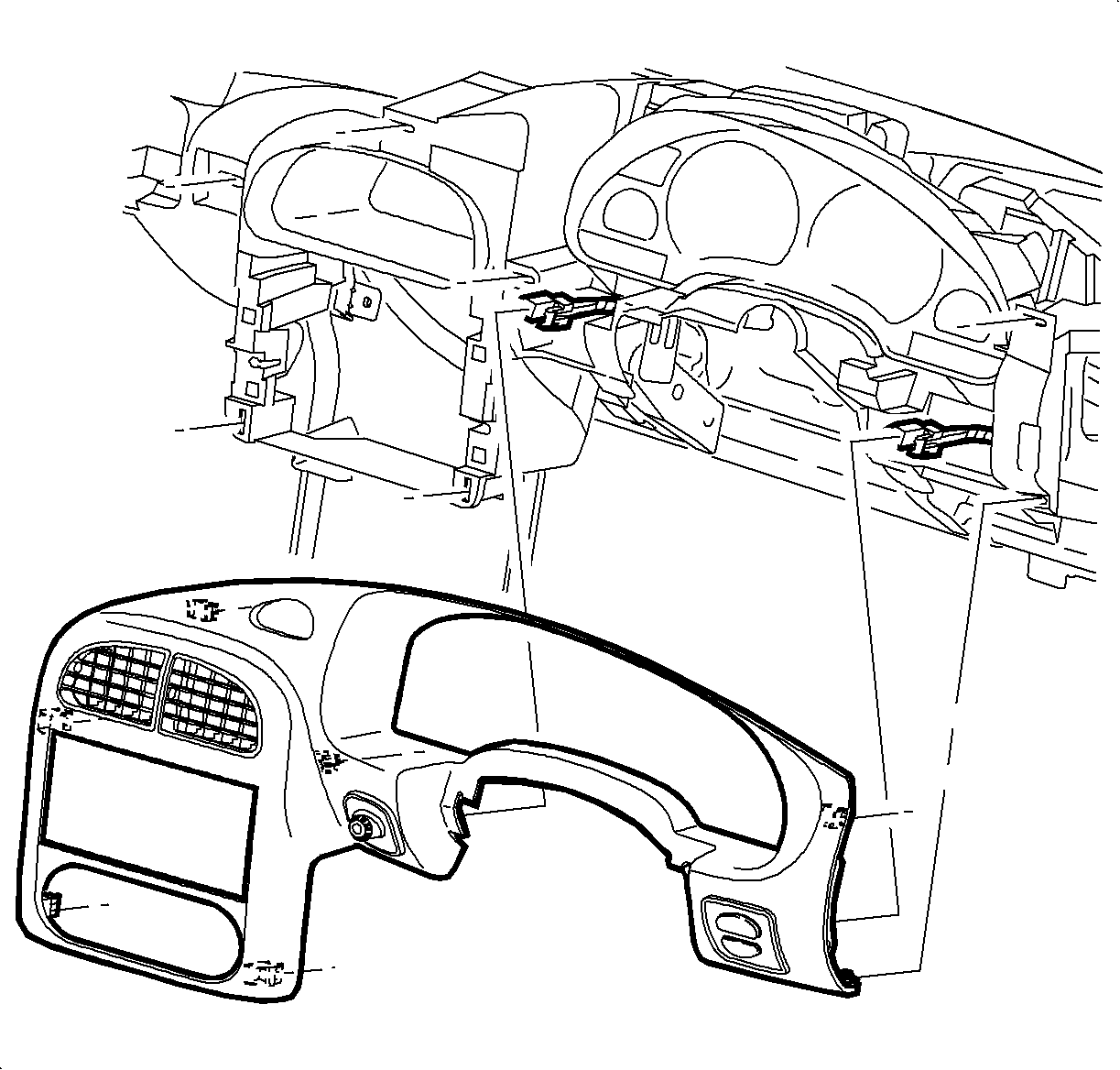
| 8.1. | Disengage the clips from the retainer assembly by grasping the edges of the bezel near the clip location and pull outward. |
| 8.2. | Depress the wiring harness connector tabs and remove the harnesses from the dimmer/traction control switch assembly. |
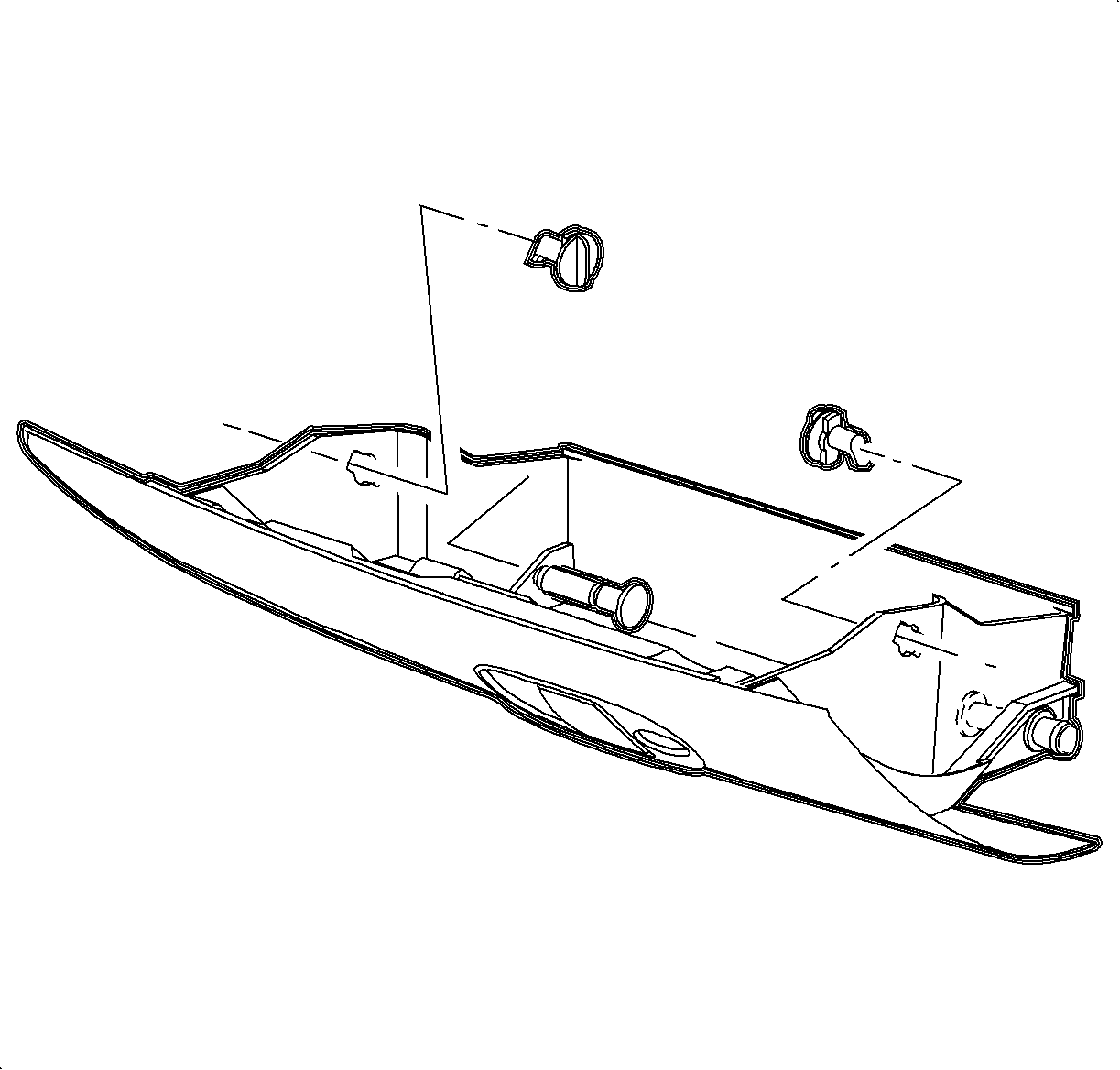
| 9.1. | Open the I/P compartment door. |
| 9.2. | Turn the right and left I/P compartment door stop assemblies to release the door and compartment assembly from the I/P retainer assembly. |
| Important: Lower the I/P door pins are on the right and left outside edges at base of the compartment. |
| 9.3. | Push the lower I/P door pins from the outside of the door to the inside I/P compartment. |

| 10.1. | Remove the radio screws. |
| 10.2. | Pull the radio out slightly to access rear of the radio. |
| 10.3. | Disconnect the electrical connector, antenna, and ground strap connector. |

| 11.1. | Remove the screws. |
| 11.2. | Disconnect the HVAC blower switch connector. |

| 11.3. | Remove the temperature cable by squeezing the lock tabs together while pulling the cable, coiled end, straight up beyond the retaining tabs. |
Installation and Adjustment Procedure
- Rotate the temperature cam fully counterclockwise.
- Install the temperature cable on the temperature cam pin and install the circular push-on retainer.
- Install the temperature cable over the HVAC control pin.
- Install the temperature cable housing into the channel and push down to lock it into place.
- Place the HVAC control temperature knob completely to the right - full hot.
- Verify that the temperature cam is still in a full counterclockwise position.
- Press the temperature cable housing firmly into the retainer clip to lock.
- Move the HVAC control temperature knob from hot to cold to verify proper installation.
- Install the HVAC Controller.
- Install the radio:
- Install the I/P compartment.
- Install the I/P cluster bezel:
- Position the upper steering column shroud.
- Position the lower steering column shroud and install the screws.
- Install the ignition bezel.
- Install the right endcap assembly:
- Install the steering column filler panel screws.
- Install the I/P upper trim panel:

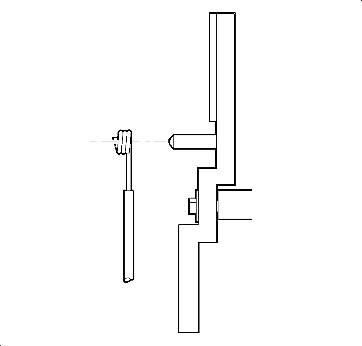
Important: Install the temperature cable with the wire eyelet wrap as shown.

Important: Do not install the temperature cable housing into the retainer clip at this time.

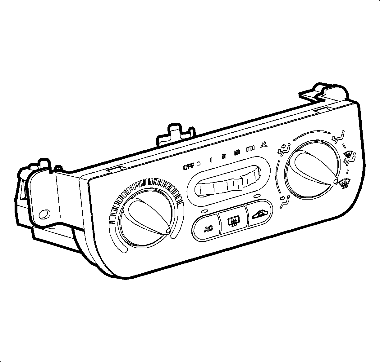


Important: Ensure wiring that the harnesses do not interfere with control lever movement.
| 9.1. | Install the blower switch connector. |
| 9.2. | Install the screws. |
Tighten
Tighten the HVAC controller-to-I/P retainer 2.5 N·m (22 lb in).

| 10.1. | Connect the wiring harnesses. |
| 10.2. | Connect the ground strap. |
| 10.3. | Connect the antenna lead. |
| 10.4. | Install the screws. |
Tighten
Tighten the radio-to-I/P retainer 2.5 N·m (22 lb in).

| 11.1. | Position the I/P compartment door assembly to the retainer assembly. |
| 11.2. | Install the I/P compartment door pins into the instrument panel retainer assembly. |
| 11.3. | Lift the I/P compartment enough to install the I/P compartment door stop assemblies. |
| 11.4. | Close the I/P compartment door. |

| 12.1. | Connect the dimmer/traction control switch wiring harnesses. |
| 12.2. | Position the I/P cluster bezel by lining up the clip location. |
| 12.3. | Snap the I/P cluster bezel in place by pushing at the clip locations. |

Tighten
Tighten the steering column shroud fasteners 1.5 N·m (13 lb in).

| 15.1. | Align the peg of the ignition bezel with the cut-out in the lower shroud. |
| 15.2. | Snap it into place. |
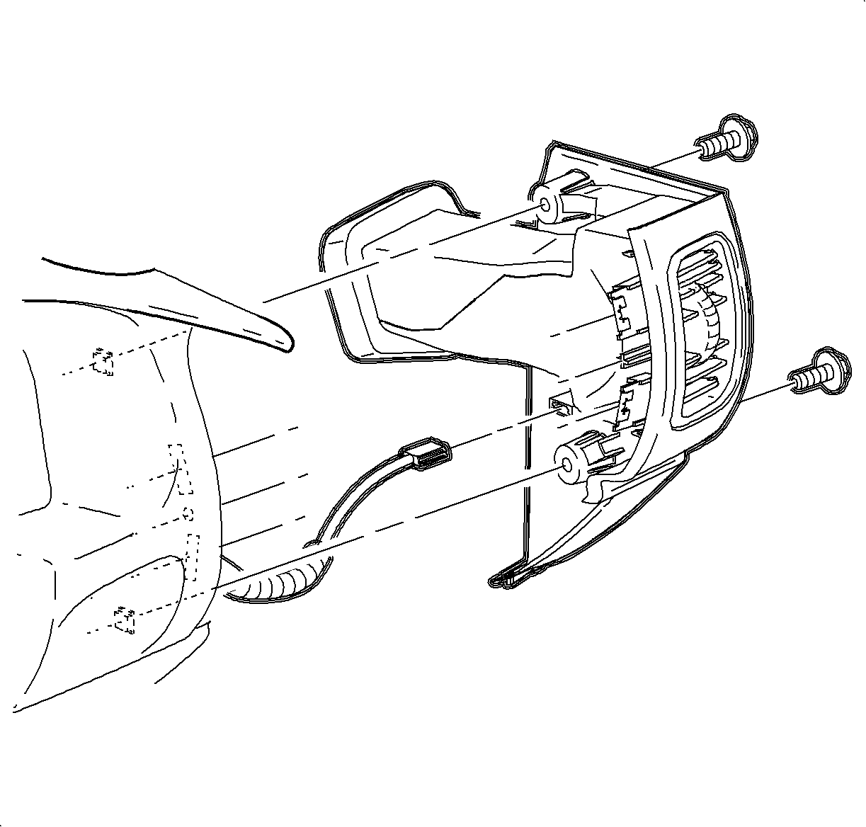
Important: Ensure that the endcap bottom portion is inside of the filler panel assembly.
| 16.1. | Maneuver the assembly past the inner I/P retainer assembly and the weatherstrips. |
| 16.2. | Snap the clips into the I/P retainer assembly locations. |
| 16.3. | Install the screws. |
Tighten
Tighten the I/P endcap retaining screws 2.5 N·m (22 lb in).

Tighten
Tighten the steering column filler panel fasteners 2.2 N·m (20 lb in).
Notice: Be careful not to damage the VIN plate when removing or replacing the upper trim panel.

Important: Ensure upper trim panel seal is correctly seated on forward edge before installing upper trim panel.
| 18.1. | Ensure that the hook-and-loop fasteners on the upper trim panel are correctly inserted. |
| 18.2. | Position the upper trim panel on the retainer assembly. |
| 18.3. | Align the tabs on the sides of the upper trim panel with the openings in the windshield garnish molding. |
| 18.4. | Align the clips and the clip location. |
| 18.5. | Firmly snap in the clips at the clip locations. |
| 18.6. | Install the screws on the underside of the upper trim panel on the passenger's side of the vehicle. |
Tighten
Tighten the I/P upper trim panel fastener 6 N·m (53 lb in).
