Air Conditioning/Recirc
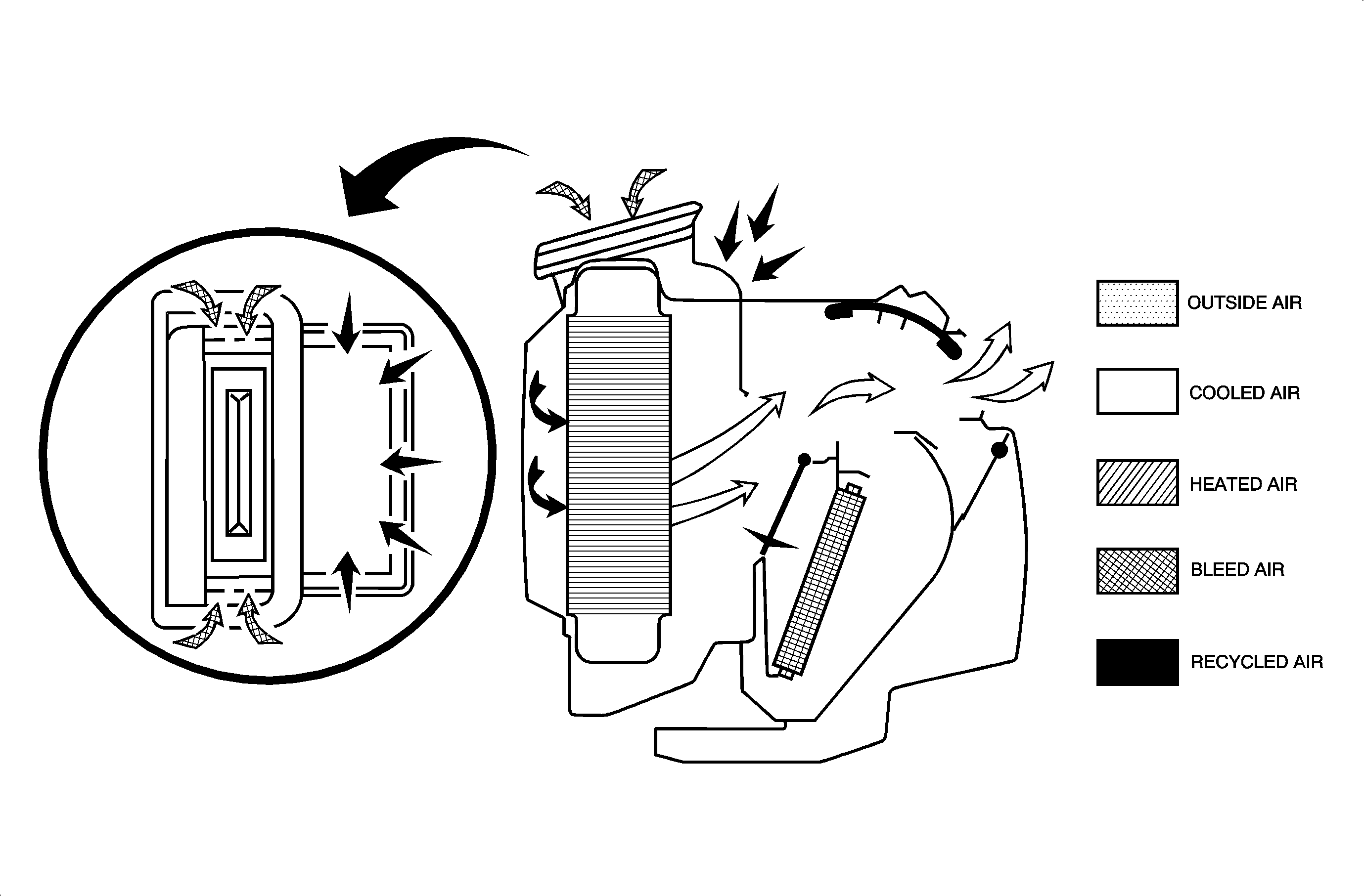
The air conditioning compressor may be energized in any mode by depressing the A/C switch. This will cause the air passing through the evaporator core to be cooled and dehumidified.
When the Recirc button is depressed, the Recirc motor moves the air inlet valve from outside air to recirculate air position. In this position, air from the passenger compartment is recirculated through the module. This function allows for maximum air conditioning performance. The use of Recirc in cold and damp or humid weather will cause the windows to fog up.
When defroster/defog is selected, the controller will return the HVAC module operation to the mode that draws fresh outside air into the vehicle regardless of the position of the Recirc button.
Bi-Level
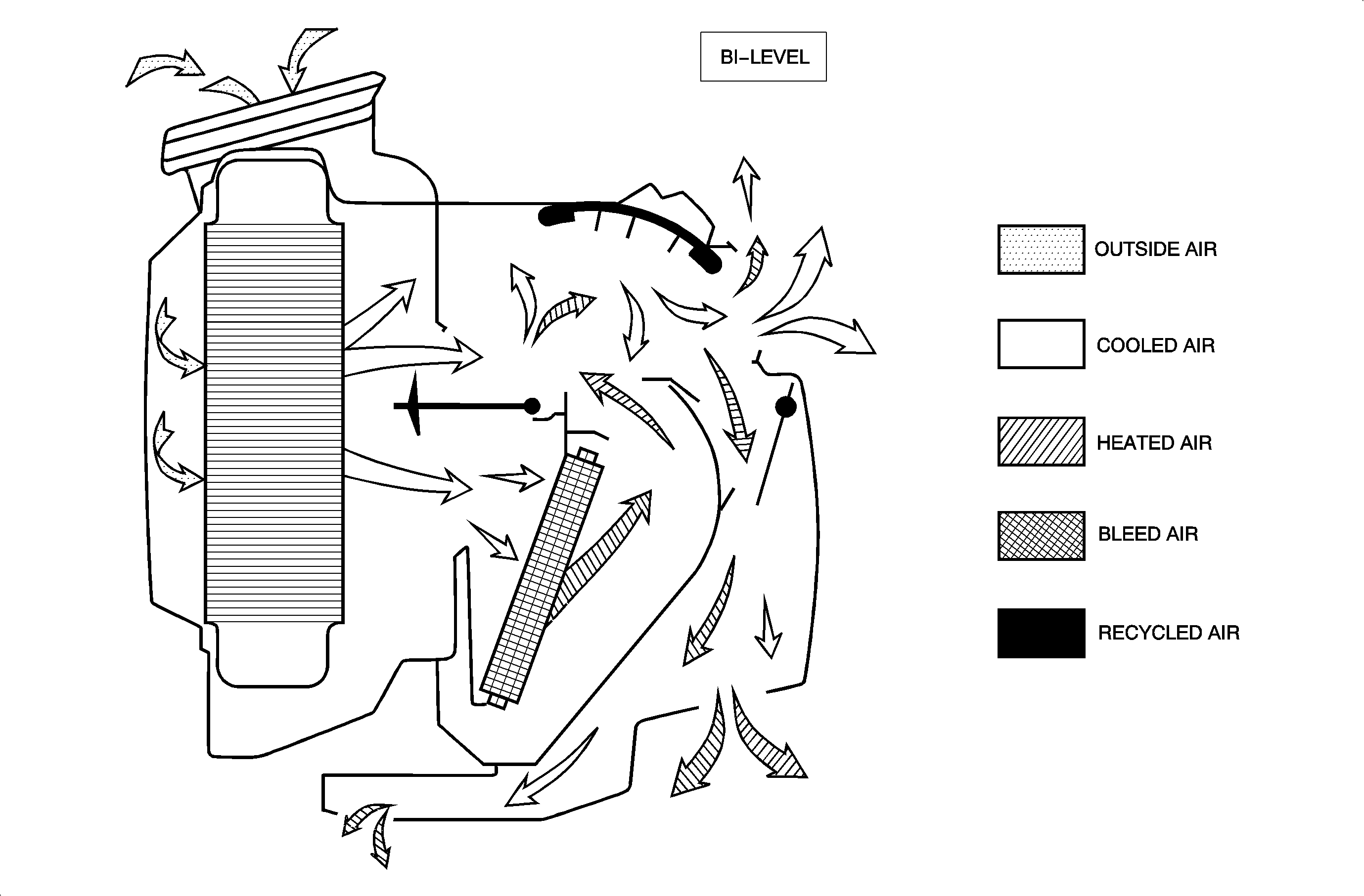
When Bi-Level mode is selected, air enters the module and passes through the evaporator core. Depending on the temperature knob position, some air may pass through the heater core. This air will mix with the cooler air and then be discharged through the instrument panel and heater outlets.
Air flow design characteristics of the module will divert most of this tempered air out of the instrument panel outlets, with the air from the heater outlet being slightly warmer.
Vent Mode
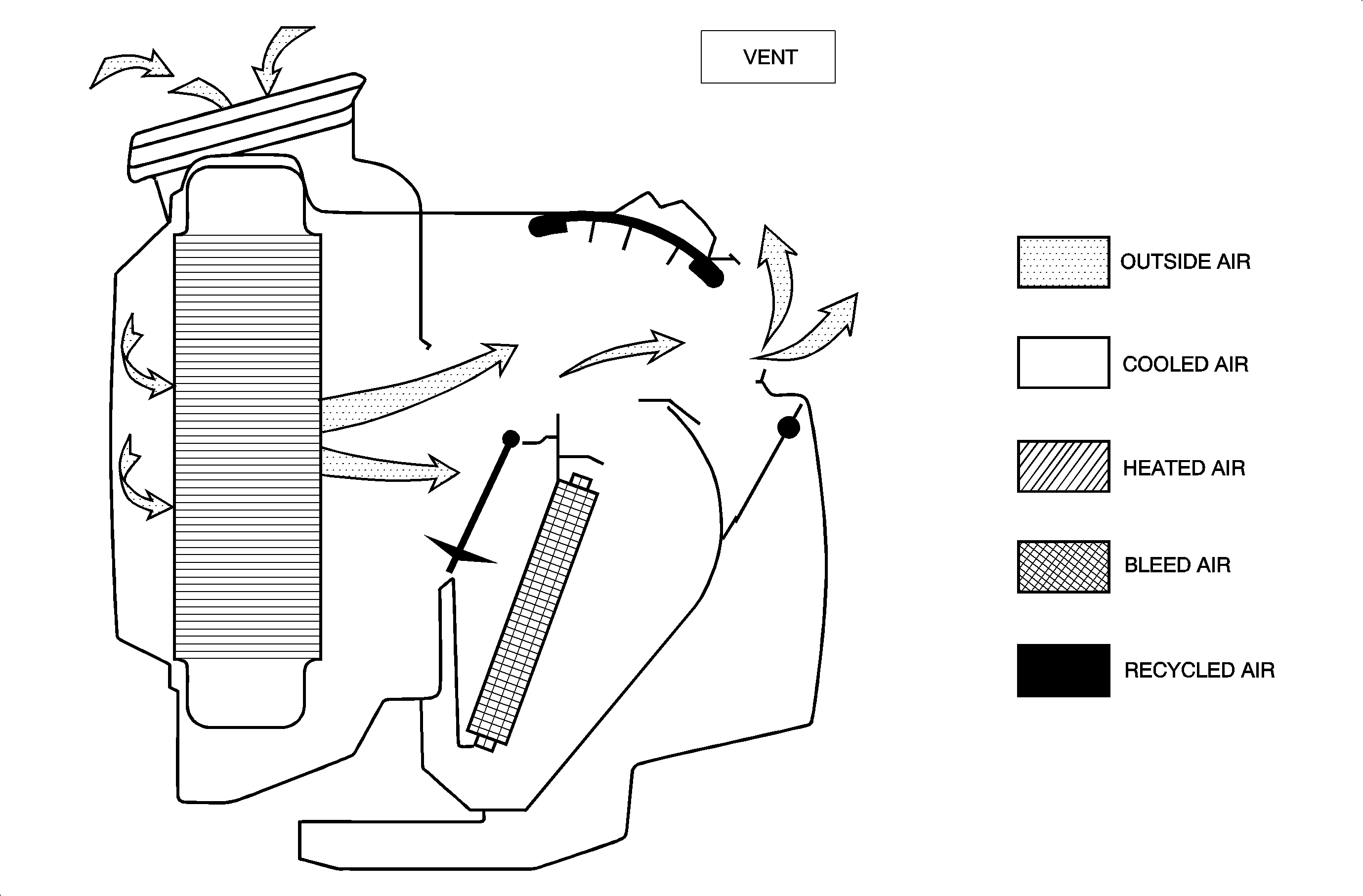
When Vent mode is selected, air enters the module and flows through the evaporator. The air then passes through the mode valve and out through the instrument panel outlets.
The air may be warmed by directing some or all to pass through the heater core by adjusting the temperature knob to the desired heat level.
Heater Mode
Important: During extremely cold weather, -12°C (10°F) or colder, the engine's coolant temperature will decrease quickly when idling with the heater fan on high speed and cool air may flow from the heater outlets. The fan control switch should be set at a slower speed position (fan speed I or II) to maintain the hottest air flow.
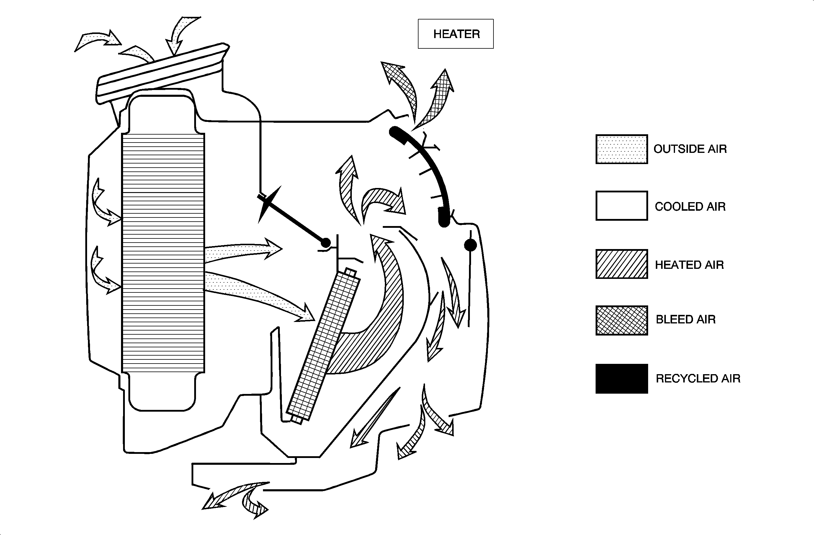
When Heater mode is selected, with Recirc OFF, outside air enters the module and passes through the evaporator core. With A/C button OFF, the air is no cooler or drier than when it entered. When the temperature knob is moved from cold to hot, the temperature valve directs some or all of the air from the evaporator through the heater core, warming the air passing through it. The mode valve closes and directs most of the warmed air to the lower and rear air outlets. A small amount of bleed air exits through the defroster ducts.
Defrost Mode
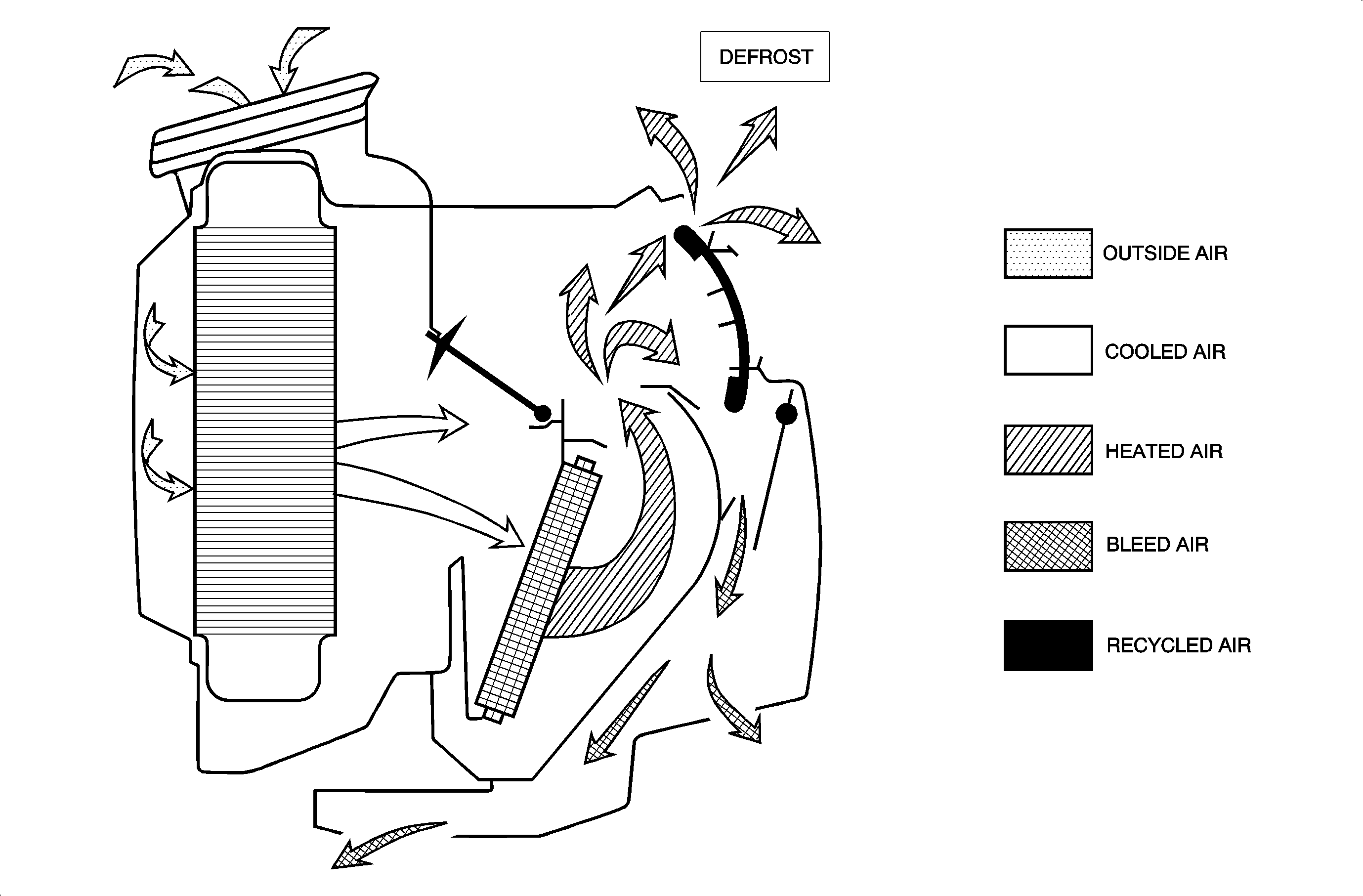
Important: Defrost/Defogging Windows: This setting directs the air through the windshield defroster outlets onto the windshield and past the front side windows. Use this setting if windows are fogged or icy. This setting will also help defog the front side window. Set the control knob to defrost and set the temperature to full hot (far to the right). To quickly clear the windows, put the fan control switch to high and push the A/C button. (An indicator light will go ON.)
Important: To keep the glass fog free, the mode select knob should be positioned between Heater and Defrost. The Recirc button should be left OFF. The mode knob should be used to regulate air flow depending on driving conditions.
When the Defrost mode is selected, outside air enters the module and passes through the evaporator core. The air then passes through the heater core where it is heated. For maximum defrosting, or in high humidity conditions, do not engage the Recirc button. After the air passes through the heater core, most of the air is directed through the mode valve to the defroster outlet. A small amount of bleed air will pass by the mode valve and out the lower air outlet. The figure shows air flow with the temperature knob set to full hot.
Compressor
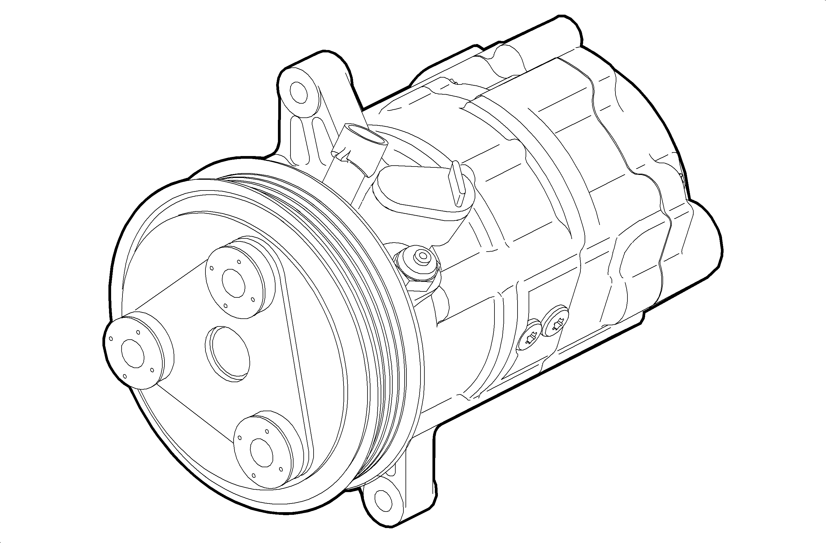
The Saturn compressor is a variable displacement rotary vane type pump. The rotor assembly houses five lightweight vanes that extend outward contacting the cylinder wall creating the compression area. The compressor has an internal control valve that allows it to change its pumping capacity or displacement, reacting to heat loads on the air conditioning system. The range of displacement can vary from 5 percent (5.5 cc) to 100 percent (110 cc). The compressor's natural or resting state is at minimum displacement.
The compressor performs two main functions. It compresses the low pressure refrigerant vapor from the evaporator into a high pressure high temperature vapor, and pumps compressor oil through the A/C system.
Compressor Clutch
The electromagnetic clutch engages the compressor when the A/C button is depressed. The clutch consists of a drive plate, pulley, and a coil assembly. The drive plated is bolted to the compressor shaft. The pulley and bearing assembly is press fitted onto the compressor hub, and the coil assembly is screwed to the compressor body. When current flows through the coil assembly, the drive plate is pulled into the pulley by electromagnetic force.
When the coil assembly is not energized, the drive plate separates from the pulley and the compressor stops. A diode is used to protect electrical circuits from voltage spikes. The diode is located in the underhood fuse block.
A thermal link fuse is incorporated into the coil. If the temperature of the coil exceeds 214°C +/- 3°C (417°F +/- 37°F), the link will melt creating an open coil circuit. When the coil is de-energized the drive plate releases the pulley and the compressor stops pumping. A typical coil resistance will measure 3.22 +/- 0.08 ohms at 22°C (72°F).
Pressure Relief Valve
Mounted in the front head is a high pressure relief valve. To protect the A/C system from high pressure in the event of an electrical control system failure, the valve will begin to open at about 3654 kPa (530 psi). As system pressure is reduced, the valve will reseat at about 2930 kPa (425 psi). If the valve ever opens it must be replaced.
A/C Compressor Control Logic
The body control module (BCM) receives an A/C request input when the A/C button on the HVAC control head is depressed with fan speed on. The A/C button circuit, however, is in series with the high/low A/C pressure switch circuit. Therefore, the correct refrigerant pressure range in the system must be present for the BCM to receive an A/C request. Once this request is received, the BCM will send the powertrain control module (PCM) the A/C request over the Class II link. When the PCM receives the request from the BCM, it will command a driver ON, which will pull the A/C relay coil circuit to ground. This will cause the relay to energize, allowing current to flow to the A/C compressor clutch and allow the A/C compressor to operate. The PCM can turn Off the A/C relay with the A/C request still ON under the following conditions:
| • | Engine coolant temperature (ECT) is greater than 118°C (244°F). A/C relay will be turned back ON when the ECT is less than 113°C (234°F) |
| • | Wide open throttle (WOT) acceleration for up to 15 seconds (WOT = TP angle greater than 95 percent). |
| • | The vehicle speed is less than 8 km/h (5 mph), intake air temperature (IAT) is greater than 66°C (151°F) and TP angle change is greater than 0.4 percent. A/C relay will be turned OFF for 0.4 seconds for auto trans or 2 seconds with manual trans. |
| • | The engine speed is greater than 6375 RPM. A/C relay will be turned back ON when engine speed is less than 4500 RPM for 2 seconds. |
| • | The IAT is between 7° and 25°C (45° and 77°F) and vehicle speed is present. The PCM will cycle the A/C clutch ON once every 60 seconds depending on IAT and vehicle speed. |
Important: The A/C compressor contains an internal high pressure switch that will open if the high side pressure exceeds the maximum amount the system can handle. If the A/C compressor is not running due to this condition or one that would cause the compressor not to run when the PCM thinks the A/C is ON, the learned idle air control (IAC) values will be affected. The PCM will relearn a new idle position based on no A/C engine load. If the A/C compressor condition terminates, the idle speed will be initially low until the PCM learns the new A/C engine load idle position.
The high/low pressure switch can turn the A/C request to the BCM OFF. If the high side pressure exceeds 2758 +1/- 138 kPa (400 +1/- 20 psi), the switch will open and will NOT close until the high side pressure drops below 1724 +1/-345 kPa (250 +1/- 50 psi). If the high side pressure drops below 276 kPa (40 psi), the switch will open. The switch will close when the pressure exceeds 276 kPa (40 psi).
Optional After Blow Body Control Logic
Important: The HVAC After blow function is not enabled from the factory. To enable function, refer to "Special Functions" accessed through the Tech 2.
The HVAC HI Blower Fan Output can be requested by either the HI Blower Switch Input or the HVAC After Blow Function. When requested by the HI blower switch the BCM receives the switch input and switches the blower relay to battery. This energizes the blower relay coil and turns the blower motor on High.
The HVAC After Blow function is used to eliminate the odor associated with A/C usage. The "After Blow" is a method whereby the HVAC blower is run for a few minutes, approximately 50 minutes after the vehicle is turned OFF, in order to physically blow off excess condensation and eliminate odors.
The PCM sends vehicle speed, air intake temperature (used for ambient temperature), and A/C clutch status to the BCM. When the BCM receives the above information from the PCM and determines the A/C has been engaged during the ignition cycle, the After Blow is requested to occur after vehicle power down.
Once the request for After Blow is made, the BCM monitors air intake temperature to determine the duration of the After Blow required. A sufficiently high ambient temperature, approximately 30°C (86°F) or higher, causes an After Blow event of approximately 3 minutes. A lower ambient temperature, below 30°C (86°F), allows for a shorter duration, approximately 32 seconds. The vehicle speed must have met or exceeded 48 km/h (30 mph) to cause an After Blow event when all other conditions have been met.
After vehicle power down, After Blow occurs after a delay. In the event that the ignition is cycled ON during the delay period or the After Blow event, the After Blow output is turned OFF.
Condenser - General Description
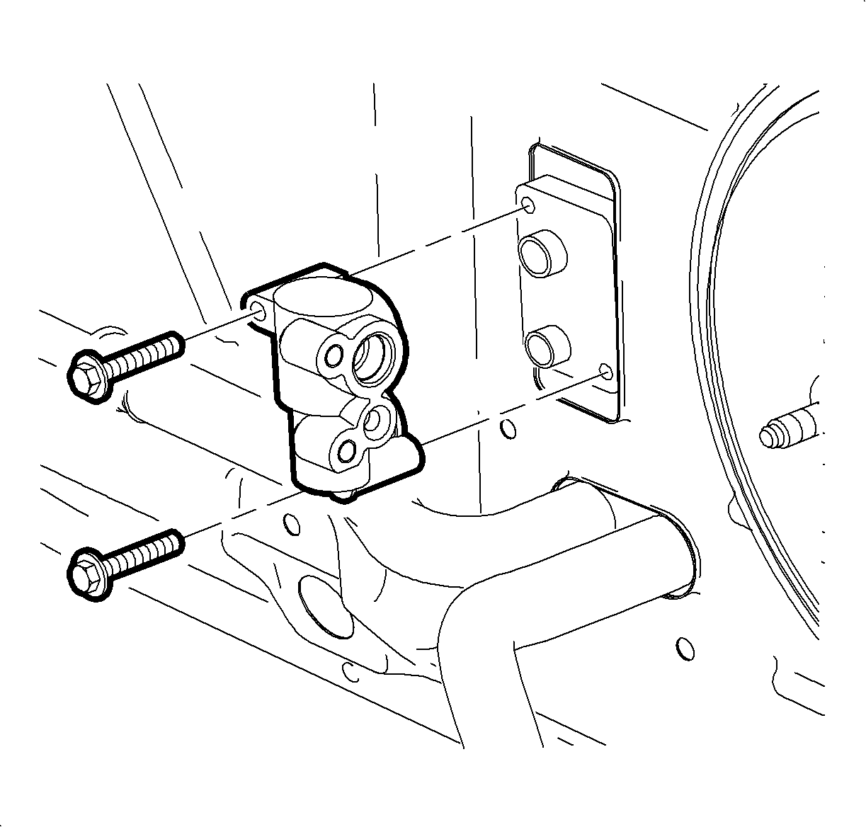
The condenser assembly in front of the radiator is made up of coils which carry refrigerant, and cooling fins to provide rapid transfer of heat. The air passing through the condenser cools the high pressure refrigerant vapor causing it to condense into a liquid.
The condenser is made of aluminum tubes on which are mounted aluminum fins.
The fins provide the cooling capacity of the condenser and should be kept clean and should not be bent or otherwise damaged.
Important: All models are serviced with the "header type" condenser.
Receiver/Dehydrator - General Description
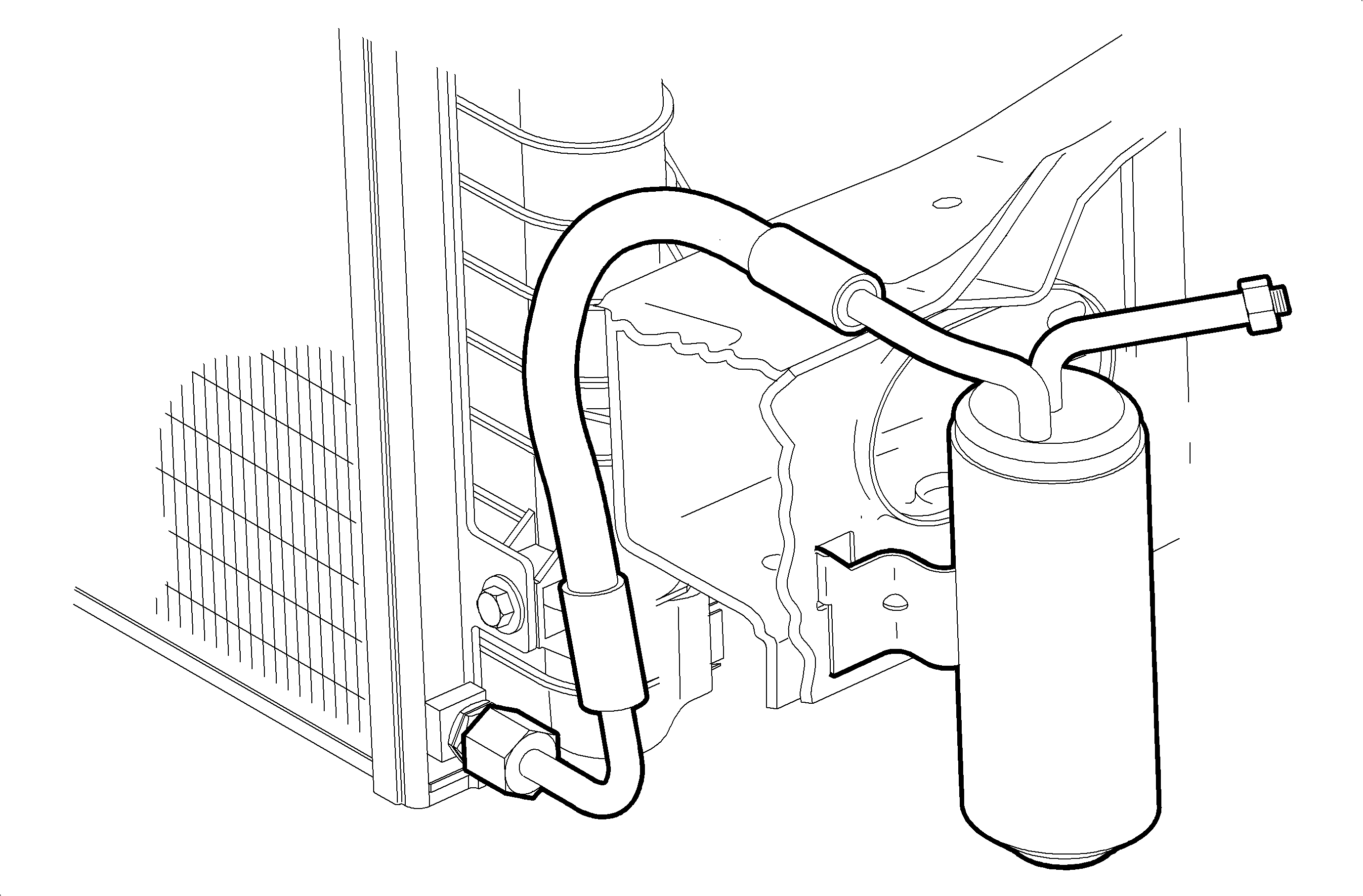
Connected to the condenser assembly outlet pipe, the sealed receiver-dehydrator assembly acts as a refrigerant storage container receiving R-134a liquid.
At the center of the receiver-dehydrator is the desiccant which acts as a drying agent for moisture that may have entered the system. The filter and baffle on the upper end of the component is for retaining the desiccant bags and removing contamination from the A/C system.
Thermal Expansion Valve - General Description
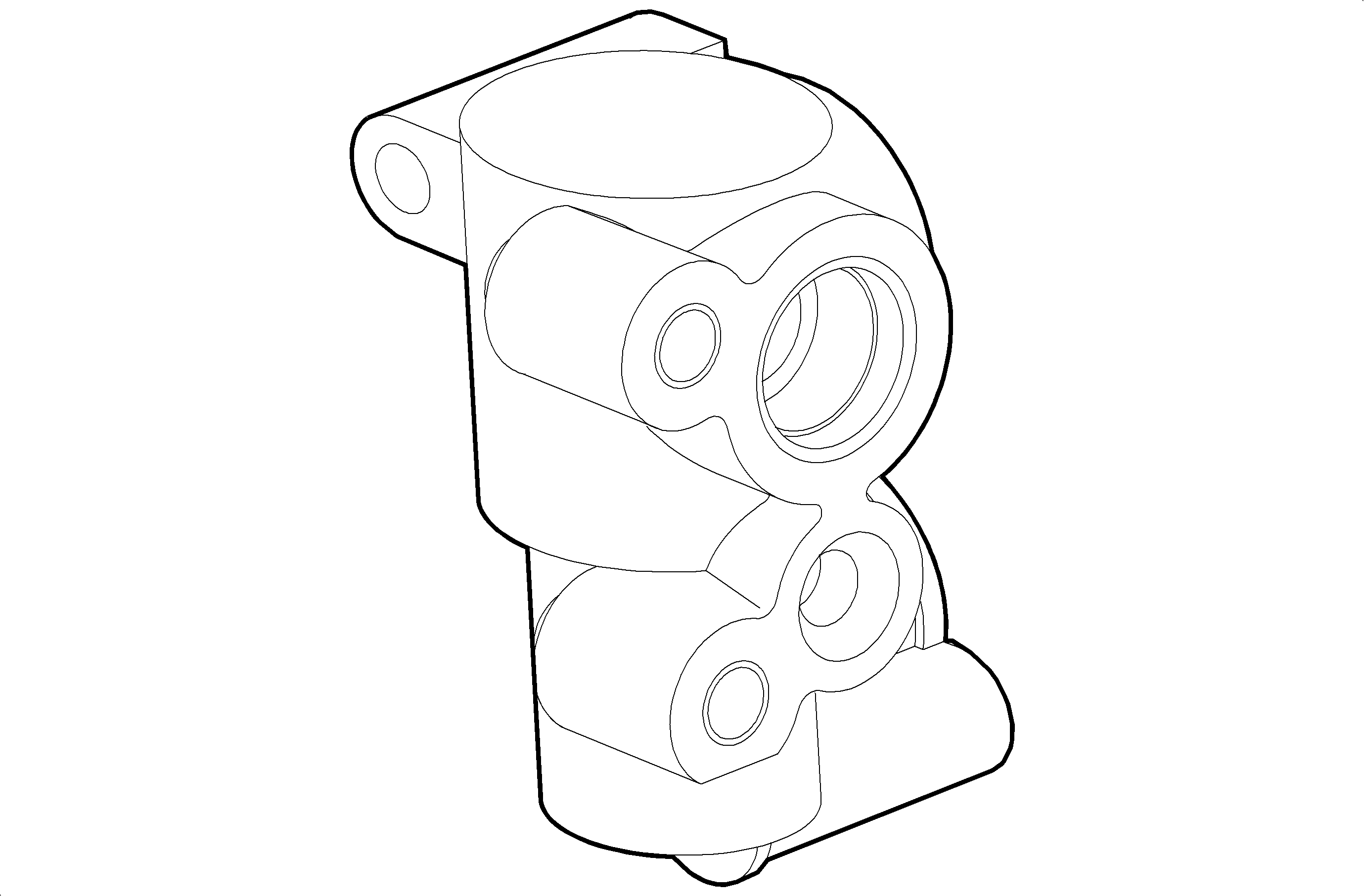
The thermal expansion valve is installed on the evaporator inlet and outlet pipes. The expansion valve converts the high-pressure liquid refrigerant from the receiver drier to a low-pressure liquid refrigerant by forcing it through a small port before entering the evaporator.
When the heat load increases or decreases, the expansion valve will supply the correct quantity of refrigerant to the evaporator for maximum heat transfer.
The expansion valve consists of the block and body.
The body includes a temperature sensor for sensing the temperature of vapor. A diaphragm transmits changes in pressure inside the temperature sensor bulb stem which is connected to the diaphragm.
The stem is tapered and moves in response to changes in the pressure inside the temperature sensor bulb. This controls the flow of refrigerant by changing the size of the valve opening.
The body has an equalizing pressure port through which the vapor pressure of the evaporator acts on the bottom of the diaphragm.
When the evaporator heat load increases, the stem is pushed down and the flow of refrigerant to the evaporator increases. As a result, the vapor pressure and temperature of the refrigerant on the evaporator outlet side changes. When the evaporator heat load decreases, the situation is reversed.
HVAC Control - General Description
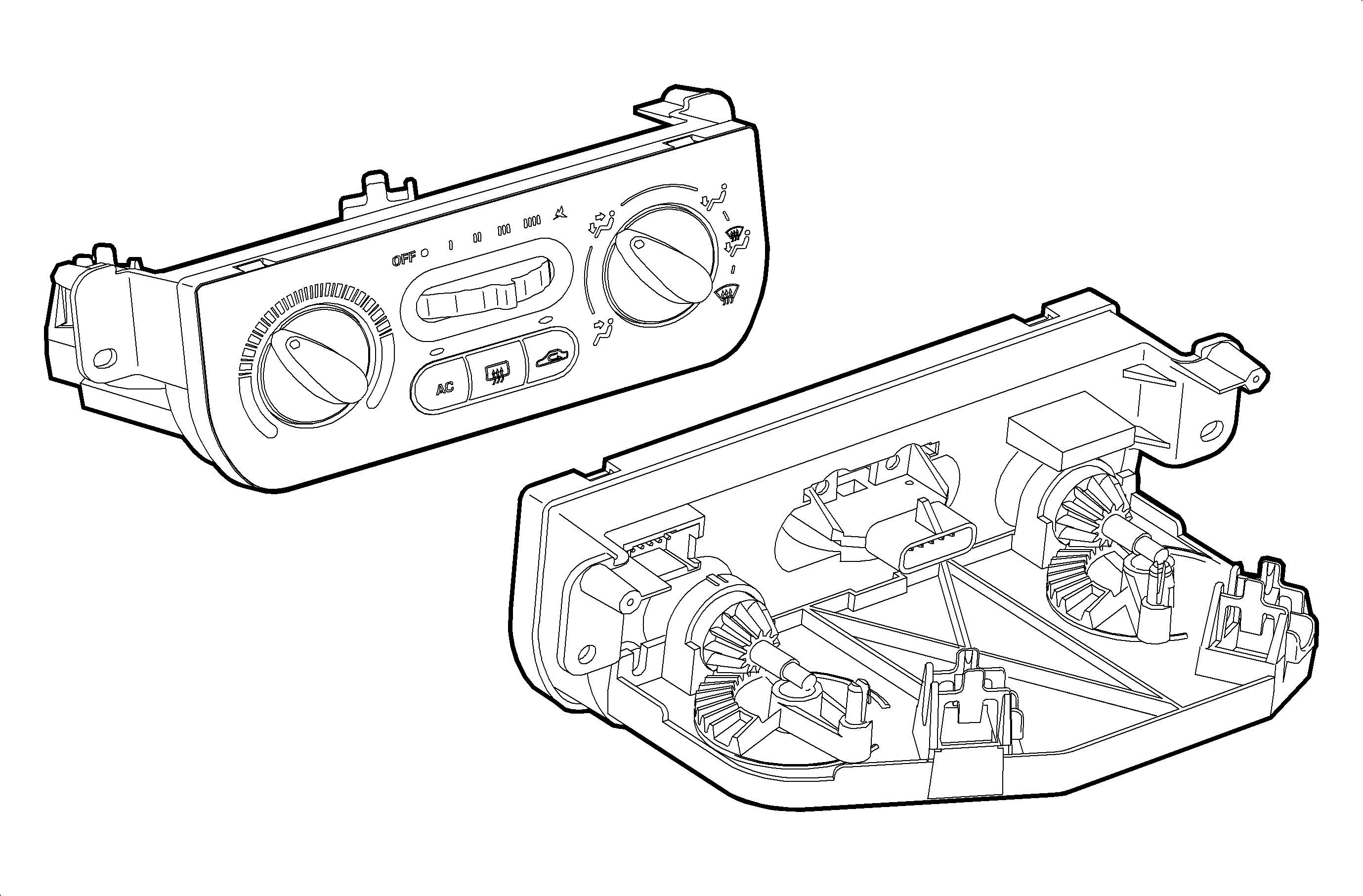
The operation of the A/C system is controlled by the buttons, rotary switch, and knobs on the HVAC control. The compressor clutch and recirc motor are controlled electrically by push buttons on the control head.
Blower speeds are controlled in all modes by a five position rotary switch. The blower, compressor, and recirc motor are not operational when the blower switch is in the Off position. The recirc function will not operate when defog/defrost is selected. The controller will return the HVAC module operation to the mode that draws fresh outside air into the vehicle.
The temperature knob controls the temperature door through a cable from the HVAC control assembly to the HVAC module. The mode knob controls the various mode positions by a cable from the HVAC control to the HVAC module.
HVAC Module - General Description (LHD Only)
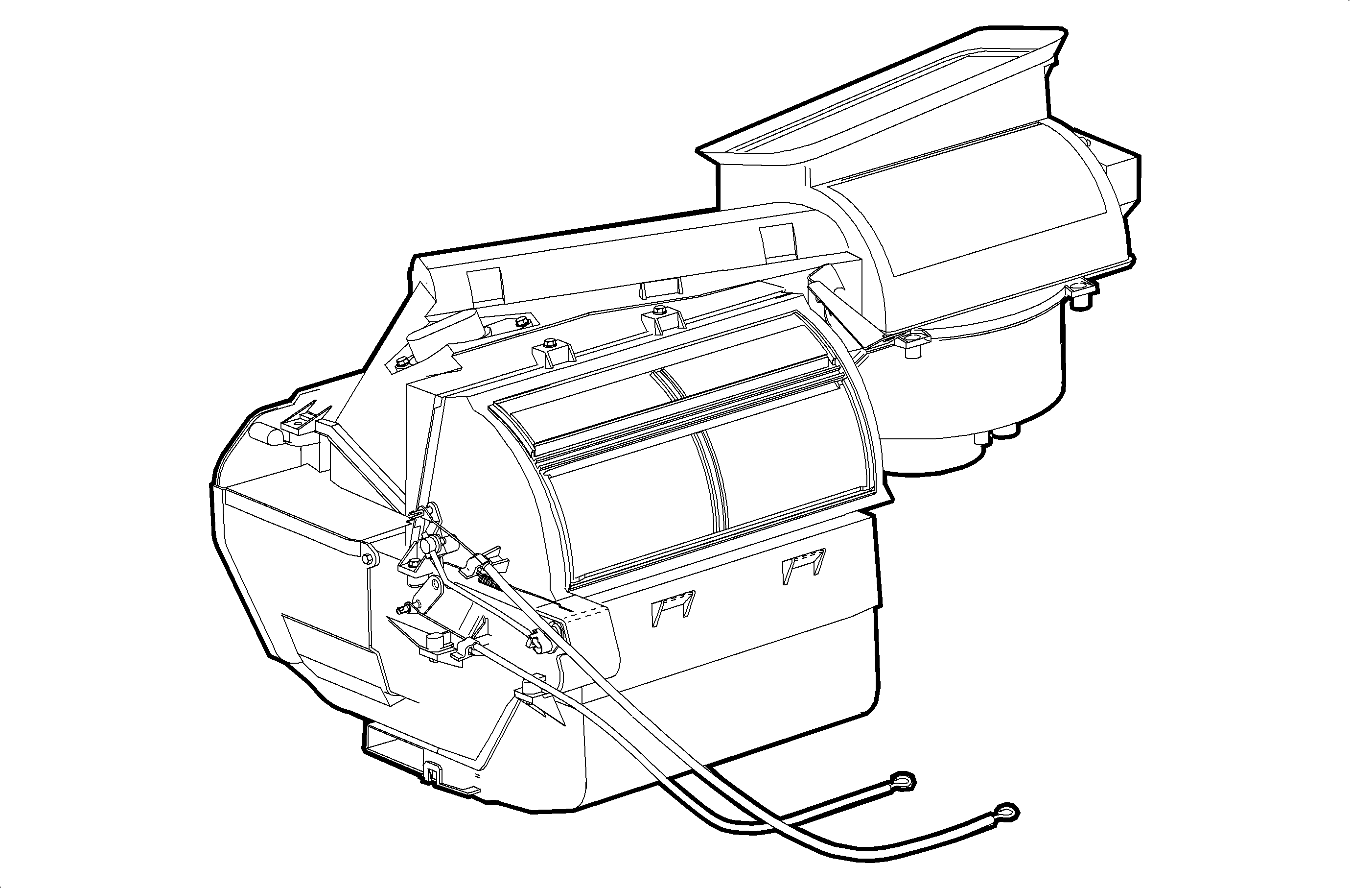
The HVAC module consists of the recirc motor, the blower motor and fan, the blower motor resistor, the heater core, and the evaporator core. The operations of these assemblies are controlled by the knobs and switches on the HVAC control panel.
Distribution of the air is controlled by the mode knobs and buttons on the control assembly. The various positions of the mode knobs and buttons direct cooled, heated, blended, outside, or inside air through the air ducts. The flow of air during the various modes of operations is as follows:
| • | Face - Instrument Panel Outlets With a Small Amount of Bleed Air to the Heater |
| • | Face and Feet - Instrument Panel Outlets, and Floor Outlets |
| • | Feet - Floor Outlets With a Small Amount of Bleed Air to Defroster |
| • | Top - Defroster Ducts With a Small Amount of Bleed Air to the Heater |
Evaporator Core
The evaporator is a device which cools and dehumidifies the air before it enters the passenger compartment. Low pressure liquid refrigerant flows through the expansion valve into evaporator. The heat in the air passing through the evaporator core is lost to the cooler surface of the core, thereby cooling the air. As the process of heat loss from the air to the evaporator core surface is taking place, the moisture (humidity) in the air condenses on the outside surface of the evaporator core and is drained off as water. Evaporator pipes are now wrapped with mastic for system noise reduction.
HVAC Module - General Description (RHD Domestic Only)
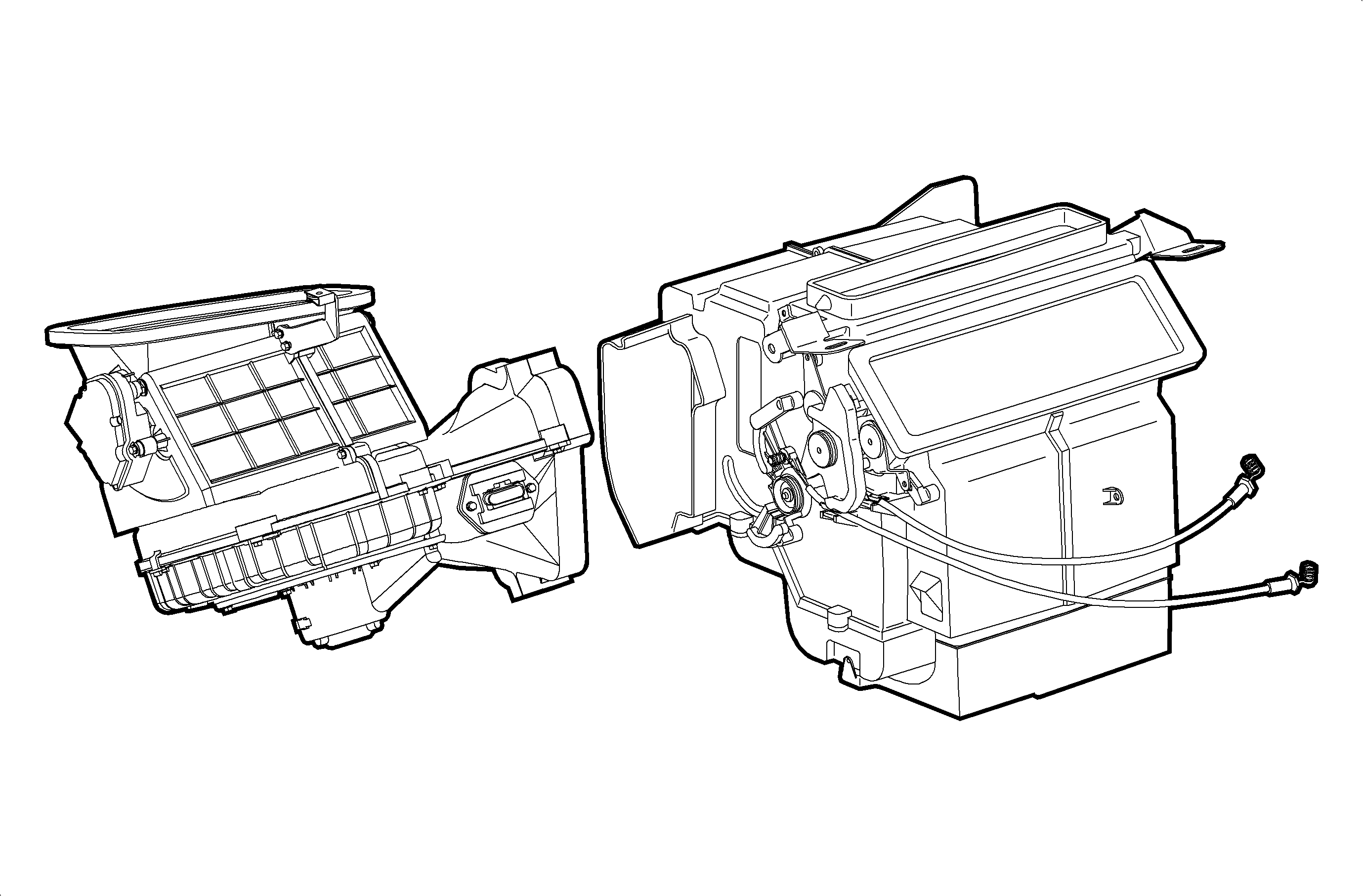
The HVAC module and blower unit consists of the recirc motor, the blower motor and fan, the blower motor resistor, the heater core, and the evaporator core. The operations of these assemblies are controlled by the knobs and switches on the HVAC control panel.
Distribution of the air is controlled by the mode knobs and buttons on the control assembly. The various positions of the mode knobs and buttons direct cooled, heated, blended, outside, or inside air through the air ducts. The flow of air during the various modes of operations is as follows:
| • | Face - Instrument Panel Outlets With a Small Amount of Bleed Air to the Heater |
| • | Face and Feet - Instrument Panel Outlets, and Floor Outlets |
| • | Feet - Floor Outlets With a Small Amount of Bleed Air to Defroster |
| • | Top - Defroster Ducts With a Small Amount of Bleed Air to the Heater |
Evaporator Core
The evaporator is a device which cools and dehumidifies the air before it enters the passenger compartment. Low pressure liquid refrigerant flows through the expansion valve into evaporator. The heat in the air passing through the evaporator core is lost to the cooler surface of the core, thereby cooling the air. As the process of heat loss from the air to the evaporator core surface is taking place, the moisture (humidity) in the air condenses on the outside surface of the evaporator core and is drained off as water.
Heater Core - General Description (LHD Only)
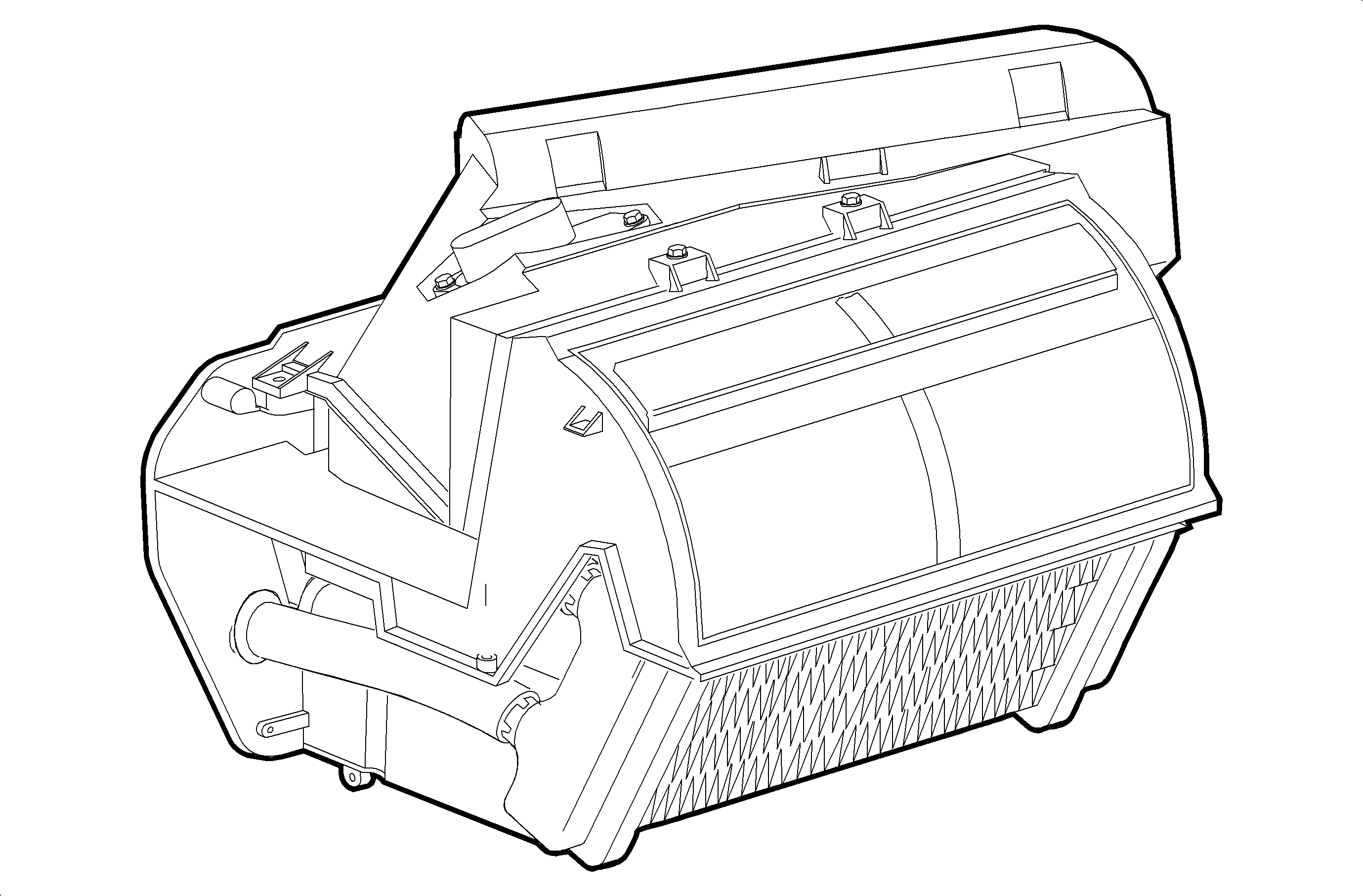
The heater core heats the air before it enters the passenger compartment. Engine coolant is circulated through the core to heat the air passing over the fins of the core.
The core is functional at all times (no water valve) and may be used to temper air in A/C mode as well as heat, vent, bi-level, and defrost.
Heater Core - General Description (RHD Domestic Only)
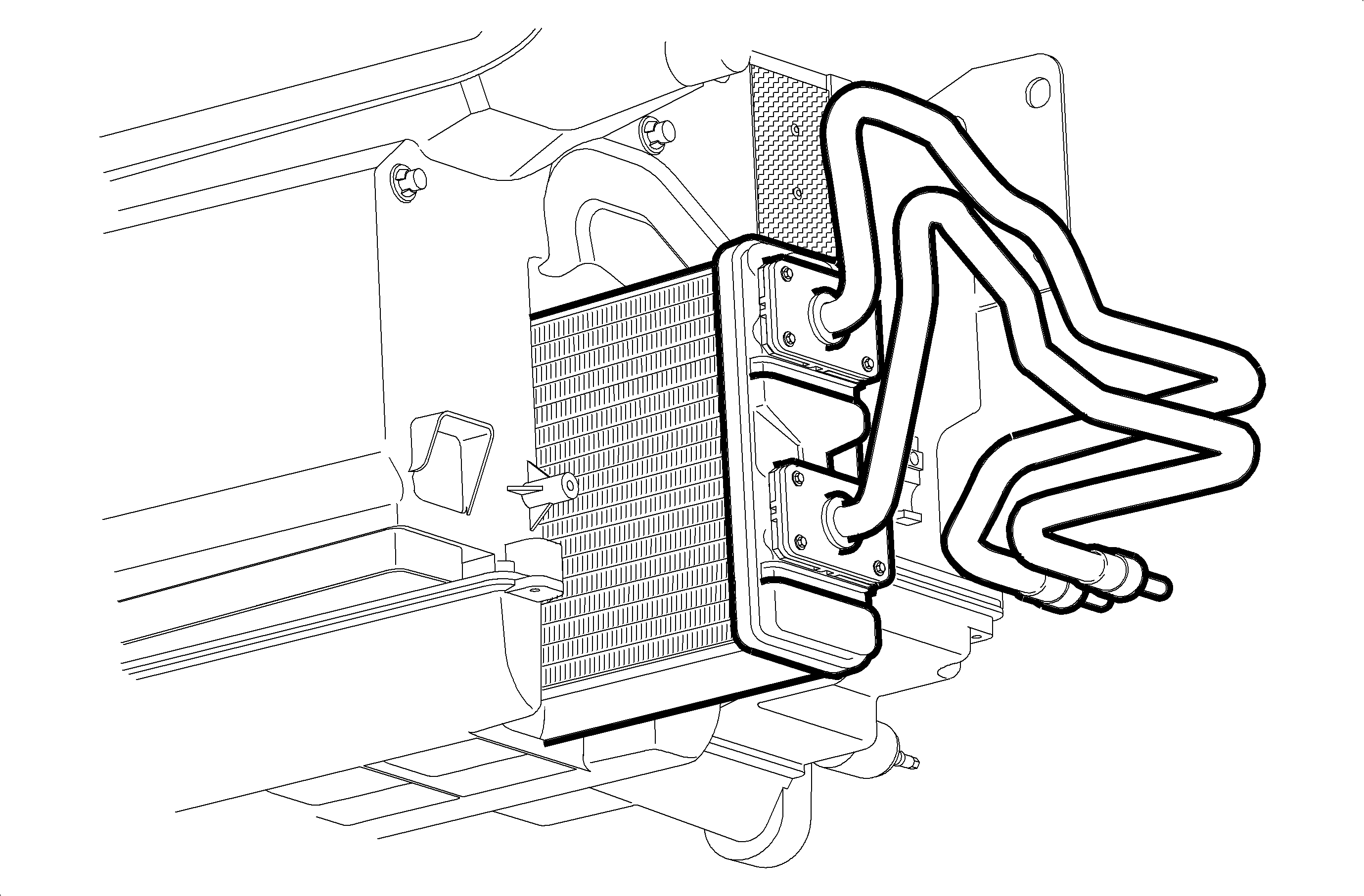
The heater core heats the air before it enters the passenger compartment. Engine coolant is circulated through the core to heat the air passing over the fins of the core.
The core is functional at all times (no water valve) and may be used to temper air in A/C mode as well as heat, vent, bi-level, and defrost.
Recirc Motor - General Description (LHD Only)
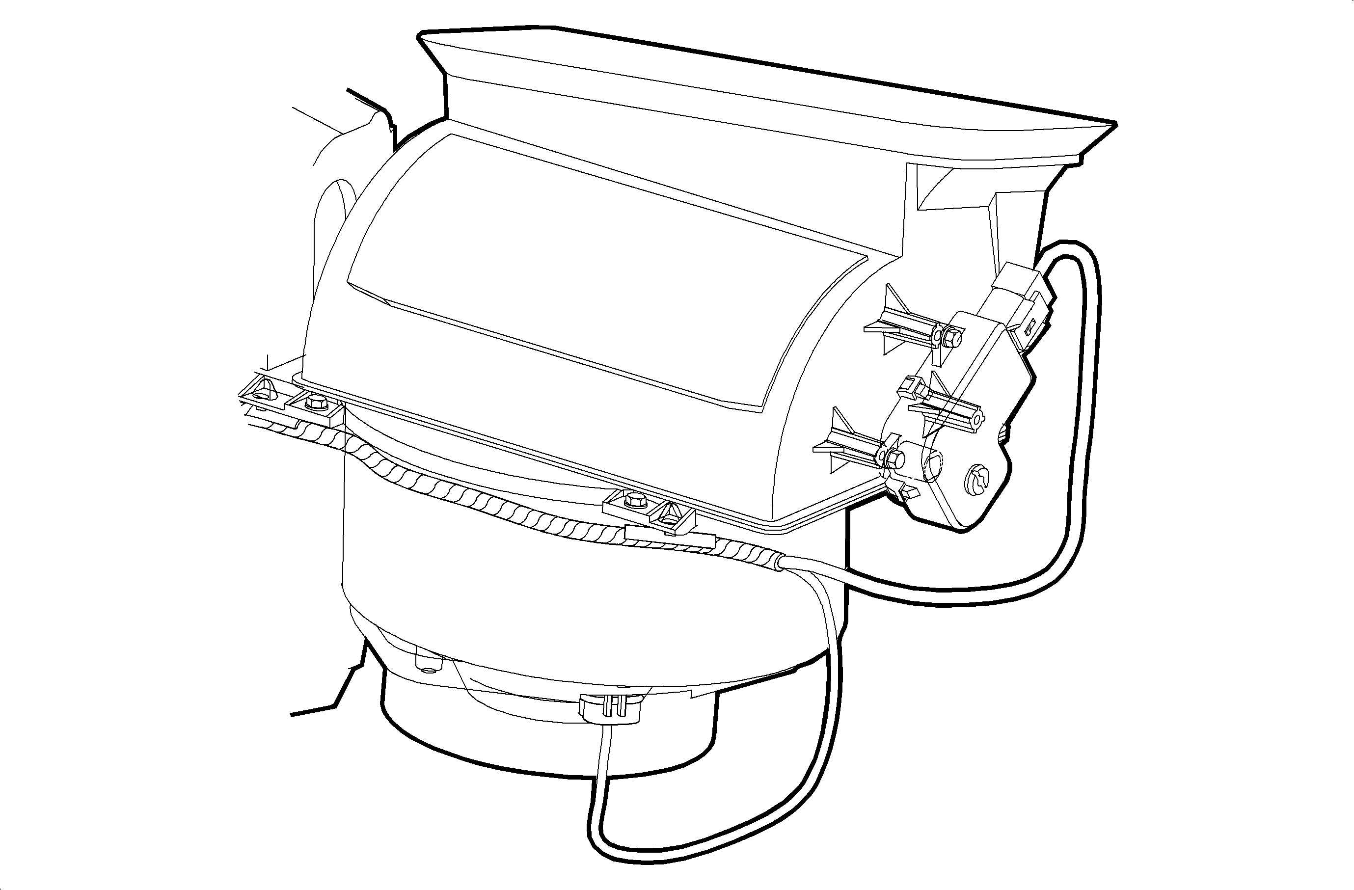
The recirc motor rotates the valve between inside and outside air. When recirc is activated, the motor allows the air inside the passenger compartment to be drawn back into the HVAC module.
Some outside air is also drawn in. When recirc is not activated fresh outside air is drawn into the system.
Recirc Motor - General Description (RHD Domestic Only)
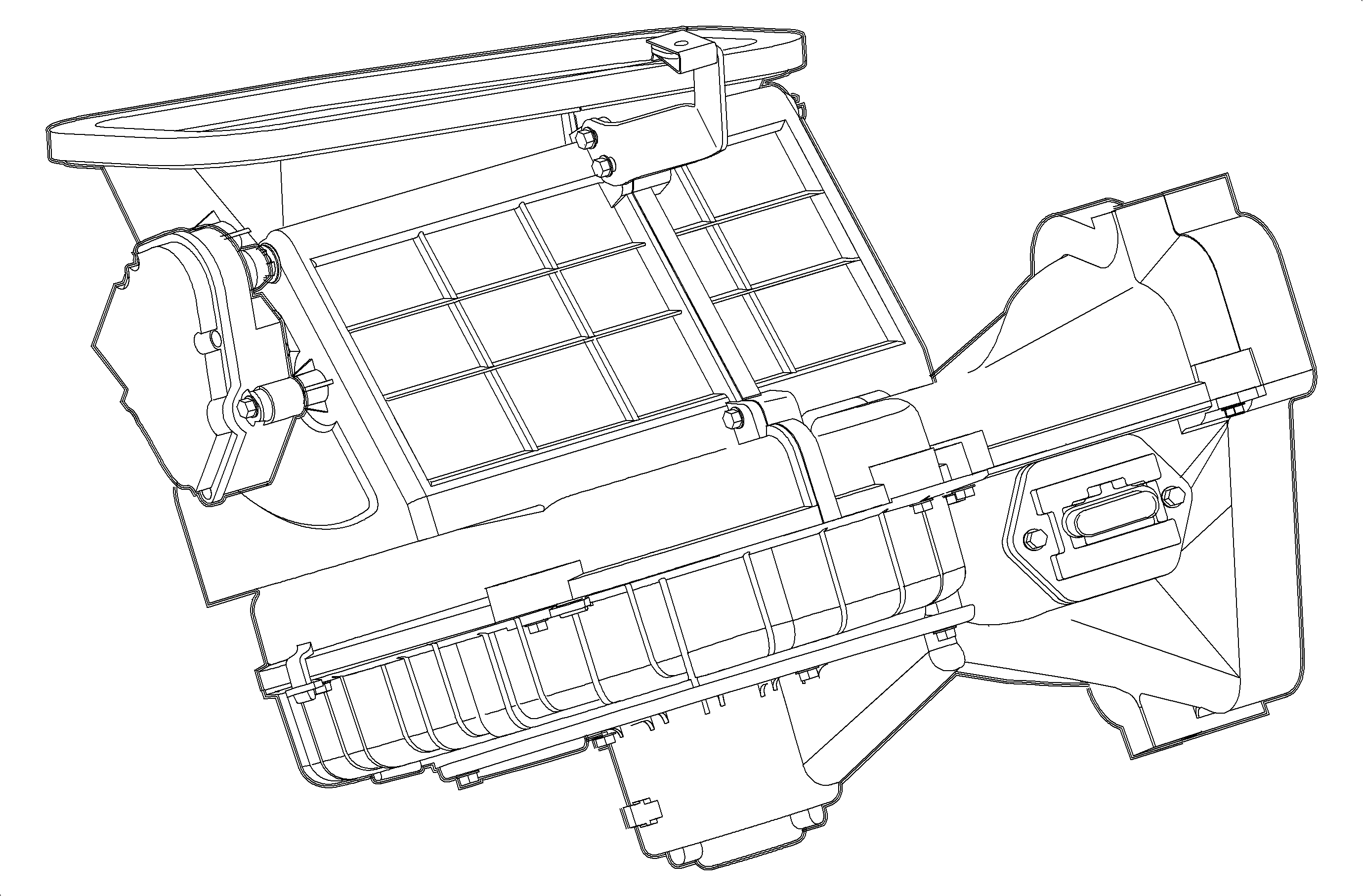
The recirc motor rotates the valve between inside and outside air. When recirc is activated, the motor allows the air inside the passenger compartment to be drawn back into the HVAC module. Some outside air is also drawn in. When recirc is not activated fresh outside air is drawn into the system.
Blower Motor - General Description (LHD Only)
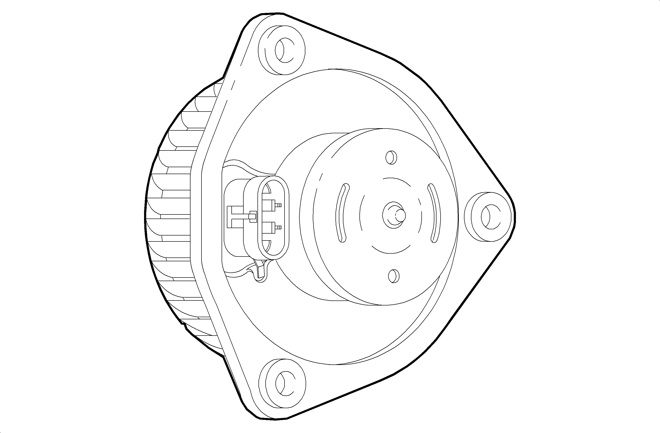
The blower motor is a permanent magnet motor with a squirrel cage fan. Its purpose is to provide air flow to the passenger compartment. The blower speeds are controlled in all modes by a five position rotary switch.
The blower motor and fan is a balanced assembly. Weights could be visible on the fan cage.
All vehicles have a blower motor cover to reduce motor noise.
Blower Motor - General Description (RHD Domestic Only)
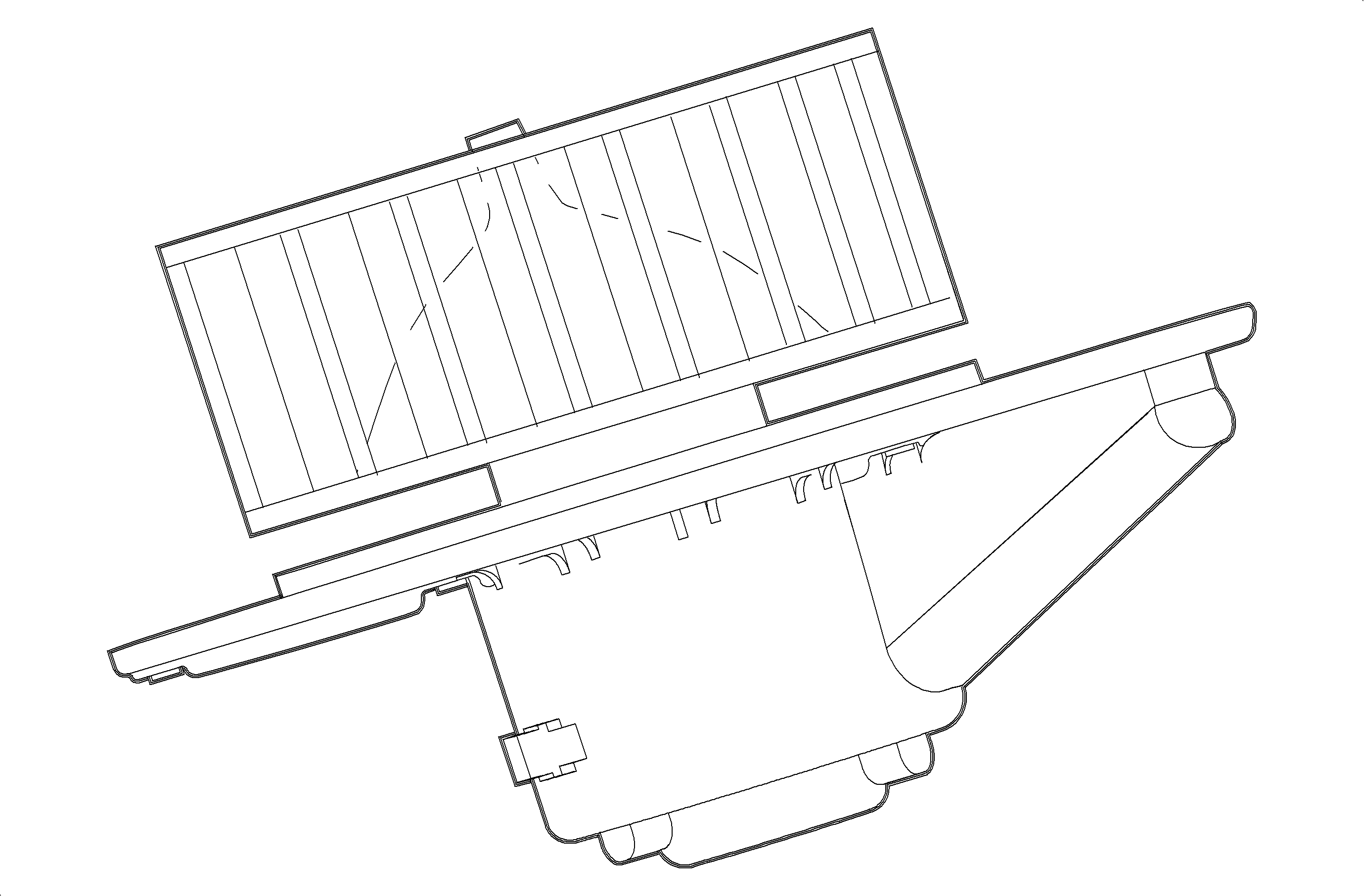
The blower motor is a permanent magnet motor with a squirrel cage fan. Its purpose is to provide air flow to the passenger compartment. The blower speeds are controlled in all modes by a five position rotary switch.
Blower Motor Resistor - General Description (LHD Only)
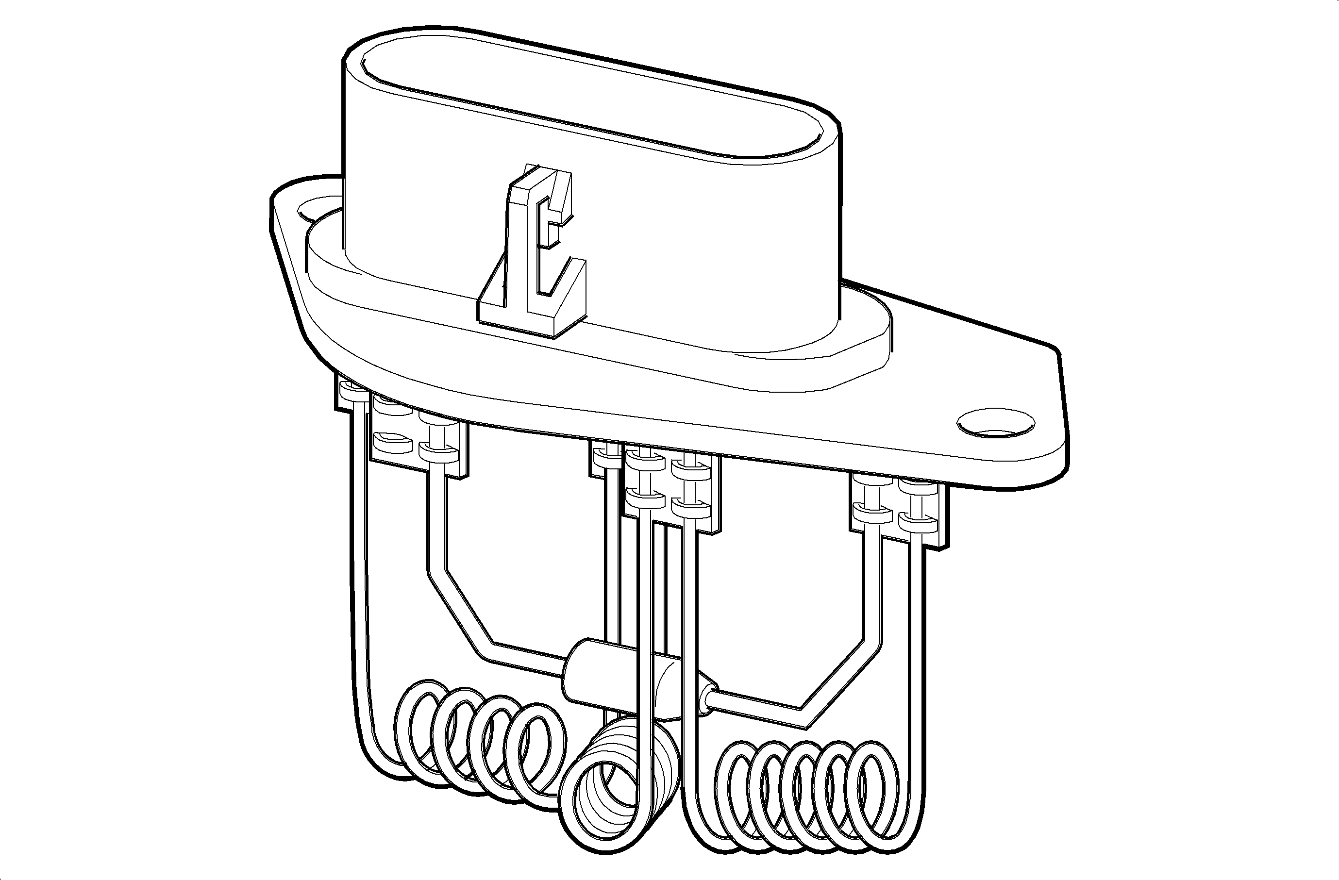
The blower motor resistor is in series to the blower motor. Its purpose is to control the speed (or RPM) of the blower. The resistors allow for the selection of blower speeds, LO, M1 and M2.
Blower Motor Resistor - General Description (RHD Domestic Only)
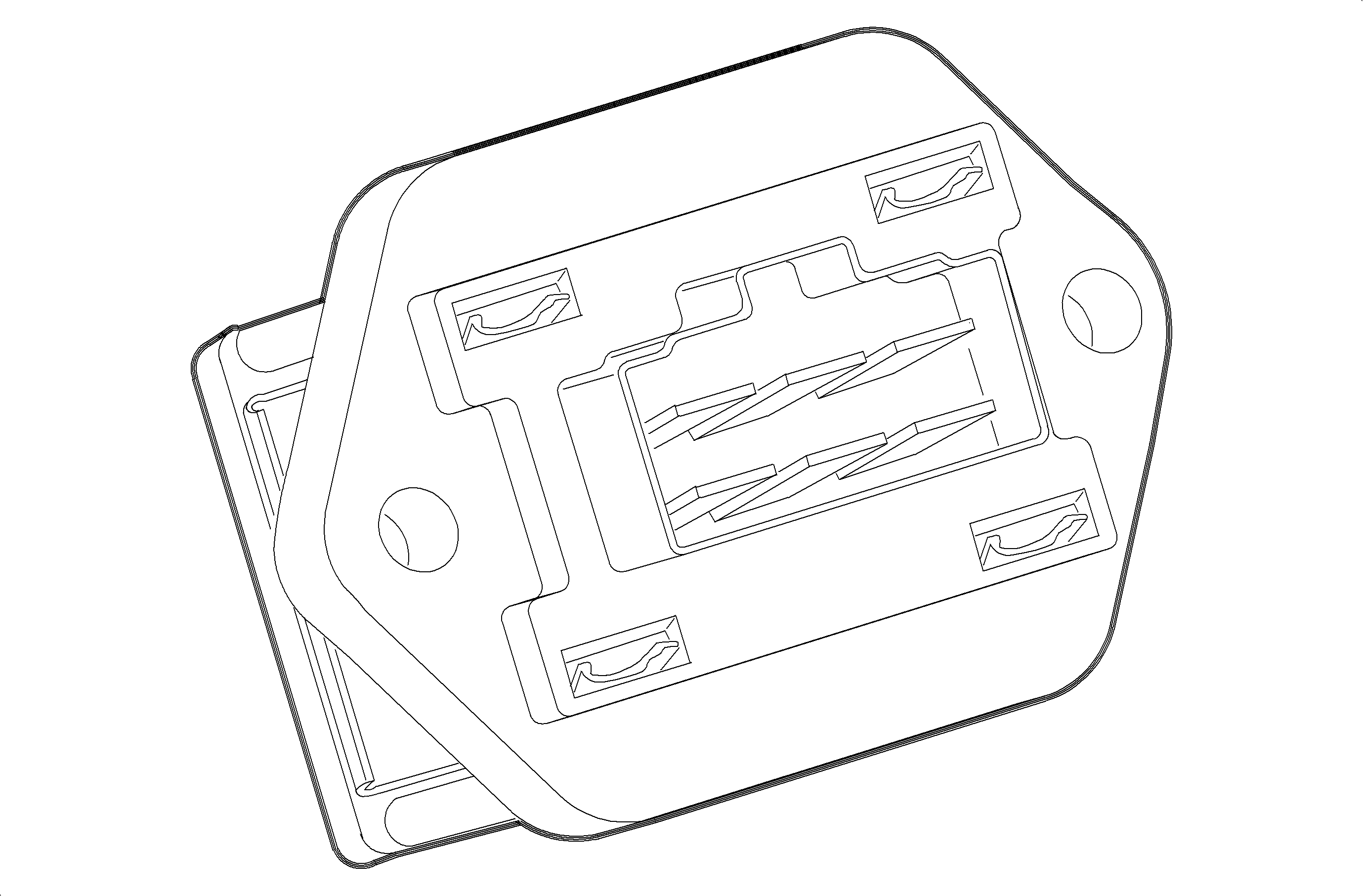
The blower motor resistor is in series to the blower motor. Its purpose is to control the speed (or RPM) of the blower. The resistors allow for the selection of blower speeds, LO, M1 and M2.
Ventilation Ducts - General Description (LHD Only)
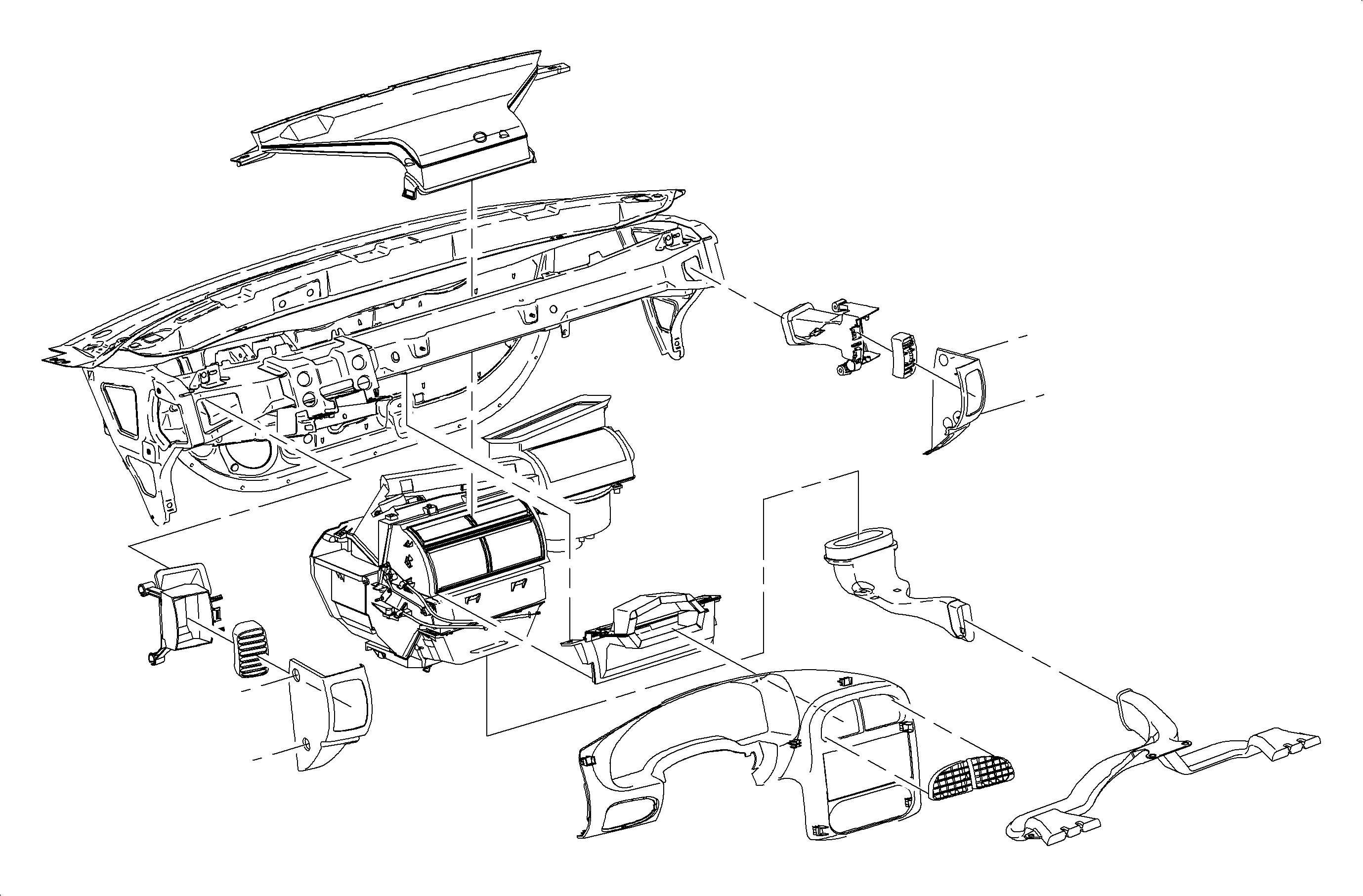
The air is directed to the various instrument panel outlets by the ventilation ducts. The flow of air depends on the setting of the controls. The defroster duct is a one piece unit connected to the top of the HVAC module. The center air duct is connected to the front of the HVAC module. The left cross car beam duct is connected to the left side of the center air duct. The cross car beam duct leads to the air duct, followed by the outlet assembly and the end cap. The right cross car beam duct is connected in a similar way. The center air outlets are connected to the center air duct.
The air outlet vanes on the attached assembly enable the passenger to direct the air to where it is desired or to shut off outlet air flow. The lower heater duct is connected to the bottom of the HVAC module. The rear heater air duct is tapped off of the lower heater duct. The rear heater duct supplies air to both the left and right sides of the back seat floor.
The SC model does not have rear seat heater ducts.
Ventilation Ducts - General Description (RHD Domestic Only)
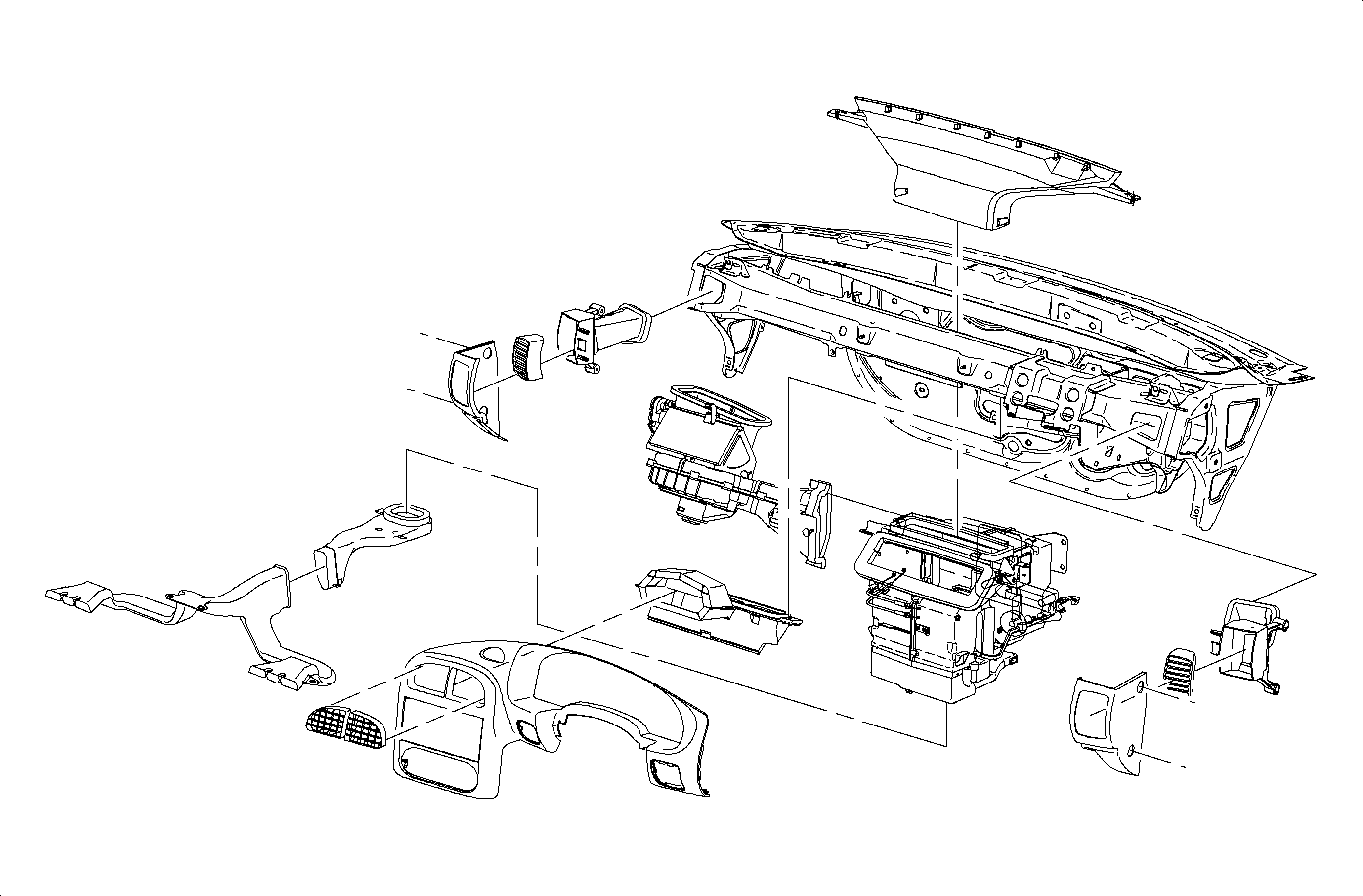
The air is directed to the various instrument panel outlets by the ventilation ducts. The flow of air depends on the setting of the controls. The defroster duct is a one piece unit connected to the top of the HVAC module. The center air duct is connected to the front of the HVAC module. The left cross car beam duct is connected to the left side of the center air duct. The cross car beam duct leads to the air duct, followed by the outlet assembly and the end cap. The right cross car beam duct is connected in a similar way. The center air outlets are connected to the center air duct.
The air outlet vanes on the attached assembly enable the passenger to direct the air to where it is desired or to shut off outlet air flow. The lower heater duct is connected to the bottom of the HVAC module. The rear heater air duct is tapped off of the lower heater duct. The rear heater duct supplies air to both the left and right sides of the back seat floor.
