Harsh Shifts, No Shifts, and/or No TCC Operation with Transaxle Releated DTCs Set

| Subject: | Harsh Shifts, No shifts, and/or No TCC Operation with Transaxle Related DTCs Set (Replace Transaxle Connector and Harness) |
| Models: | 1994 - 2001 Saturn S-Series vehicles with automatic transaxles (RPO MP6 or MP7) |
Condition
Some customers may comment about harsh transaxle shifting and/or erratic transaxle shifting. One or more transaxle-related diagnostic trouble codes (DTCs) may have set. The Malfunction Indicator Lamp (MIL) may or may not be illuminated depending on what DTC is set. The malfunction Indicator Lamp (MIL) may or may not be illuminated depending on what DTC is set.
One or more of the following DTCs may be set and indicate what circuits are affected:
DTC | Circuit Affected | Wire Color |
|---|---|---|
P0740 - TCC Solenoid Circuit Low Voltage P0741 - TCC System Stuck Off | Circuit - 422 Circuit - 1526 | Tan/Blk Wht/Blk |
P0746 - PC Solenoid Circuit Low Voltage | Circuit - 1525 Circuit - 1530 | Red Drk Blu |
P0756 - Shift Solenoid 2 Control Circuit Low Voltage P0732 - Incorrect 2nd Gear Ratio | Circuit- 1526 Circuit - 1222 | Wht Lt Grn |
P0761 - Shift Solenoid 3 control Circuit Low Voltage P0733 - Incorrect 3rd Gear Ratio | Circuit - 1527 Circuit - 1223 | Lt Grn/Blk YelL/Blk |
P0766 - Shift Solenoid 4 Control Circuit Low Voltage P0734 - Incorrect 4th Gear Ratio | Circuit - 1527 Circuit - 898 | Lt/Grn Ppt |
P0789 - Shift Timing Solenoid Control Circuit Intermittent | N/A | N/A |
For all DTCs listed above, if one specific solenoid DTC is set, diagnose those DTCs first.
Cause
Due to normal powertrain vibration, the transaxle wiring may flex and cause a circuit to open inside wire insulation near transaxle connector. In some cases, insulation will look distorted at point of open circuit.
Correction
Perform procedure in this bulletin to replace transaxle connector (P/N 21024415).
Procedure:
Important: For intermittent or difficult to duplicate transaxle shift complaints, perform this procedure to verify transaxle wiring integrity.
- Verify diagnostic trouble code (DTC) is current. Once DTC has been identified, refer to appropriate diagnostic flow chart for circuit number identification. (Refer to appropriate model year Automatic Transaxle service manual for diagnostic flow charts.)
- Remove air inlet duct.
- Remove battery.
- Remove battery tray.
- Loosen transaxle electrical connector bolt and disconnect transaxle electrical connector.
- Disconnect transaxle range switch connectors.
- Remove electrical tape from wiring harness from transaxle electrical connector to main engine harness approximately 20-25 cm [8-10 in.]).
- Visually inspect circuits associated with DTC. Inspect wires for damaged or deformed insulation from transaxle electrical connector to main engine harness (up to 25 cm [10 in.] away from connector).
- Once location of open circuit is identified, replace transaxle connector in its entirety (all ten circuits) with replacement transaxle connector (P/N 21024415).
- Connect transaxle range switch connectors.
- Connect transaxle electrical connector, and torque transaxle electrical connector bolt.
- Clear DTC(s) and retest.
- Clear DTC(s) again.
- Check for intermittent circuit fault. Wiggle harness near connector while performing diagnostic test on affected circuit.
- Using high quality electrical tape, re-wrap transaxle connector circuit branch from main harness breakout to connector.
- Install battery tray.
- Install battery
- Install air inlet duct.
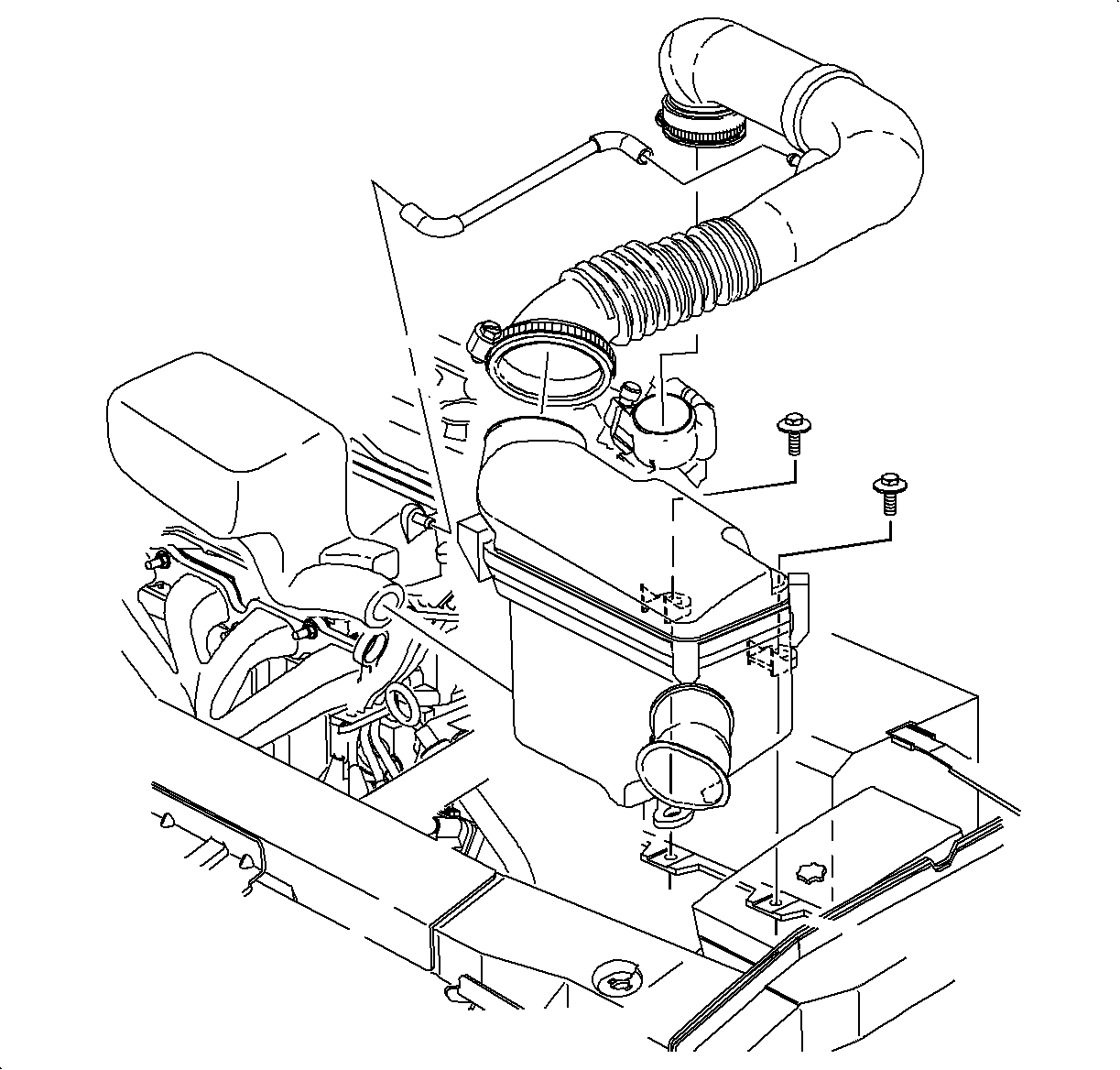
Important: Illustration shown is for DOHC engine (RPO LL0); SOHC engine (RPO L24) is similar.
| 2.1. | Open clamp at throttle body |
| 2.2. | Disconnect fresh air hose at air duct. |
| 2.3. | Remove air cleaner housing cover and air duct. |
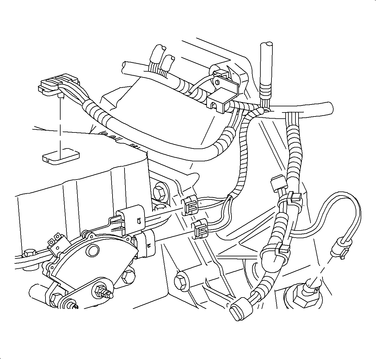
Important: A sewing "seam stripper" is an excellent tool for removing tape from a wire harness. It cuts the tape without damage to the wires under the tape.
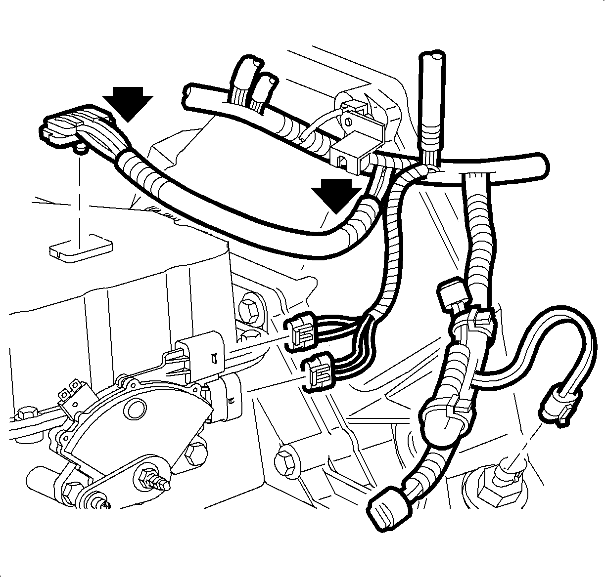
Important: If wires are broken inside insulation, outside of insulation may appear to be thin in one area, stretched or discolored.
| • | If there is visual evidence of wire damage and the location of the open circuit can be identified, continue with next step. |
| • | If there is no evidence of wire damage, physically inspect each wire by sliding fingers along entire length of wire and feel for abnormalities or depressions. |
| - | If wire damage is located during physical inspection, continue with next step. |
| - | If no wire damage is located during physical inspection, continue to step 10. |
| Important: When splicing in new connector, stagger crimp-and-seal connectors so they are not all in same location. Staggering crimp-and-seal connectors will allow for a better finished look. |
| 9.1. | Cut transaxle connector circuit branch within 38 mm (1.5 in.) of main harness to ensure any other possibly affected circuits are repaired. Discard transaxle connector. |
| 9.2. | Remove insulation from ends of cut wires and new transaxle connector harness. Recommended strip length is 4.8 mm (3/16 in.) for 12-20 gauge wire and 9.5 mm (3/8 in.) for 22 gauge wire so it can be folded in half. Care must be used when stripping wire to prevent cutting the wire strands. |
* Can be ordered through Delphi-Packard by calling 1-800-PACKARD (1-800-722-5273).
** Can be ordered through Saturn Special Tool Catalog. Found with J44020 Terminal Repair Kit.
| Important: For the wiring used in Saturn vehicles, it is recommended that only approved Packard Electric Crimp and Seal Splice Sleeves (or equivalent) be used. |
| 9.3. | Using a Saturn-approved crimp and seal splice sleeve (found in terminal repair kit J44020), position stripped ends of wires in sleeve until wires hit stop. |
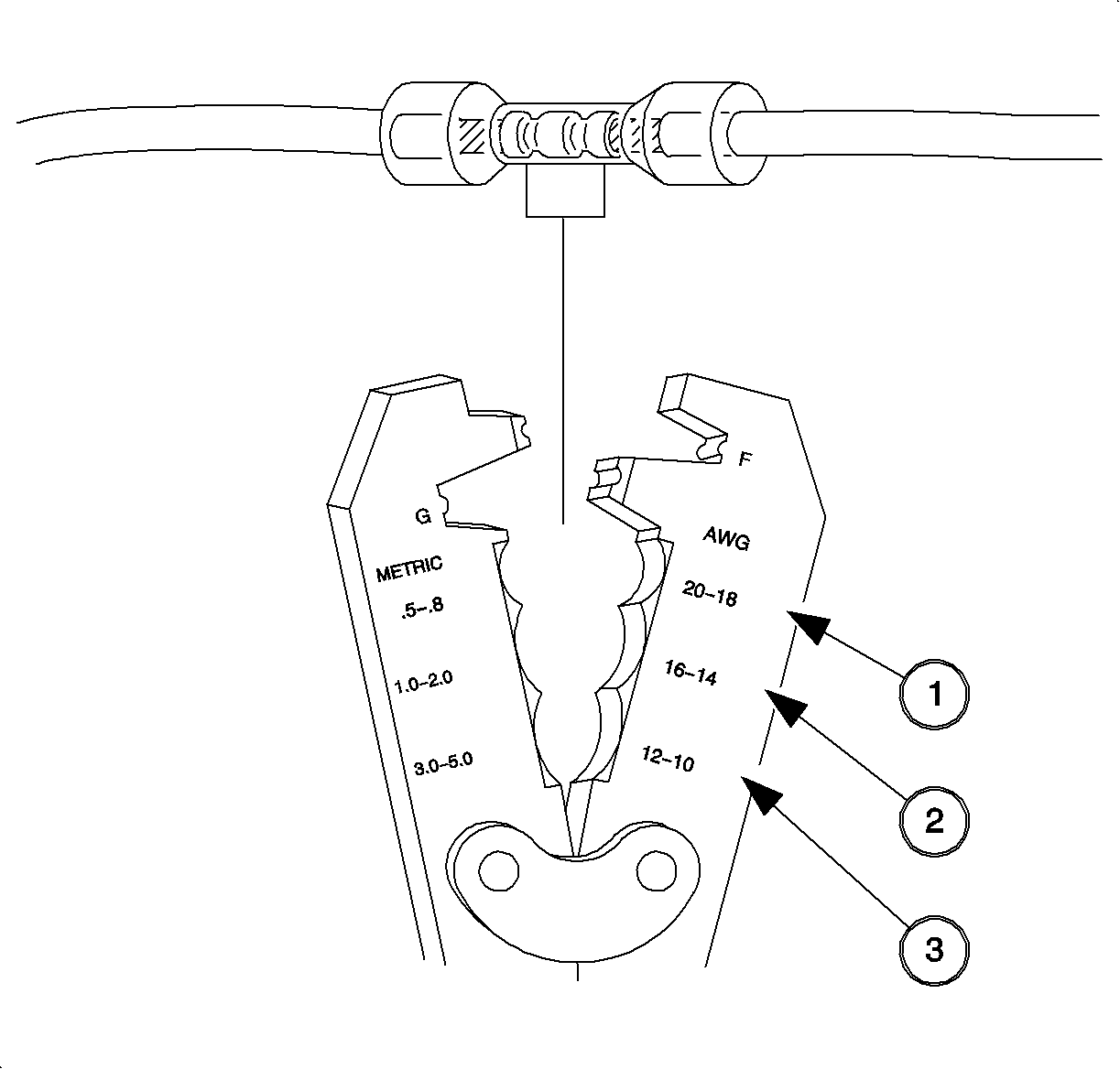
| 9.4. | Hand crimp splice sleeve using correct jaws in Packard crimper (P/N 12085155) or appropriate crimping tool. Gently tug on wires to ensure they are secure before applying heat to seal sleeve. |
| Caution: DO NOT USE A MATCH OR OPEN FLAME TO APPLY HEAT TO SPLICE SLEEVE. |
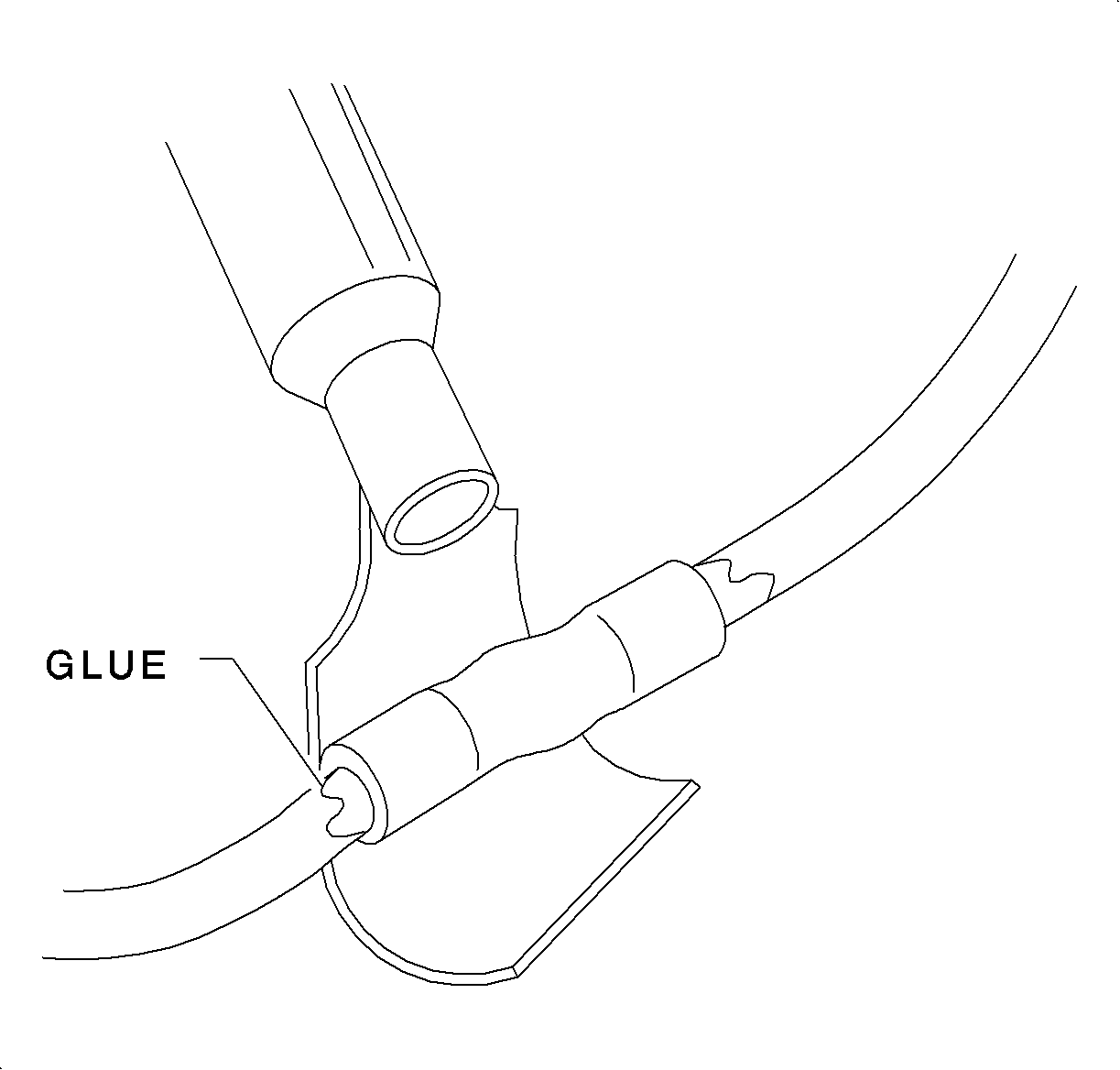
| 9.5. | Apply heat using Ultratorch ® or heat gun. Heat to 175° C (347° F) until glue flows around edges of sleeve. |
| 9.6. | Check for continuity in the wire and verify the repair. |

Notice: Do not over-tighten or damage tot he connector plate may occur.
Tighten
Transaxle Electrical Connector Bolt: 3 N·m (27 in lb)
| • | If a DTC is reset, refer to diagnostic aids in appropriate model year Automatic Transaxle service manual and continue with next step. |
| • | If no DTCs are rest, go to step 15. |
| • | If DTC sets, refer to appropriate diagnostic flow chart for circuit number identification. (Refer to appropriate model year Automatic Transaxle service manual for diagnostic flow charts.) Continue with next step after diagnostics have been completed. |
| • | If DTC does not set, refer to diagnostic aids in appropriate model year Automatic Transaxle service manual for intermittent conditions. Continue with next step after diagnostics have been completed. |
Tighten
Battery Tray-to-Vehicle Bolts: 10 N·m (89 in lbs)
Tighten
Battery Terminal Bolts: 17 N·m (13 lb ft)

Important: Illustration shown is for DOHC engine (RPO LL0); SOHC engine (RPO L24) is similar.
| 18.1. | Install air duct and air cleaner housing cover. Attach air cleaner housing clips. |
| 18.2. | Install clamp at throttle body. |
Tighten
Air Cleaner duct-to-Throttle Body Clamp: 2 N·m (18 in lb)
| 18.3. | Connect fresh air hose to air duct. |
PARTS REQUIREMENTS:
21024415 Connector -- Inline- To A/Trns Shift Lk Cont Sol
CLAIM INFORMATION:
To receive credit for this repair during the warranty coverage period, submit a claim through the Saturn Dealer System for N6045 (Wiring and/or Connector, Automatic Transaxle [Engine Compartment] -- Repair or Replace). If another procedure is performed, refer tot he appropriate Electronic Labor Time Guide for the correct Labor Operation Code and time.
WIRE SIZE | .3 | .50 | .80 | 1.0 | 2.0 | 3.0 | 5.0 | |
|---|---|---|---|---|---|---|---|---|
GAGE | 22 | 20 | 18 | 16 | 14 | 12 | 10 | |
Packard P/N* | Special Tools P/N** | |||||||
12089189 | (217670) | -Salmon- | ||||||
12089190 | (217671) | -Blue- | ||||||
12089191 | (217672) | -Yellow- | ||||||
NOTE: This table belong in between step 9.2 and 9.3
