
| Subject: | Audible Warning Chime Distorted (Install Foam Block Tape in Body Control
Module [BCM]) |
| Models: | 2000-2002 Saturn S-Series vehicles equipped with remote keyless entry (RKE)
(RPO AUO) |
Condition
Some customers may comment that the audible warning chime sounds distorted.
This condition is most noticeable when the ignition switch is turned On after the
vehicle interior has been exposed to high ambient temperatures and/or direct sunlight.
Cause
Remote keyless entry (RKE) antenna located on circuit board inside body control
module (BCM) can contact BCM case housing causing chime to sound distorted. Elevated
BCM case housing temperature can intensify distorted chime tone.
Correction
Install two foam pieces (P/N 21160169) to BCM cover following the procedure
in this bulletin.
Procedure
Caution: WHEN YOU ARE PERFORMING SERVICE ON OR NEAR THE SIR COMPONENTS OR THE SIR WIRING,
YOU MUST DISABLE THE SIR SYSTEM. REFER TO SIR DISABLE/ENABLE PROCEDURE. FAILURE TO
FOLLOW THE CORRECT PROCEDURE COULD CAUSE AIR BAG DEPLOYMENT, PERSONAL INJURY, OR UNNECESSARY
SIR SYSTEM REPAIRS.
- Disable the SIR system.
| 1.1. | Turn steering wheel so that vehicle's wheels are pointing straight ahead. |
| 1.2. | Turn ignition switch to OFF and remove key. |
| 1.3. | Remove AIR BAG fuse from instrument panel fuse block (IPFB). |
| 1.4. | Disconnect driver (YEL 2-way) connector, clipped
to steering column brace. |
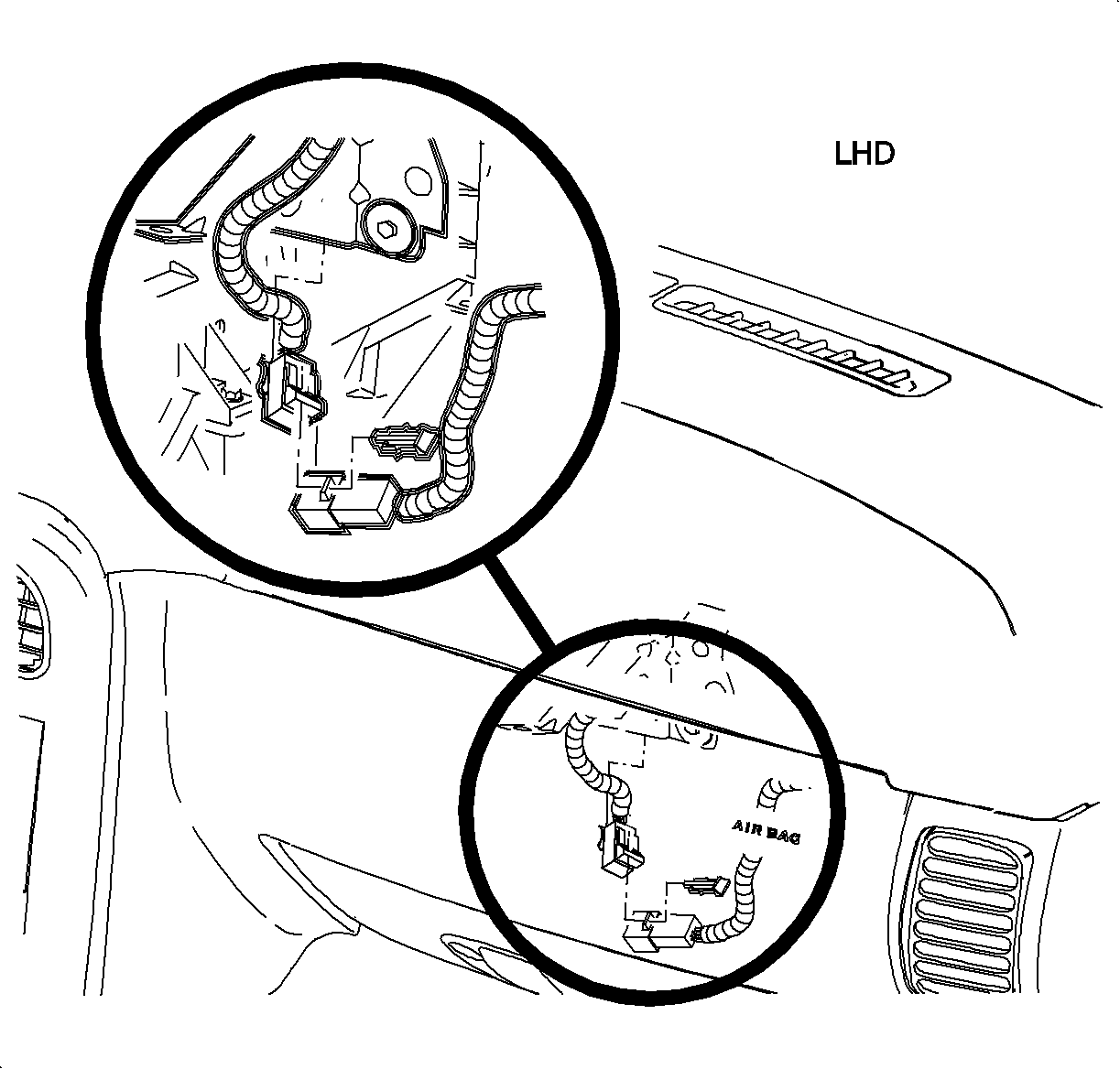
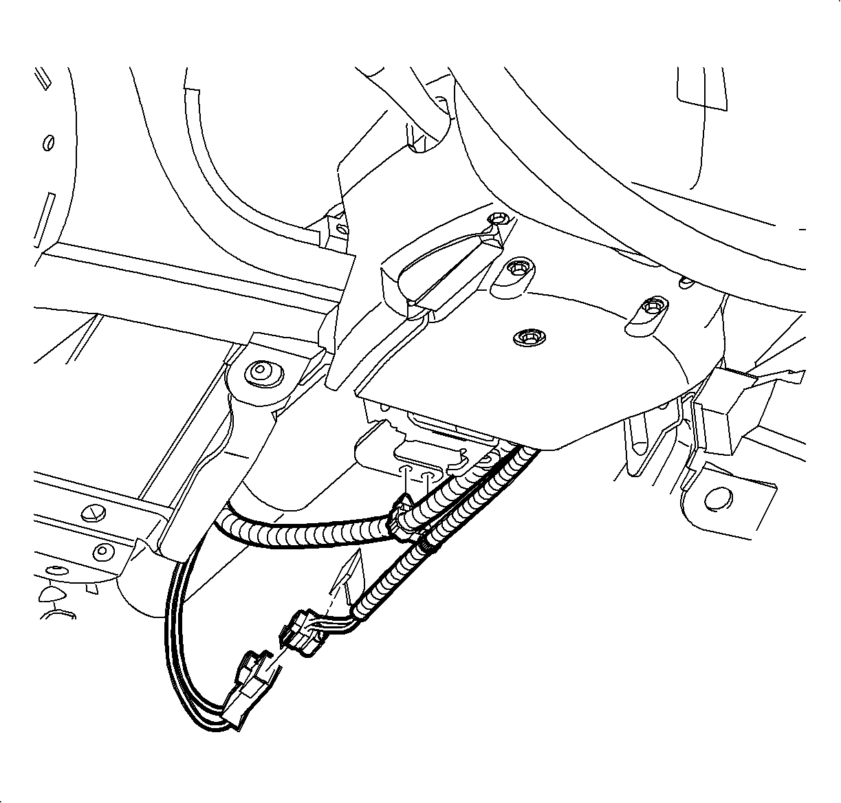
| | Important: Passenger disconnect is accessible from underside of I/P.
|
| 1.5. | Detach clip holding passenger (YEL 2-way) connector to metal brace, near HVAC
fan. |
| 1.6. | Disconnect passenger (YEL 2-way) connector. |
Notice: Be careful not to damage VIN plate when removing or replacing upper trim panel.
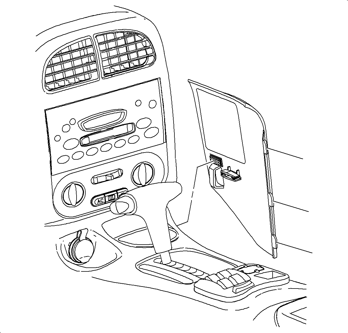
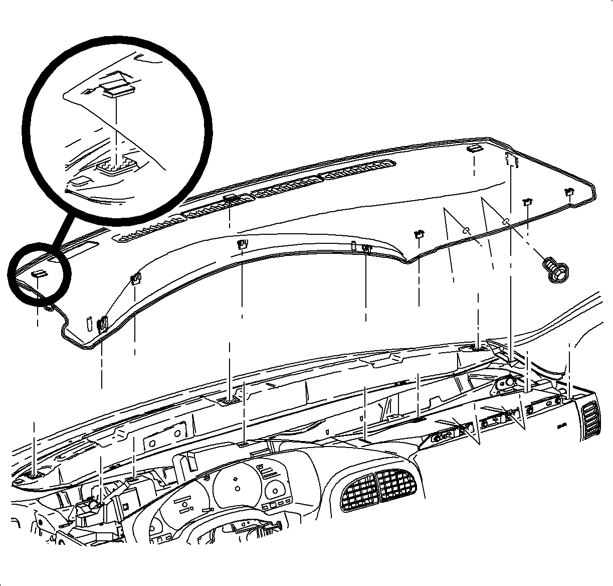
- Remove instrument panel upper trim:
| 2.1. | Remove screws located under upper trim panel on passenger's side of vehicle. |
| 2.2. | Disengage clips at locations by grasping edges of upper trim panel and
lifting up. |
| 2.3. | Disengage hook-and-loop fastener attachments at rear of upper trim panel
by reaching under panel and lifting straight up. |
| 2.4. | Raise upper trim panel enough to clear VIN plate. |
Notice: Follow the electrostatic discharge (ESD) precautions when handling BCM. Refer
to "Electrostatic Discharge (ESD)" in the Body Control Module section of the 2000/2002
S-Series Body/Electrical Volume II service manual.
- Grasp BCM under connector side and pull upward and back. Rock module from side
to side to disengage adhesive material.
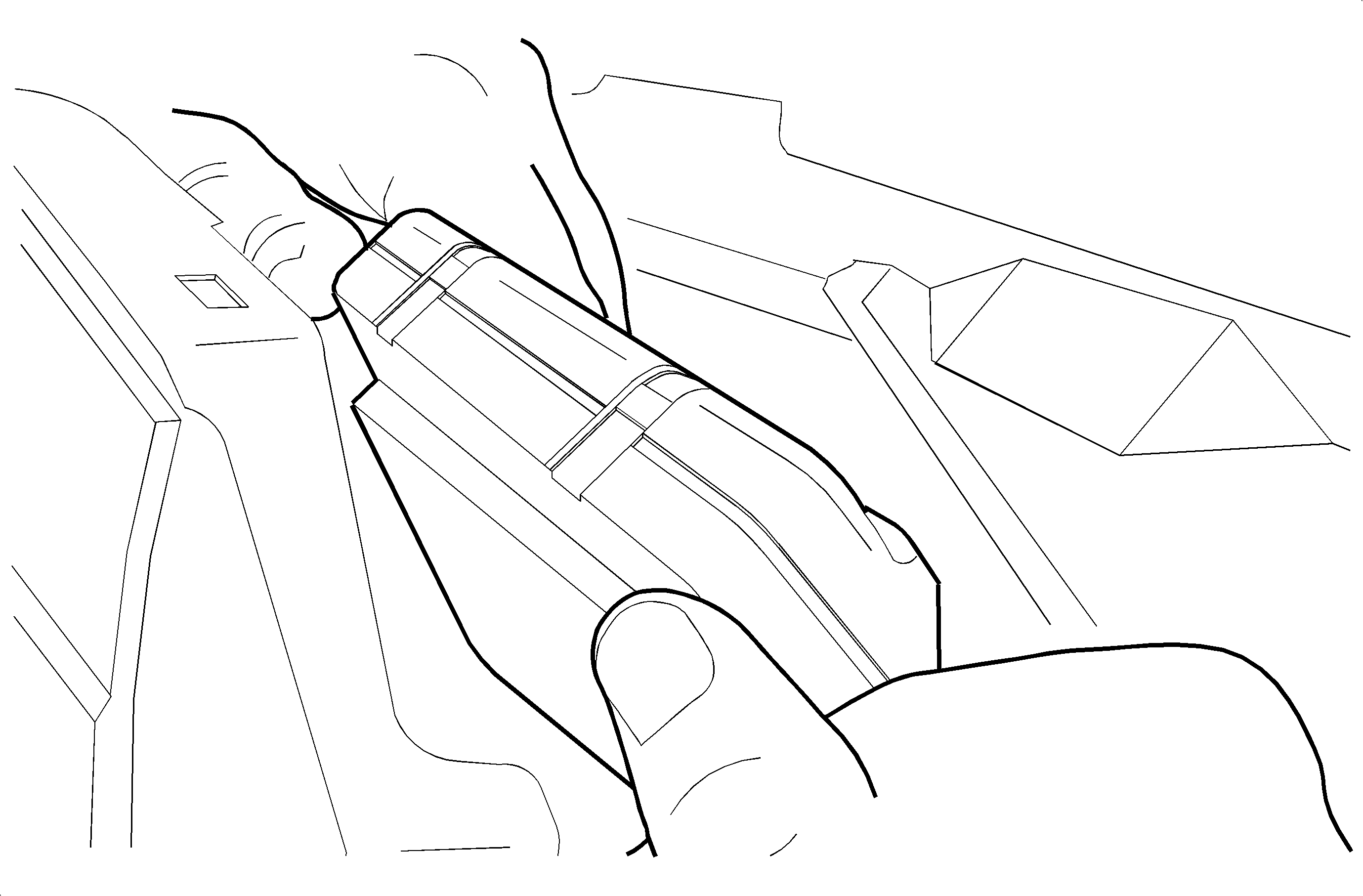
- Carefully tilt end of BCM opposite the connectors
upward from the cross-car beam.
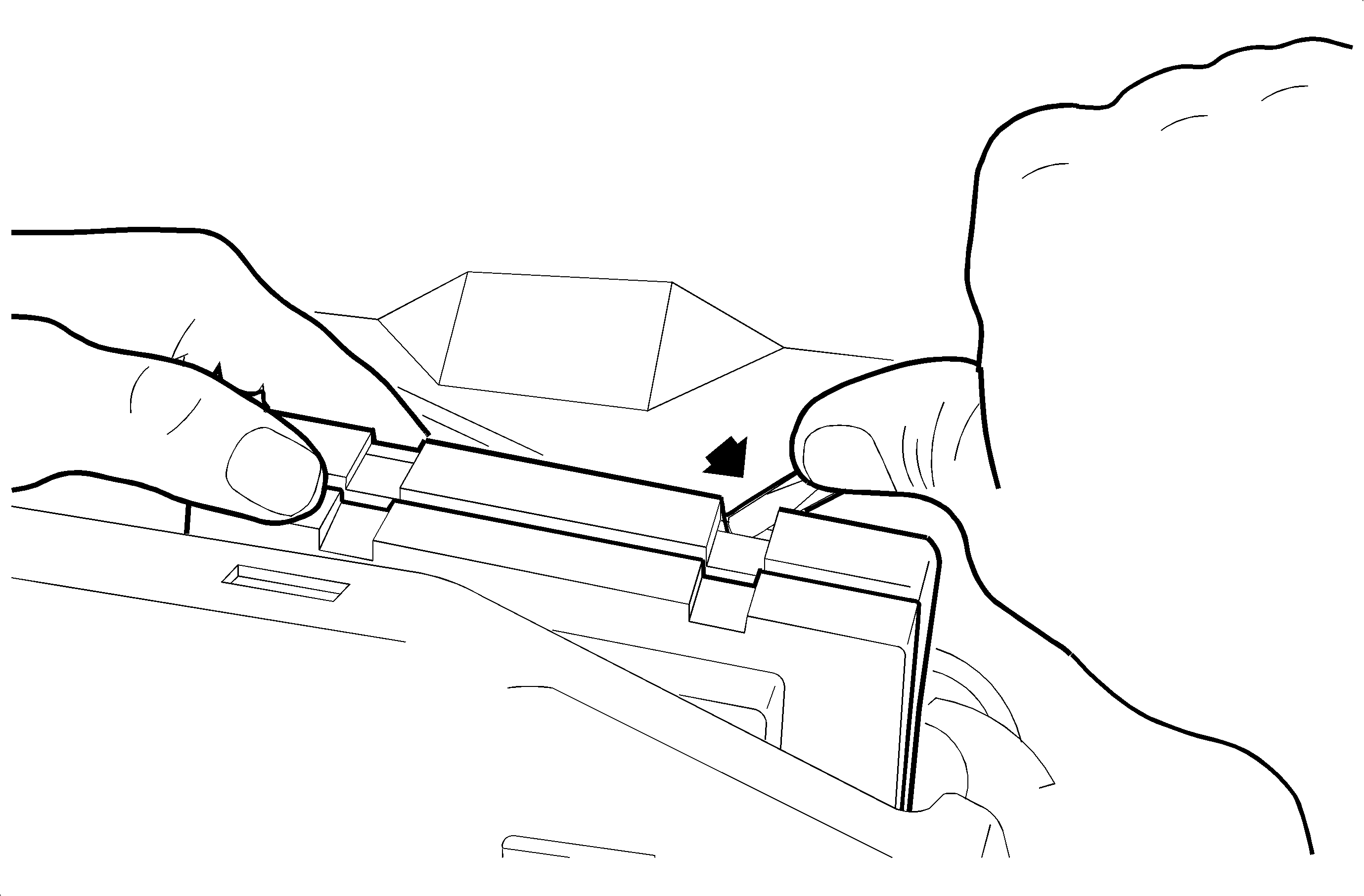
Notice: Do not touch the exposed electrical board.
- Using a small flat blade screwdriver, disengage locking tabs on BCM cover and
open cover.
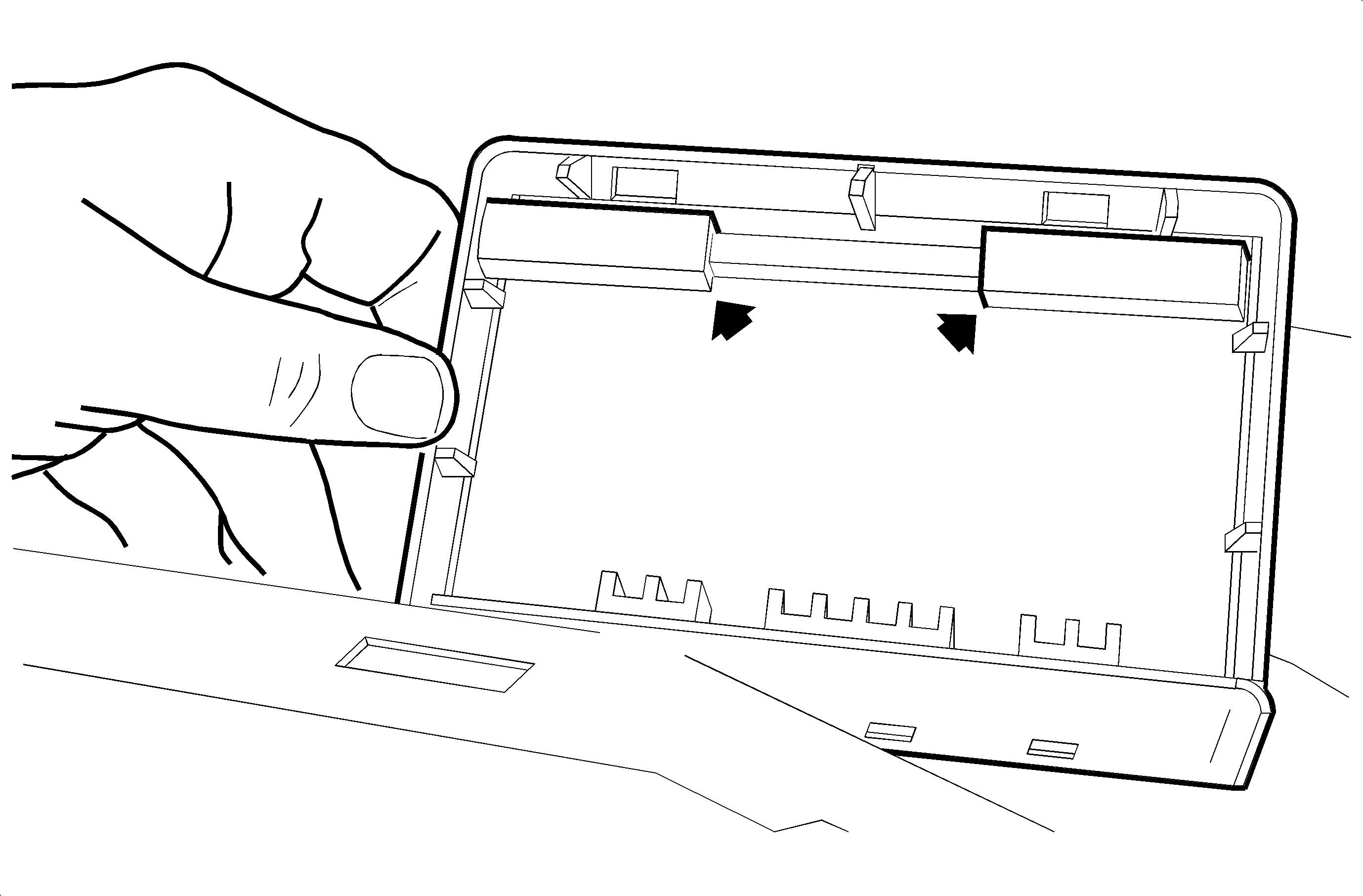
- Attach two foam pieces (P/N 21160169) to BCM
cover, positioning as shown in illustration.
- Close cover on BCM, ensuring that locking tabs are engaged.
Notice: Alignment tabs must be engaged before contact is made between adhesive and the
BCM mounting surface.
- Align and engage cross-car beam location with BCM alignment tabs located under
BCM connector body.
- Firmly press BCM into place on cross-car beam.
- Install upper trim panel.
| 10.1. | Ensure hook-and-loop fasteners on upper trim panel are correctly inserted. |
| 10.2. | Position upper trim panel on retainer assembly. |
| 10.3. | Align tabs on sides of upper trim panel with openings in windshield garnish
molding. |
| 10.4. | Align clips and clip location and firmly snap into place. |
| 10.5. | Install screws on underside of upper trim panel on passenger's side of
vehicle. |
Tighten
Tighten the Upper Trim Panel-to-I/P Screws 6 N·m (53 lb in)
- Enable the SIR system.
| 11.1. | Connect passenger (YEL 2-way) connector. |
| 11.2. | Attach connector clip to metal brace near HVAC fan. |
| 11.3. | Connect driver (YEL 2-way) connector and clip
to steering column brace. |
| 11.4. | Install AIR BAG fuse in IPFB. |
| 11.5. | Turn ignition On and verify AIR BAG telltale operates properly. |
Parts Information
21160169 - SEAL-FRT S/D
Warranty Information
To receive credit for this repair during the warranty coverage period, submit
a claim through the Saturn Dealer System for N4800 (Computer (Control), Body - R&R
or Replace), refer to the appropriate Electronic Labor Time Guide for the correct
Time.
