Info - Service Procedure for Replacement of Resonator and Intermediate Pipe

| Subject: | Service Procedure for Replacement of Resonator and Intermediate Pipe |
| Models: | 1998-2000 Saturn S-Series Vehicles |
| 2001 Saturn SC2 Coupe |
| with 1.9L Dual Overhead Cam (DOHC) Four-Cylinder Engine (VIN 7 - RPO LL0) |
| Attention: | Fixed Operations Manager and Technician |
Model Year | Model | VIN Breakpoint |
|---|---|---|
1998-2000 | S-Series (All) | Built After and Including VIN WZ217016 |
2001 | SC2 Coupe Only | Built Prior To and Including VIN 1Z118280 |
Purpose
The original service resonator with intermediate pipe assembly is no longer available for the models listed above. This bulletin contains new service procedures to replace:
- Intermediate pipe only
- Both resonator and intermediate pipe
Important: Refer to bulletin 00-T-78 to replace the resonator only.
Service Procedure for Replacing Only the Intermediate Pipe
Removal
- Raise vehicle squarely on a lift.
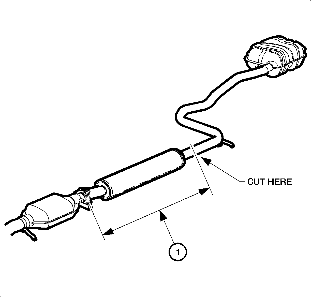
- Measure and mark intermediate pipe at location shown in illustration at a distance of 86 cm (34 in.) behind gasket surface of catalytic converter flange.
- Using chain cutter tool SA9168NE , or equivalent, cut intermediate pipe at previously marked location.
- Using chain cutter tool SA9168NE , or equivalent, cut intermediate pipe in front of the rear suspension. Locate center (1) of the approximately 100 mm (4 inch) long straight section, mark the pipe, and make cut.
- Disengage rubber isolator from hanger rod on intermediate pipe and remove pipe.

Caution: To avoid any vehicle damage, serious personal injury or death when major components are removed from the vehicle and the vehicle is supported by a hoist, support the vehicle with jack stands at the opposite end from which the components are being removed.
Notice: Perform the following steps before beginning any vehicle lifting or
jacking procedure:
• Remove or secure all of the vehicle's contents in order to avoid any shifting
or any movement that may occur during the vehicle lifting or jacking procedure. • The lifting or jacking equipment weight rating must meet or exceed the
weight of the vehicle and any vehicle contents. • The lifting or jacking equipment must meet the operational standards of
the lifting or jacking equipment's manufacturer. • Perform the vehicle lifting or jacking procedure on a clean, hard, dry,
level surface. • Perform the vehicle lifting or jacking procedure only at the identified
lift points. DO NOT allow the lifting or jacking equipment to contact any other vehicle
components.
Notice: Always use a chain cutter to cut the stainless steel exhaust system pipes. Use of other tools may result in damage to pipes.
Important: The replacement intermediate pipe should be used as a guide to precisely locate the cut location on the pipe section. Hold the replacement pipe to the existing section and mark the cut location BEFORE cutting or removing the old pipe.
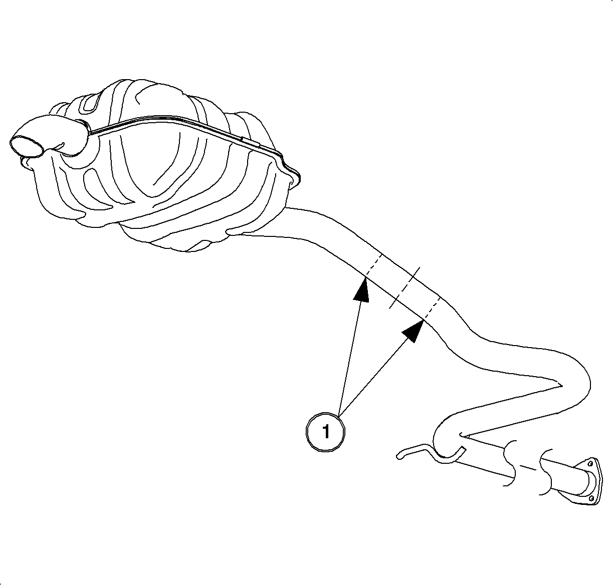
Important: If muffler is being replaced along with intermediate pipe, the intermediate pipe must be shortened at the outlet end so the muffler inlet can fit over it. Cut the intermediate pipe right behind the up-sized outlet end.
Installation
- Position service intermediate pipe under vehicle.
- Install pipe clamps on both ends of intermediate pipe.
- Slide intermediate pipe over remaining section of muffler inlet pipe and resonator outlet pipe.
- Install rubber isolator to hanger rod on intermediate pipe.
- Refer to illustration and position front pipe clamp 25 mm (1 in) from the end of intermediate pipe facing downward.
- Locate muffler clamp 25 mm (1 in) (2) from the end of the intermediate pipe and position clamp with U-bolt facing away from fuel tank.
- Align muffler and intermediate pipe to achieve proper clearances and then tighten clamps.
- Check exhaust system alignment and clearances. Rattle noises will occur if any of the clearances specified in step 7 are insufficient.
- Start engine and check for exhaust system leaks.
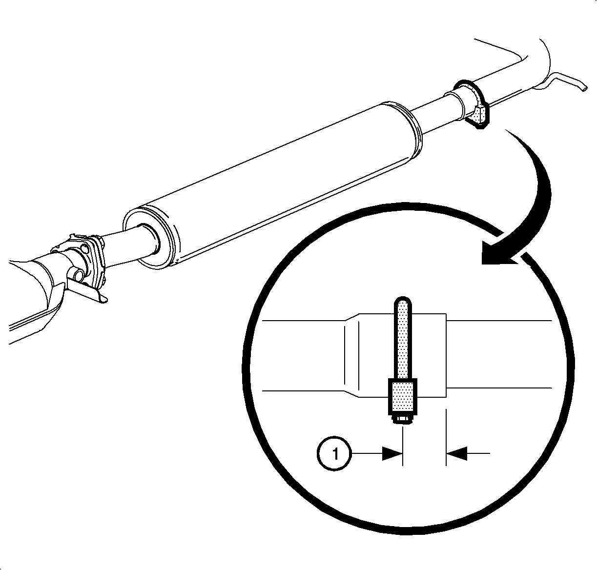
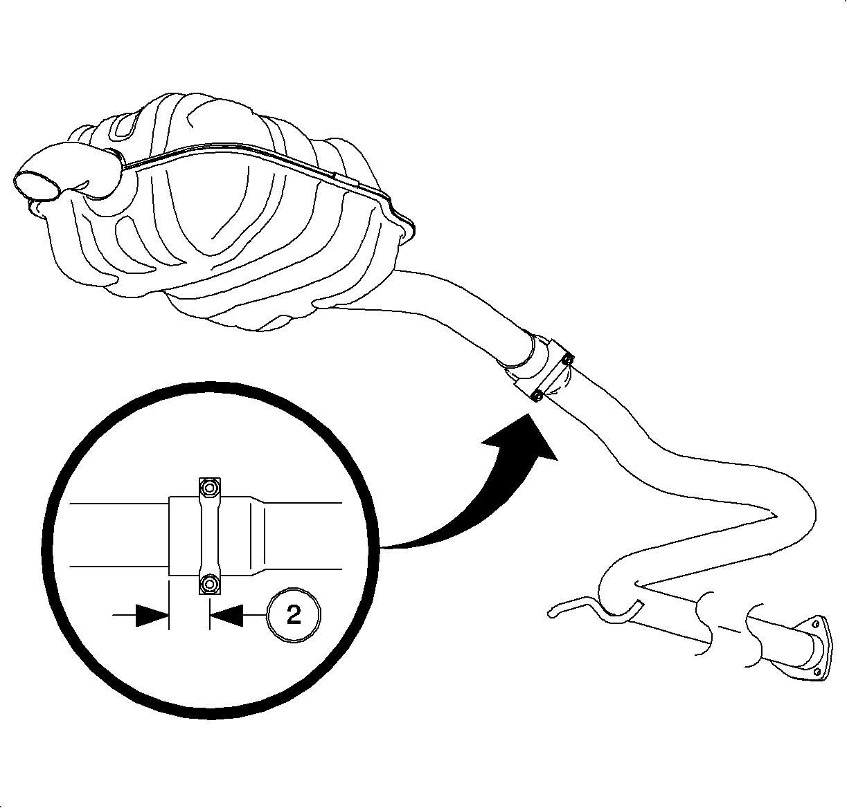
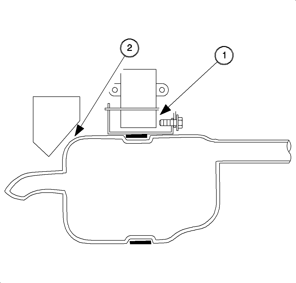
| • | Position muffler to ensure 19 mm (3/4 in) of clearance between rear of muffler and muffler ramp (2). If proper clearance cannot be obtained, intermediate pipe must be shortened at resonator joint. |
| • | Muffler hanger block should not contact hanger screw (1). If necessary, loosen muffler mounting strap, shift mounting strap forward to eliminate contact, and retighten. |
Tighten
Tighten muffler mounting strap fasteners to 22 N·m
(16 ft-lbs).
| • | Resonator should have at least 15 mm (9/16 in) clearance from heat shields. If necessary, bend heat shields away in any areas with insufficient clearance. |
| • | Tighten exhaust pipe clamp nuts. |
Tighten
Tighten exhaust pipe clamp nuts to 41 N·m
(30 ft-lbs).
Service Procedure for Replacing Both Resonator and Intermediate Pipe
- Mark SOHC service intermediate pipe 864 mm (34 in) behind gasket surface of catalytic converter.
- Using chain cutter tool SA9168NE , or equivalent, cut intermediate pipe at marked location. Discard front section of pipe.
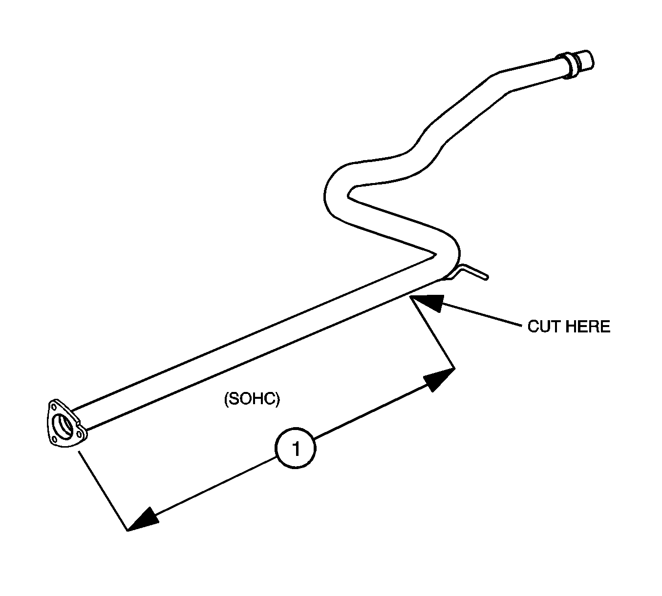
Important: The DOHC service intermediate pipe will not fit with the service resonator. If both pieces need replacement, use a SOHC intermediate pipe, P/N 21013145, and cut off the front section so it will fit into the resonator outlet.
Notice: Always use a chain cutter to cut the stainless steel exhaust system pipes. Use of other tools may result in damage to pipes.
Removal
- Raise vehicle squarely on a lift.
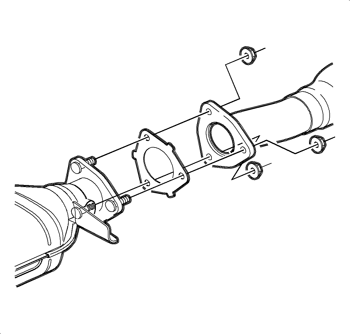
- Remove nuts at the outlet of the catalytic converter to intermediate pipe.
- Remove catalytic converter gasket and discard.
- Using chain cutter tool SA9168NE , or equivalent, cut intermediate pipe in front of the rear suspension. Locate center (1) of the approximately 100 mm (4 inch) long straight section, mark the pipe, and make cut.
- Disengage rubber isolator from hanger rod on intermediate pipe and remove pipe.

Caution: To avoid any vehicle damage, serious personal injury or death when major components are removed from the vehicle and the vehicle is supported by a hoist, support the vehicle with jack stands at the opposite end from which the components are being removed.
Notice: Perform the following steps before beginning any vehicle lifting or
jacking procedure:
• Remove or secure all of the vehicle's contents in order to avoid any shifting
or any movement that may occur during the vehicle lifting or jacking procedure. • The lifting or jacking equipment weight rating must meet or exceed the
weight of the vehicle and any vehicle contents. • The lifting or jacking equipment must meet the operational standards of
the lifting or jacking equipment's manufacturer. • Perform the vehicle lifting or jacking procedure on a clean, hard, dry,
level surface. • Perform the vehicle lifting or jacking procedure only at the identified
lift points. DO NOT allow the lifting or jacking equipment to contact any other vehicle
components.

Important: The replacement intermediate pipe should be used as a guide to precisely locate the cut location on the pipe section. Hold the replacement pipe to the existing section and mark the cut location BEFORE cutting or removing the old pipe.
Important: If muffler is being replaced along with intermediate pipe, the intermediate pipe must be shortened at the outlet end so the muffler inlet can fit over it. Cut the intermediate pipe right behind the up-sized outlet end.
Installation
- Position service intermediate pipe under vehicle.
- Slide intermediate pipe over remaining section of muffler inlet pipe.
- Install rubber isolator to hanger rod on intermediate pipe.
- Install pipe clamp over outlet end of resonator.
- Slide outlet end of resonator over front section of intermediate pipe.
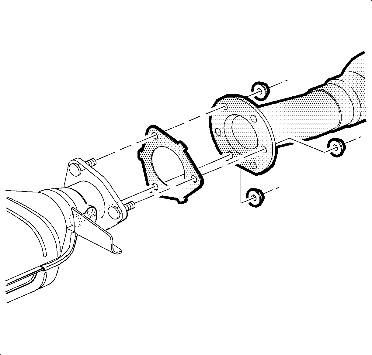
- Install new gasket at outlet end of catalytic converter.
- Install resonator to catalytic converter outlet flange and install nuts. Flat portion of resonator flange should face downward.
- Install pipe clamps at both ends of intermediate pipe.
- Refer to illustration and position front pipe clamp 25 mm (1 in) from the end of intermediate pipe facing downward.
- Locate muffler clamp 25 mm (1 in) (2) from the end of the intermediate pipe and position clamp with U-bolt facing away from fuel tank.
- Align muffler and intermediate pipe to achieve proper clearances and then tighten clamps.
- Check exhaust system alignment and clearances. Rattle noises will occur if any of the clearances specified in step 11 are insufficient.
- Start engine and check for exhaust system leaks.
Tighten
Tighten converter flange nuts to 25 N·m
(19 ft-lbs).


| • | Position muffler to ensure 19 mm (3/4 in) of clearance between rear of muffler and muffler ramp (2). If proper clearance cannot be obtained, intermediate pipe must be shortened at resonator joint. |
| • | Muffler hanger block should not contact hanger screw (1). If necessary, loosen muffler mounting strap, shift mounting strap forward to eliminate contact, and retighten. |
Tighten
Tighten muffler mounting strap fasteners to 22 N·m
(16 ft-lbs).
| • | Resonator should have at least 15 mm (9/16 in) clearance from heat shields. If necessary, bend heat shields away in any areas with insufficient clearance. |
| • | Tighten exhaust pipe clamp nuts. |
Tighten
Tighten exhaust pipe clamp nuts to 41 N·m
(30 ft-lbs).
Parts Information
Part Number | Description |
|---|---|
21013457 | Resonator |
21012835 | Gasket - Catalytic Converter |
25517280 | Clamp - Exhaust Muffler (2 required) |
21013458 | DOHC Intermediate Pipe (use when replacing intermediate pipe only) |
21013145 | SOHC Intermediate Pipe (use when replacing both intermediate pipe and resonator) |
Claim Information
To receive credit for this repair during the warranty coverage period, submit a claim through the Saturn Dealer System for L2420 (Intermediate Pipe - Replace).
