Tools Required
J 39119 02 sensor wrench
Removal Procedure
- Disconnect the front 02 sensor from the connector at the side of the engine.
- remove front 02 sensor using J 39119 .
- Remove the coolant extension pipe and engine lift bracket bolt.
- Remove the oil level indicator and tube.
- Remove the upper exhaust manifold nuts to cylinder head.
- Raise the vehicle.
- Remove the front down pipe assembly. Refer to Exhaust Manifold Pipe Replacement .
- Remove the right hand splash shield.
- Loosen the accessory drive belt from the pulleys.
- Disconnect the electrical connector at the A/C compressor and pressure transducer.
- Remove the A/C compressor to A/C bracket bolts.
- Remove the A/C compressor and support it with the straps. Position the compressor away from the exhaust manifold assembly.
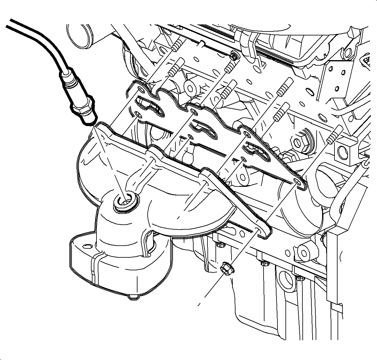
- Remove the exhaust manifold nuts.
- Remove the exhaust manifold assembly.
- Remove the exhaust manifold gasket.
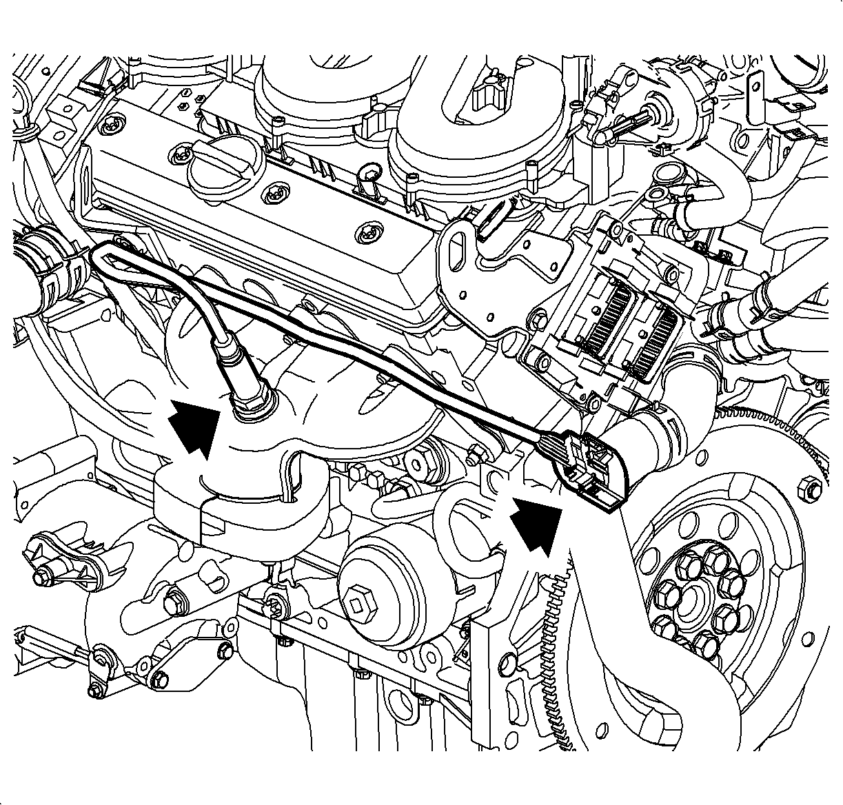
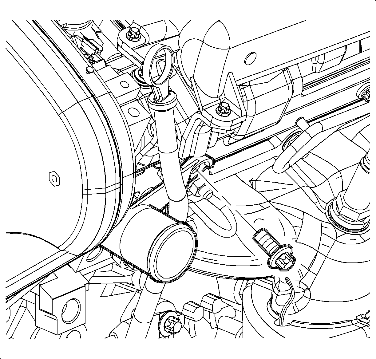
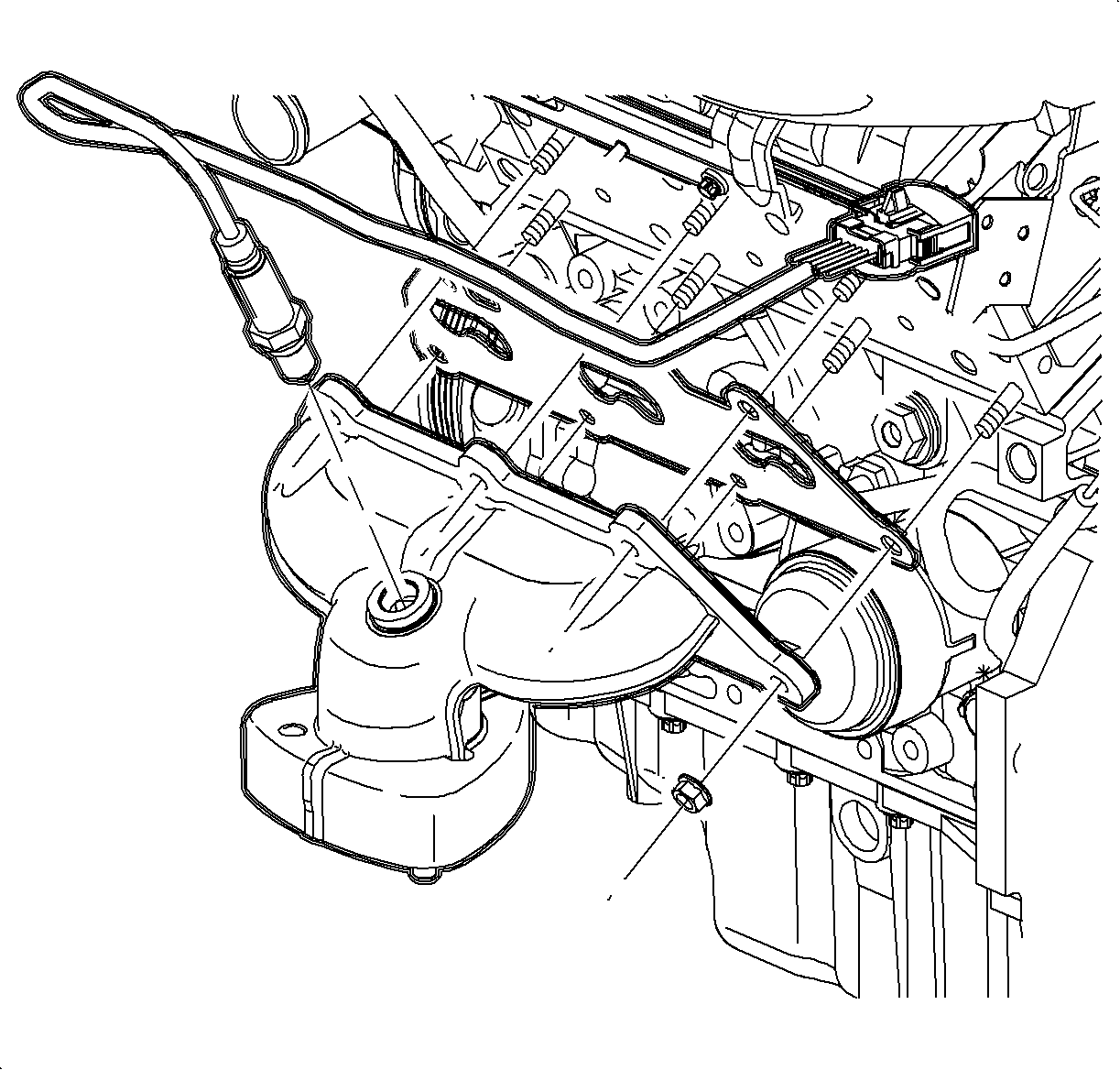
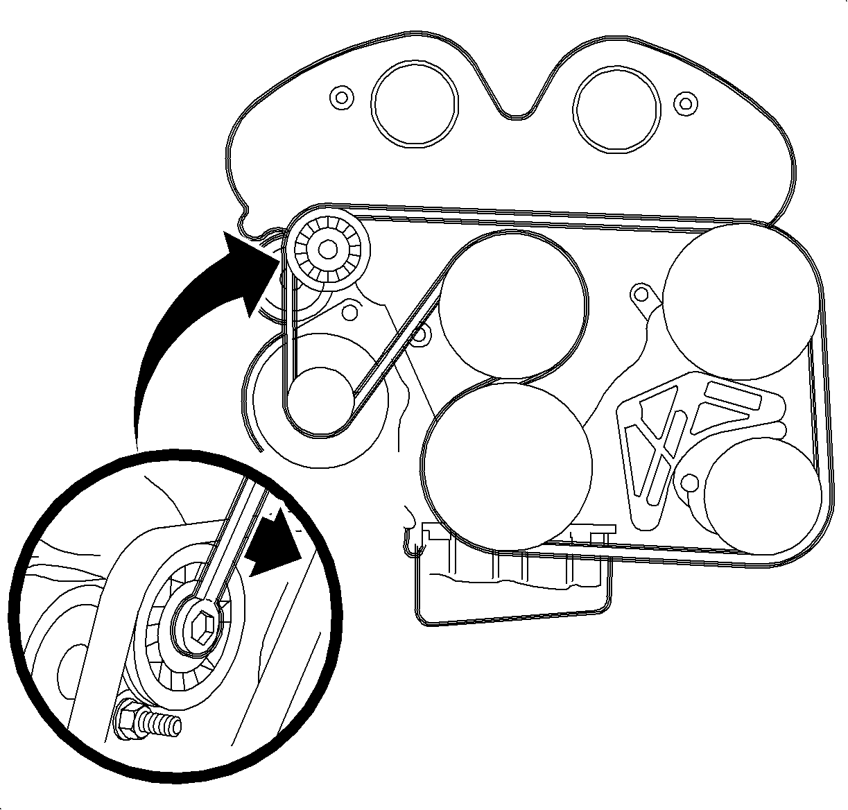
Important: Complete accessory drive belt (right hand mount) removal is not required. Only removal of the belt from the pulleys is required.
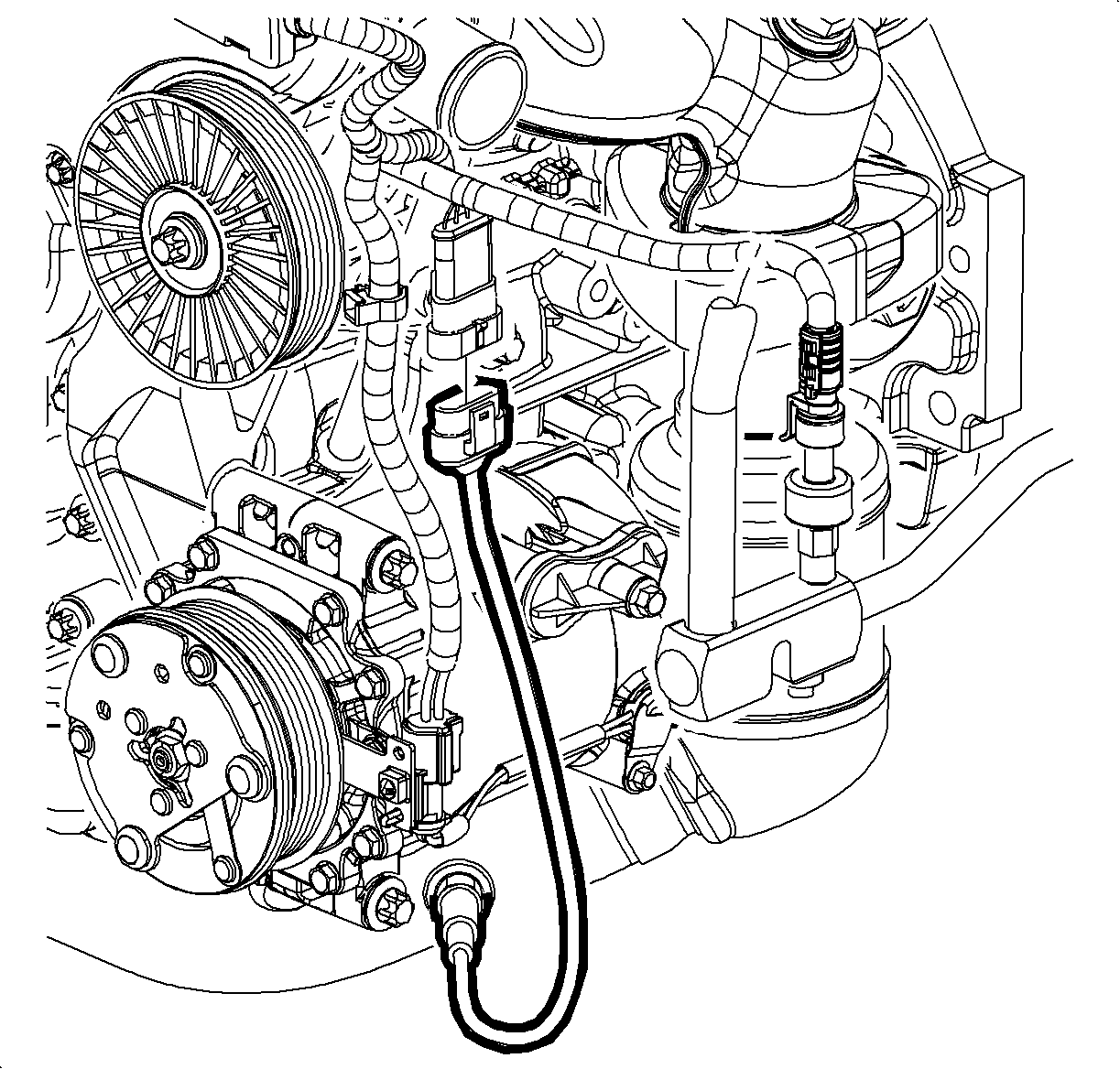
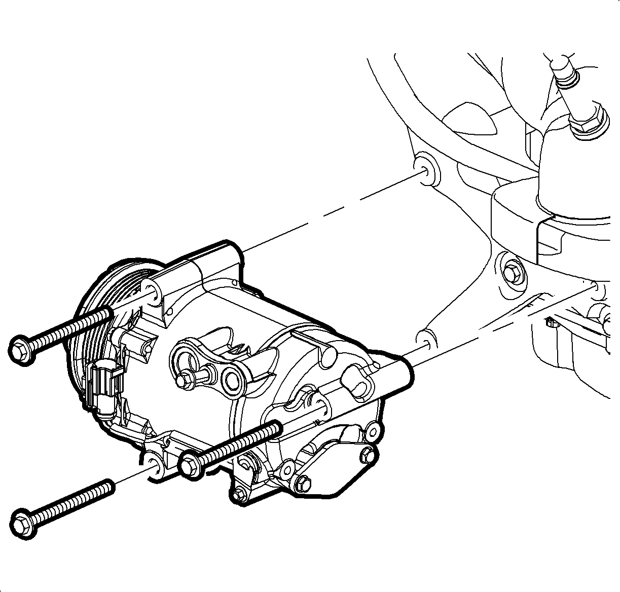
Important: The A/C system will not need to be evacuated. The A/C compressor and lines will remain connected throughout this procedure.
Installation Procedure
- Install a new manifold gasket on the cylinder head.
- Install the exhaust manifold.
- Install the exhaust manifold nuts.
- Install the front down pipe assembly refer to Exhaust Manifold Pipe Replacement .
- Install the A/C compressor to A/C bracket.
- Connect the electrical connector at the A/C compressor and pressure transducer.
- Install the accessory drive belt around the pulleys.
- Install the right hand splash shield.
- Lower the vehicle.
- Install the oil level indicator and tube.
- Install the 02 sensor into the exhaust manifold.
- Connect the 02 sensor electrical connector at the side of engine. Assure the connector is fully retained to the bracket

Tighten
Tighten the exhaust manifold nuts-L81 to 20 N·m (15 lb ft).
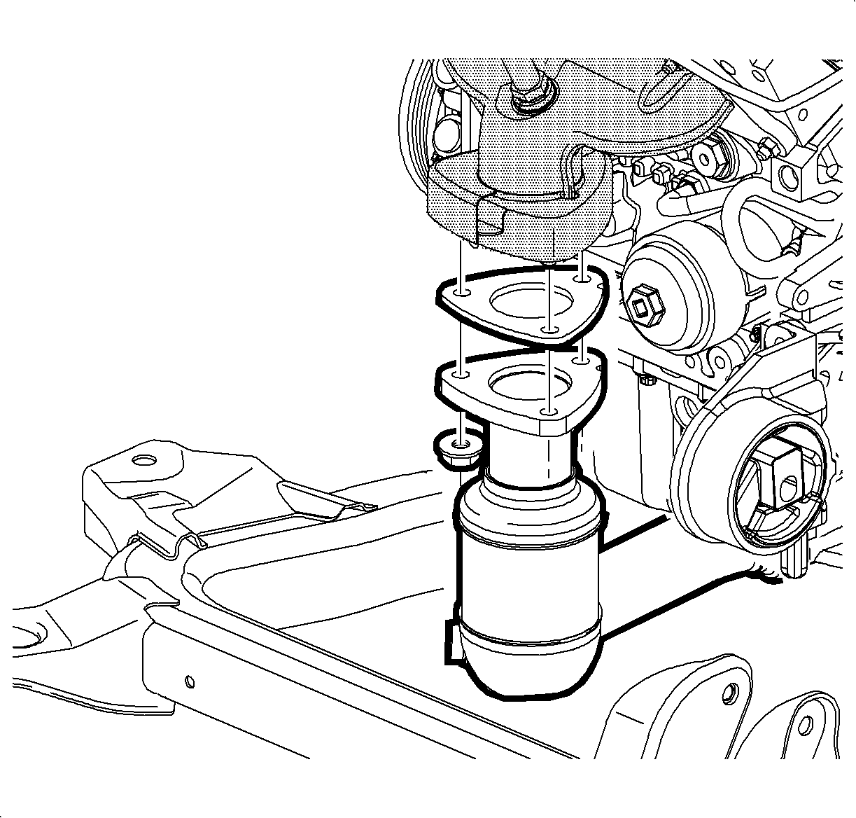
Tighten-
Tighten the A/C compressor-to-bracket bolt -L81 to 22 N·m(16 lb ft).

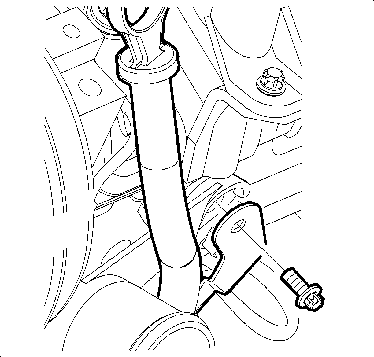
Tighten
Tighten the coolant extension pipe/engine lift bracket bolt -L81 to 20 N·m
(15 lb ft).

Important: Whenever the oxygen sensor is removed, coat the threads with nickel-based anti-seize compound such as Permatex® 77124, SA P/N 21485279 (or equivalent). Never use silicon products, silicon products will cause damage to oxygen sensor.
Tighten
Tighten the oxygen sensor-to-exhaust manifold pipe - L81 to 45 N·m
(33 lb ft).
