Removal Procedure
- Disconnect the negative battery cable.
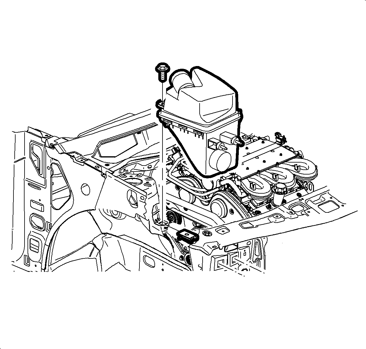
- Remove the air cleaner assembly. Refer to Air Cleaner Assembly Replacement in Engine Controls - 3.0L (L81).
- Raise and support the vehicle. Refer to Lifting and Jacking the Vehicle .
- Remove the right front wheel.
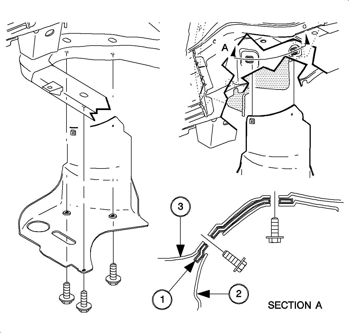
- Remove the splash shield push-pins.
- Remove the splash shield.
- Lower the vehicle.
- Install the Three Bar Engine Support Fixture 6 Cylinder (L81) B.
- Loosen the water pump and idler pulley bolts. The accessory drive belt tension provides resistance to enable loosening of the bolts. Do not remove the fastening bolt at this time.
- Remove the accessory drive belt using a 15 mm wrench to compress the tensioner.
- Remove the right engine mount to body mount.
- Remove the engine mount bracket from the engine.
- Remove the water pump pulley bolts.
- Remove the water pump pulley
- Remove the idler pulley bolt.
- Remove the idler pulley.
- Disconnect the electrical harness connectors located at the engine harness channel.
- Disconnect the electrical harness channel from the front cover and position away from the front cover assembly.
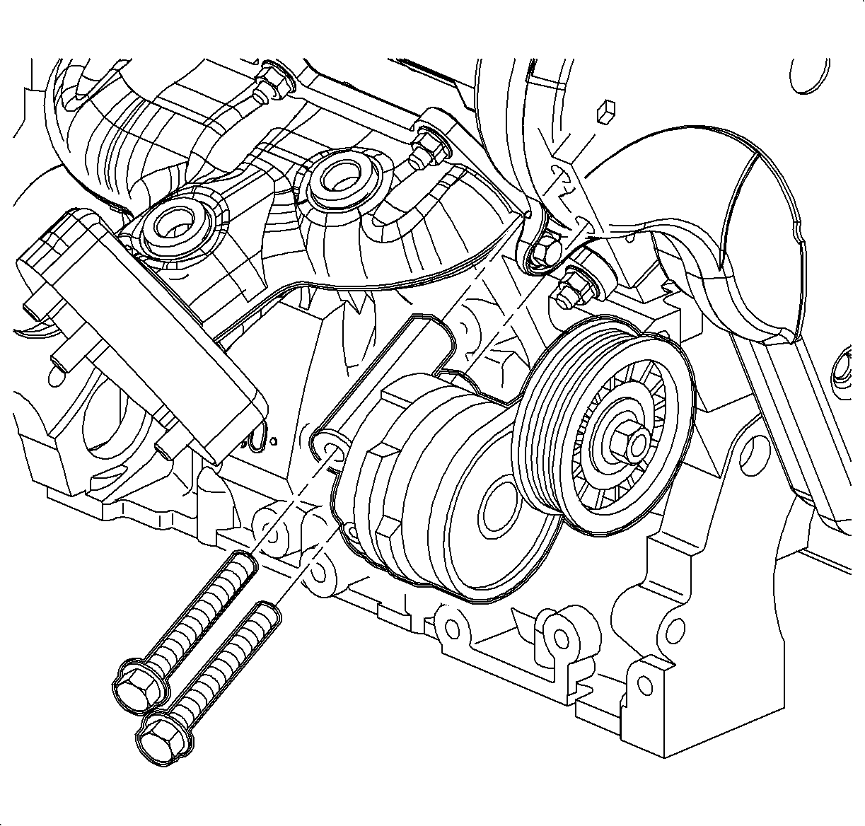
- Remove the accessory drive belt tensioner bolts.
- Remove the accessory drive belt tensioner.
- Remove the front timing belt cover bolts.
- Remove the front timing belt cover.
- Inspect the sealing strip on the outer edge of the front timing belt cover for cracks and/or tears. Replace if necessary.
Caution: Refer to Battery Disconnect Caution in the Preface section.
Important: The engine must be supported when the right hand engine mount is removed. If the floor jack is being used, the vehicle should not be lifted on a hoist.
Important: If raising the vehicle on a hoist, the Three Bar Engine Support must be used.
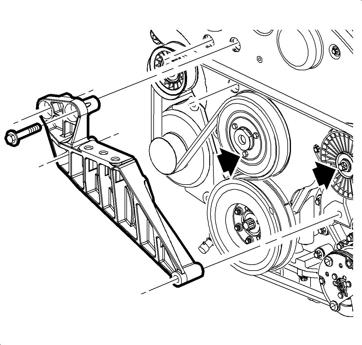
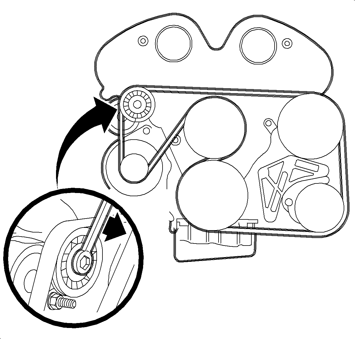
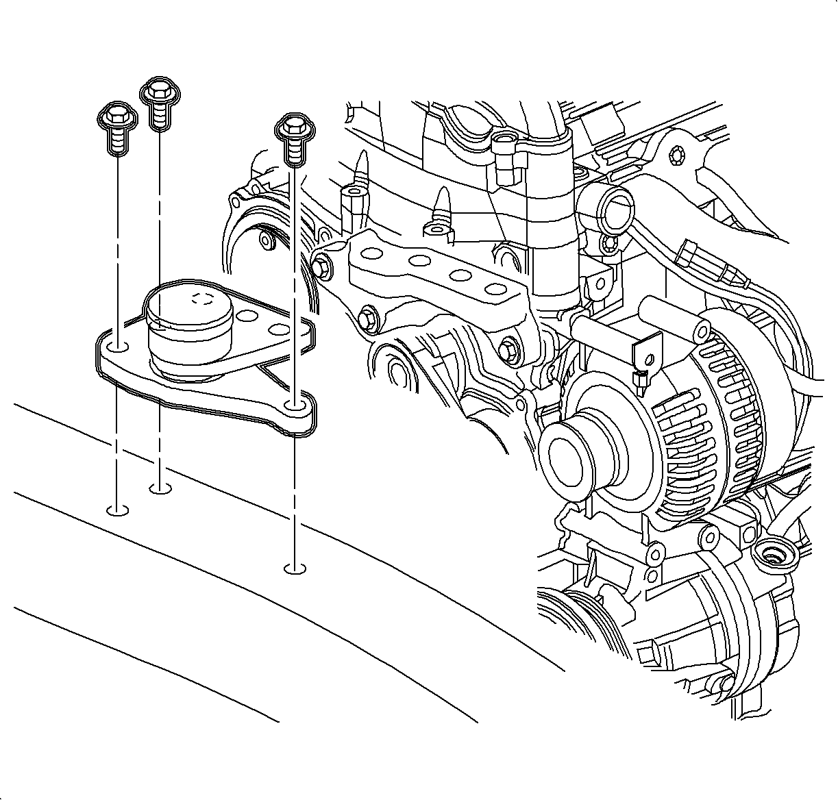
Important: Removal of the accessory drive belt requires the removal of the right front engine mount.

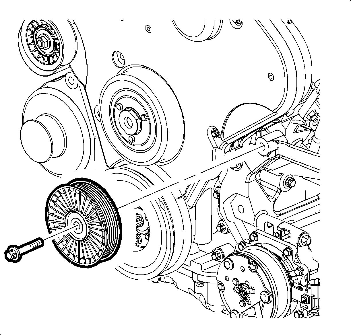
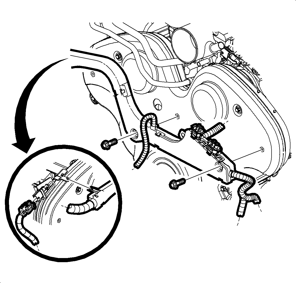
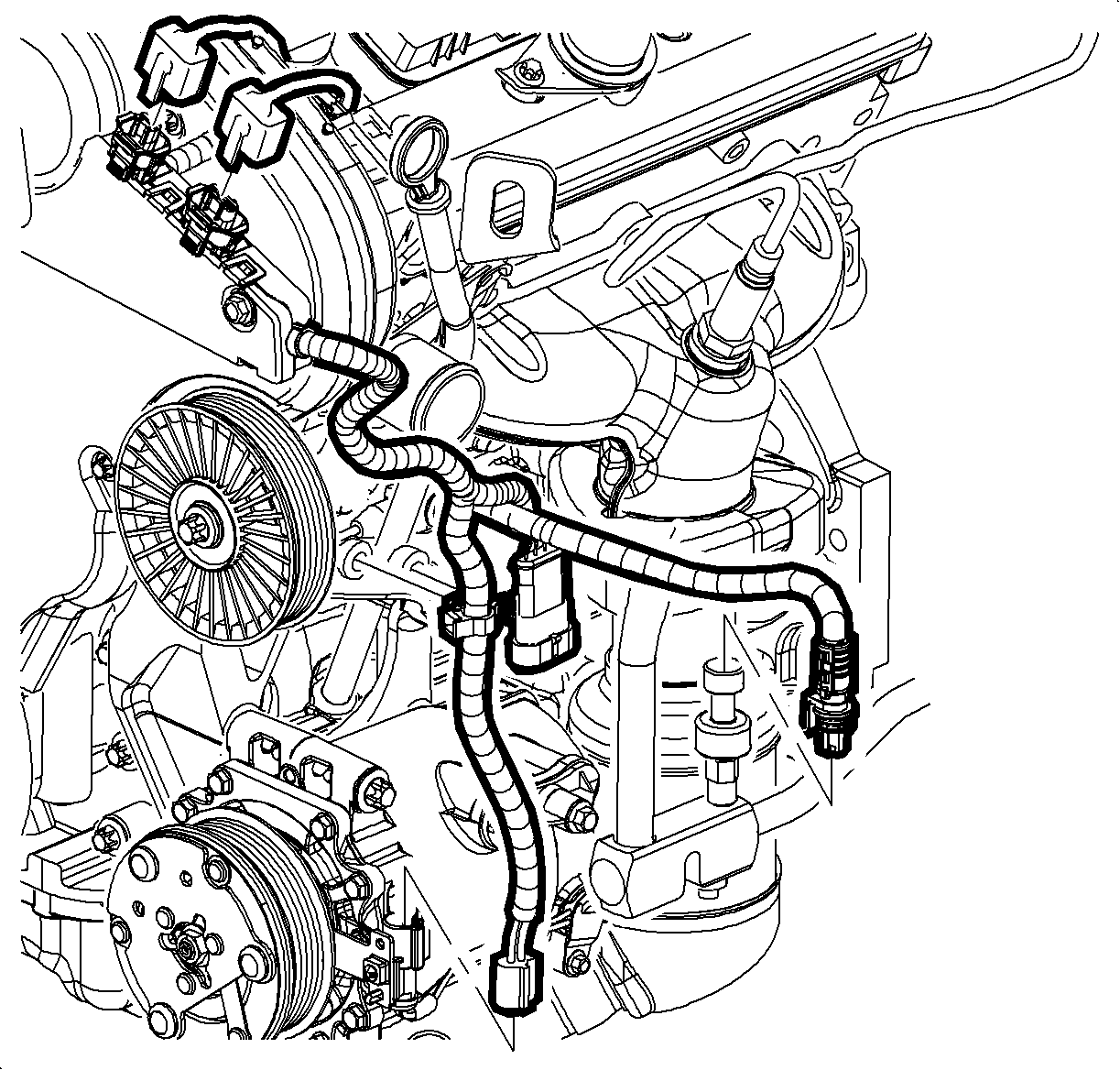
Important: Disconnecting the A/C pressure connector will allow additional slack so that the harness may be secured to the top of the engine.
Important: The engine harness channel has been disconnected and positioned away from the front cover assembly.
Installation Procedure
- Install the front timing belt cover.
- Install the front timing belt cover bolts.
- Install the accessory drive belt tensioner.
- Install the accessory drive belt tensioner bolts.
- Install the drive belt idler pulley.
- Install the drive belt idler pulley bolt.
- Snug the power idler pulley bolt. The bolts will be tightened to the proper specification when the serpentine drive belt is installed.
- Install the water pump pulley.
- Install the water pump pulley bolts. Snug the water pump pulley bolts. The bolts will be tightened to the proper specifications when the accessory drive belt is installed.
- Route the electrical harness into the engine harness channel and engage the connectors.
- Install the wiring harness channel to the front cover.
- Attach the wiring harness channel extension to the right lower side of the wiring harness channel.
- Install the accessory drive belt.
- Tighten the water pump pulley bolt.
- Tighten the drive belt idler pulley bolts.
- Install the engine mount bracket and tighten the bolts.
- Install engine mount-to-frame rail and engine mount bracket.
- Remove Three Bar Engine Support Fixture.
- Raise the vehicle.
- Install the splash shield.
- Install splash shield push pins.
- Install right front wheel and tire assembly.
- Lower the vehicle.
- Install air cleaner assembly. Refer to Air Cleaner Assembly Replacement .
- Connect negative battery cable.

Notice: Refer to Fastener Notice in the Preface section.
Tighten
Tighten the front timing belt cover bolt to 8 N·m
(71 lb in).
Tighten
Tighten the belt tensioner bolts to 40 N·m
(30 lb ft).


Notice: Be sure to properly route the electrical harness to prevent harness damage caused by the accessory drive belt.


Tighten
Tighten the water pump pulley bolt to 8 N·m
(71 lb in).
Tighten
Tighten the idler pulley bolt to 20 N·m
(15 lb ft).
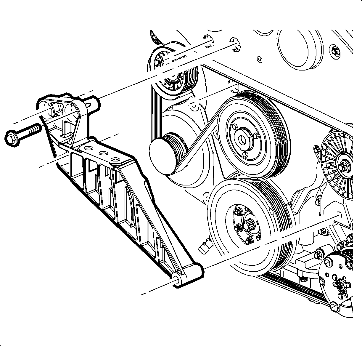
Tighten
Tighten the engine mount bracket bolts to 55 N·m
(41 lb ft).
Tighten
Tighten the engine mount-to- bracket bolt to 55 N·m
(41 lb ft).
Caution: Ensure that the vehicle is properly supported and squarely positioned. To help avoid personal injury when a vehicle is on a hoist, provide additional support for the vehicle on the opposite end from which the components are being removed.
Tighten
Tighten the wheel nuts to 125 N·m (92 lb ft).
Tighten
Tighten the battery terminal bolt to 17 N·m
(13 lb ft).
