Tools Required
| • | J 43649 Valve Spring Compressor. |
| • | J 44655 Camshaft Support Holder. |
| • | SA9102E-A Valve Seal Remover/Replacer. |
| • | SA9127E Gage Bar Set. |
| • | J 43653 Flywheel Holding Tool |
Removal Procedure
- Disconnect the negative battery cable.
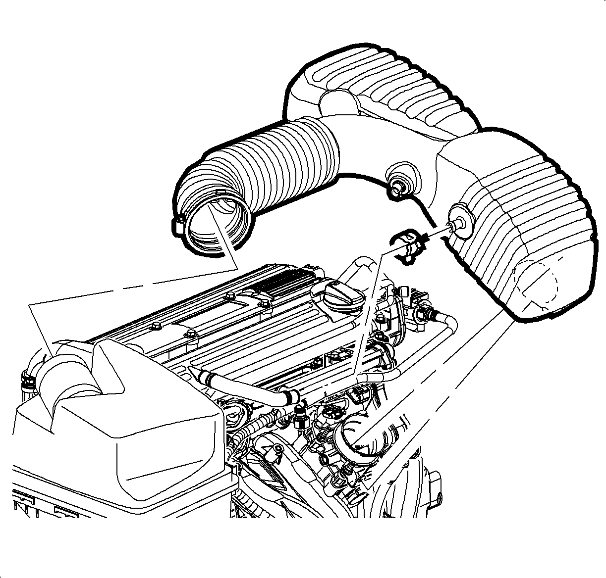
- Disconnect the intake air temperature.
- Loosen the clamp at air cleaner assembly.
- Remove the pushpin attachment from the outlet resonator/duct assembly to the support bracket.
- Loosen the clamp at the throttle body assembly
- Disconnect the PCV fresh air vent hose at the cam cover.
- Remove the outlet resonator/duct assembly.
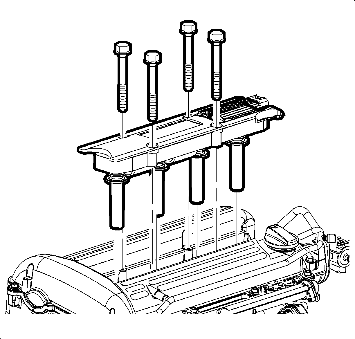
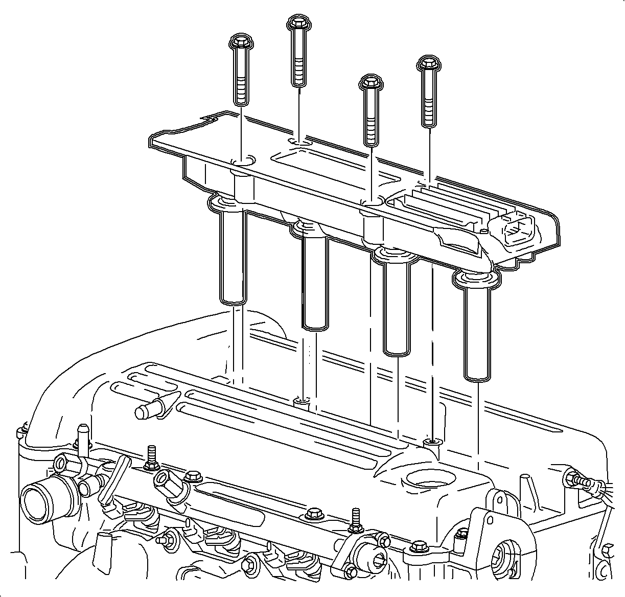
- Remove the ignition module assembly with the bolts.
- Disconnect the coolant degas bracket and the bolt at the back of the cylinder head.
- Disconnect the degas hose at the clamp at the cylinder head and position away from the cam cover assembly.
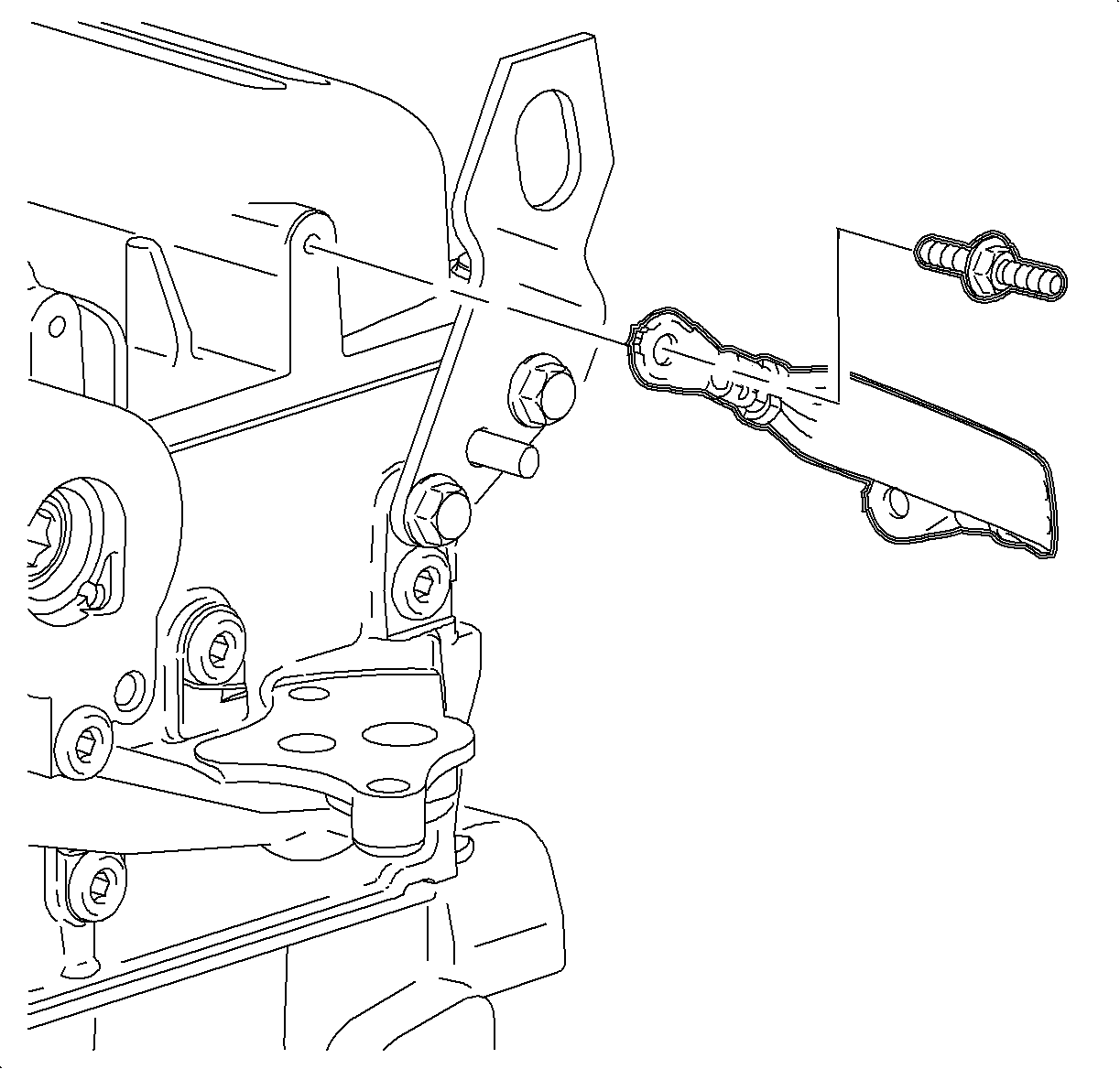
- Disconnect the ground strap at the rear of the cam cover assembly.
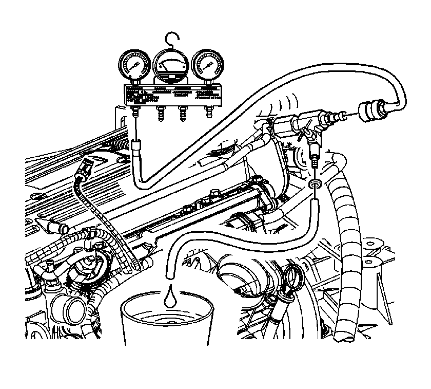
- Relieve the fuel system pressure. Refer to Fuel Pressure Relief
- Disconnect the Gage Bar Set SA9127E after pressure has been relieved.
- Disconnect fuel rail bracket and bolt at rear of the cam cover.
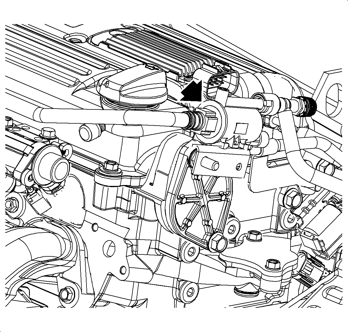
- While supporting the fuel rail assembly with an-open end wrench, loosen the transfer line fitting at the fuel rail.
- Position the fuel line away from the cam cover assembly.
- If equipped with a manual transmission, leave the transmission in first gear with the vehicle on the ground and the parking brake set.
- If equipped with an automatic transmission, remove the starter. Refer to Starter Motor Replacement in Engine Electrical.
- Install the J 43653 .
- Remove the cam cover assembly bolts.
- Remove the cam cover assembly.
- Remove the purge valve from power steering plate.
- Remove the power steering block off plate if the intake camshaft is being removed.
- Locate the No. 1 piston to approximately 60 degrees before top-dead-center (diamond shaped hole on intake camshaft sprocket at 12 o'clock position). Remove the spark plugs. This will ease rotation effort.
- Remove the upper timing chain guide.
- Remove the front camshaft caps
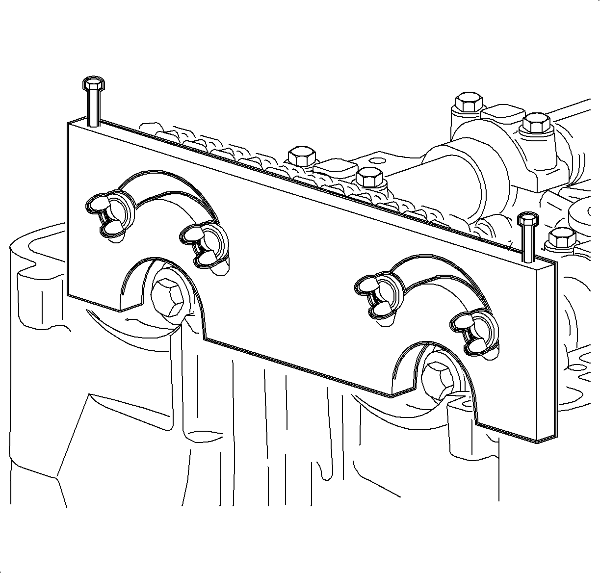
- Install the Camshaft Support Holding tool J 43655 through the sprocket holes from the timing chain side of the sprocket towards the rear of the engine.
- With the guide pin installed in the sprocket, align the guide pins into the slots on the support plate.
- Tighten the support plate-to-cylinder head.
- Install the wingnuts and tighten
- Hold each camshaft in place using a 24 mm open-end wrench and carefully remove the camshaft sprocket timing retaining bolts and washers. Discard the torque- to-yield (TTY) bolts.
- Slide the camshaft sprockets away from the camshafts.
- To release the spring tension on the camshaft, after the camshaft is disengaged from the sprocket, rotate the camshaft using a 24 mm wrench to a neutral position.
- Uniformly loosen and remove the remaining camshaft bearing cap bolts.
- Carefully pull the camshaft(s) straight up to avoid damaging the cylinder head thrust surfaces.
- Remove the rocker arms (followers).
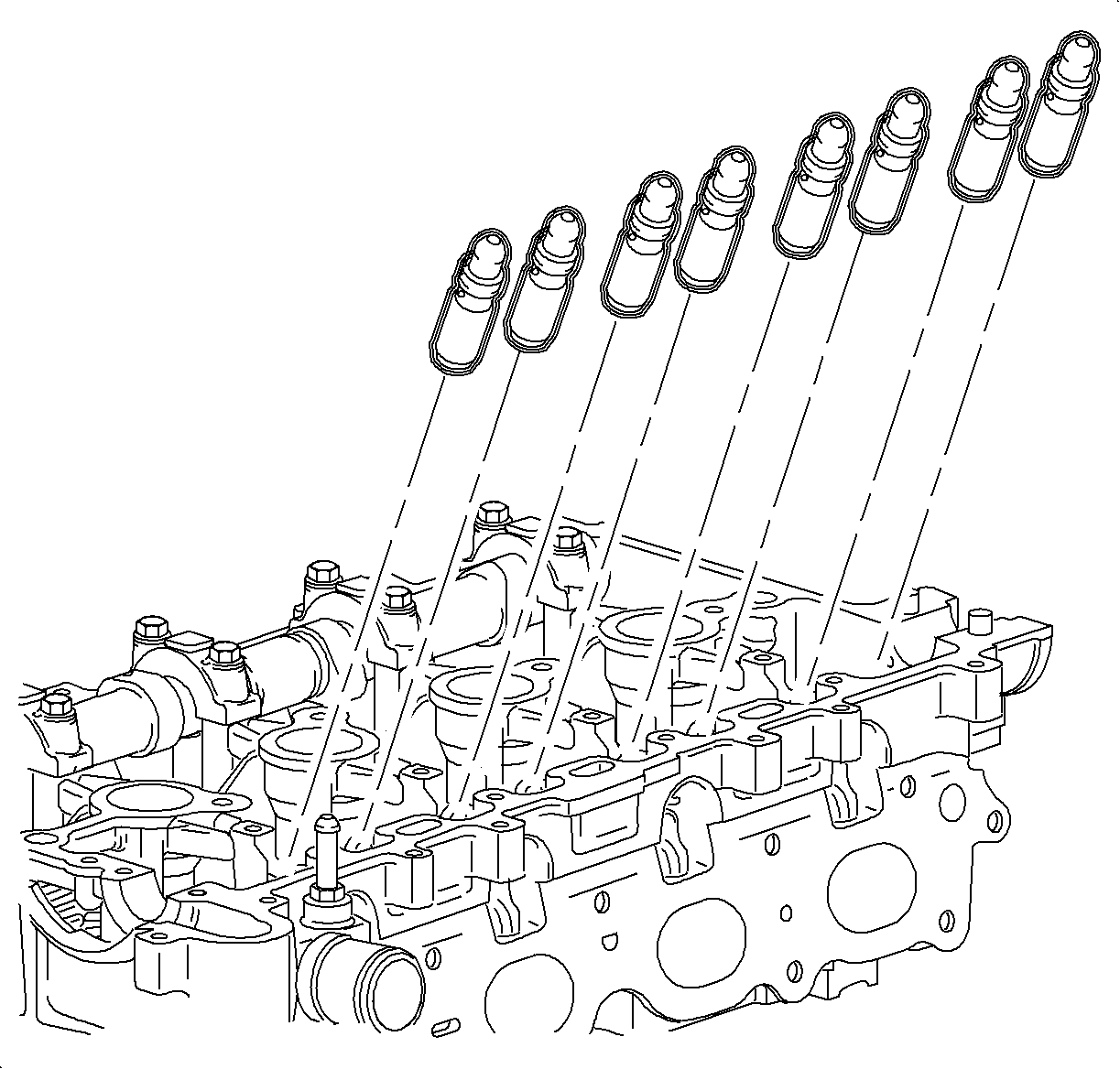
- Remove the latch adjusters.
- Install the Valve Spring Compressor J 43649 . Use the four cam cover bolts to mount the supports to the cylinder head. Thread the bolts into the cam cover holes.
- Install the spark plug adapter from the Gage Bar Set SA9127E in the respective cylinder.
- Pressurize the cylinder being serviced to 690 kPa (10 psi).
- Both the intake and the exhaust valves must be closed to allow pressure to build. Do not rotate the engine.
- Position compressor assembly over the valve spring to be removed and tighten down.
- Use a magnet to remove the valve retainers.
- Release the tension on the Valve Spring Compressor J 43649 tool.
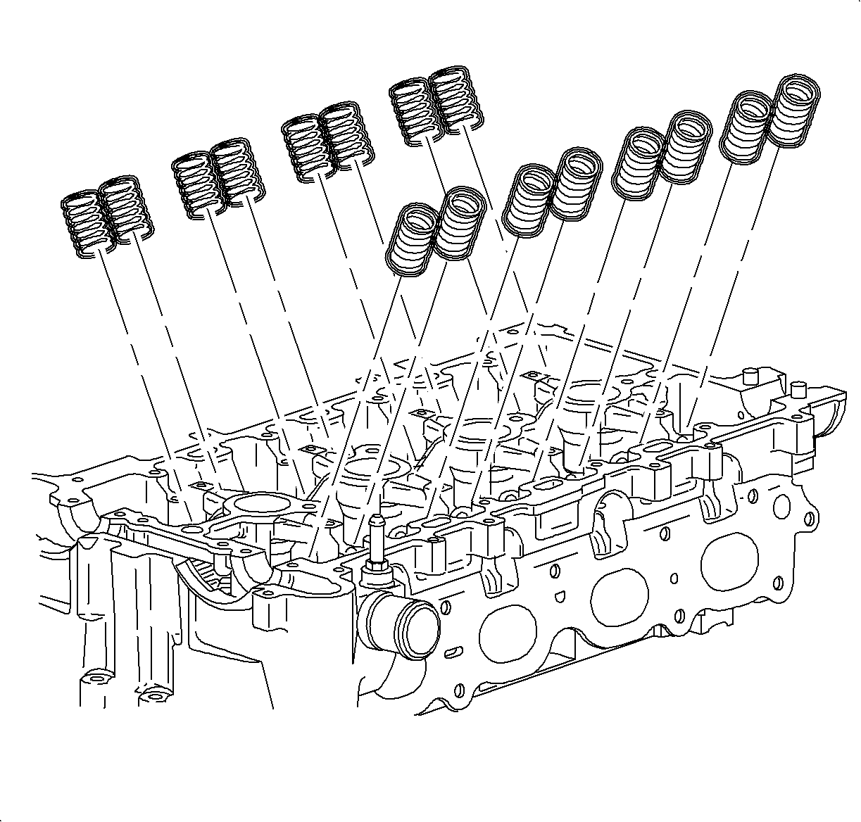
- Remove the valve spring and the spring.
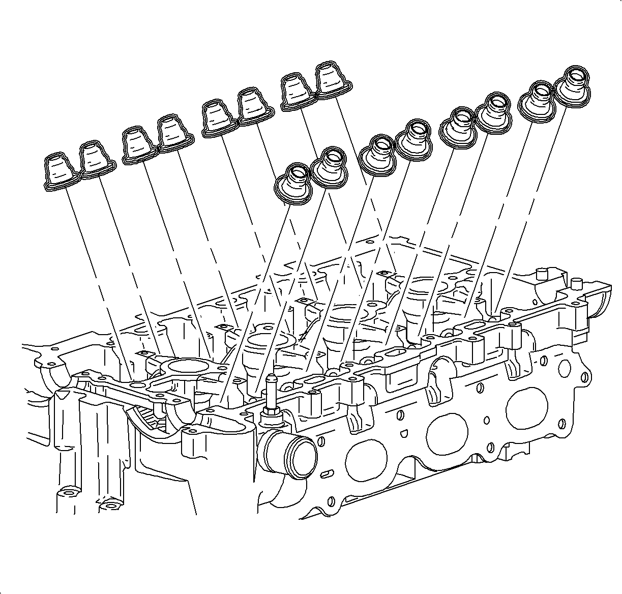
- Remove the valve seal using the Valve Seal Remover/Replace tool. SA9102E-A
- One cylinder must be serviced at a time to allow the cylinder to be pressurized. After assembly, steps 36 through 42 can be completed on other cylinders as necessary.
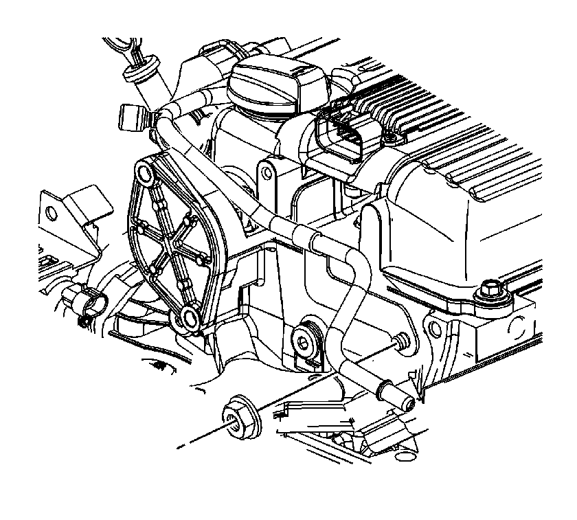
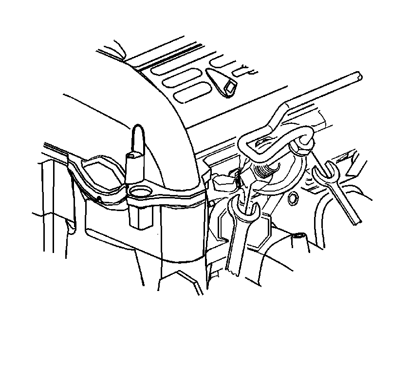
Caution: Whenever fuel line fittings are loosened or disconnected, wrap a shop cloth around the fitting to collect fuel. Place the cloth in an approved container.
Notice: An open-end wrench must be used to support the fuel line to rail connection during loosening/tightening to avoid damaging the fuel rail assembly.
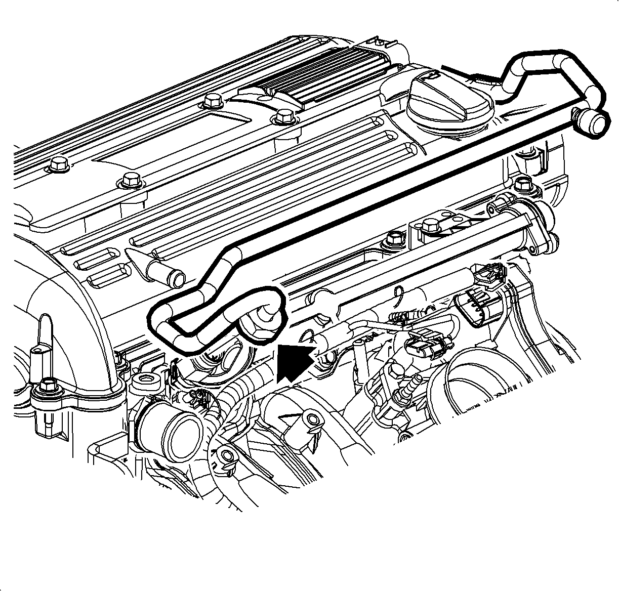
Important: Prevent the crankshaft from rotating clockwise or counterclockwise before using compressed air in the cylinder. Rotation of the crankshaft may cause damage to J 43653 .
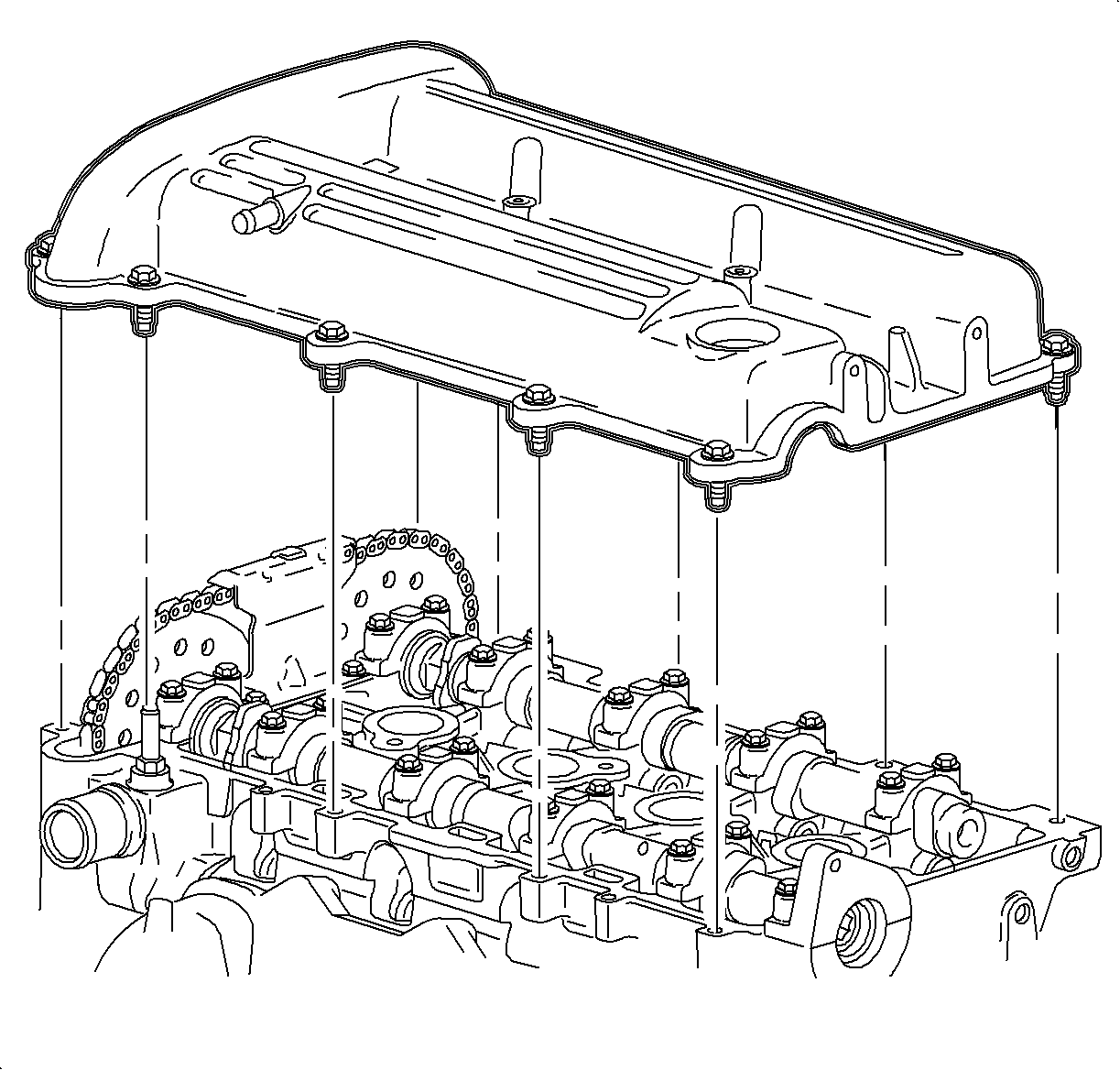
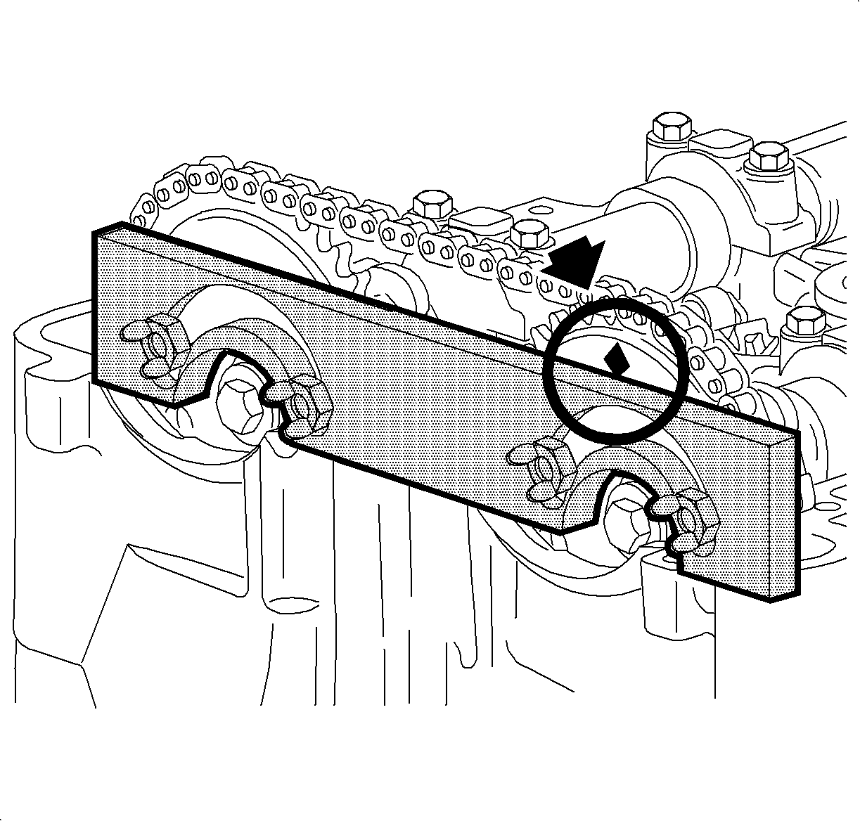
Notice: To avoid valve piston contact, No. 1 cylinder piston must be positioned at approximately 60 degrees before-top dead center (BTDC). Pistons are properly positioned when the diamond shaped hole on the intake camshaft sprocket is located at 12 o'clock.
Important: To rotate the camshaft(s), use a 24 mm open-end wrench on the camshaft flats. Camshaft(s) should be rotated in a clockwise direction only. (facing the camshaft sprockets from the passenger side of the vehicle).
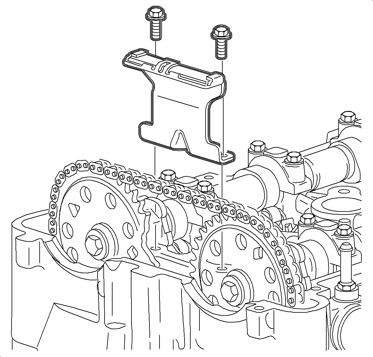
Important: When removing the guide bolts do not drop down into the front cover.

Notice: During the camshaft removal procedure, the pistons are locked in position by the J43655 camshaft support holding tool. Do not rotate the engine crankshaft or tool damage and timing reset will be required. Camshafts can be rotated only after the #1 piston is at 60° BTDC and the sprocket has been disengaged from the camshaft.
Important: Lubricate the sprocket pins with clean motor oil. These will allow sprockets to easily slide on the sprocket pins.
Tighten
Tighten the support plate-to-cylinder head: 10 N m (89 lb in)
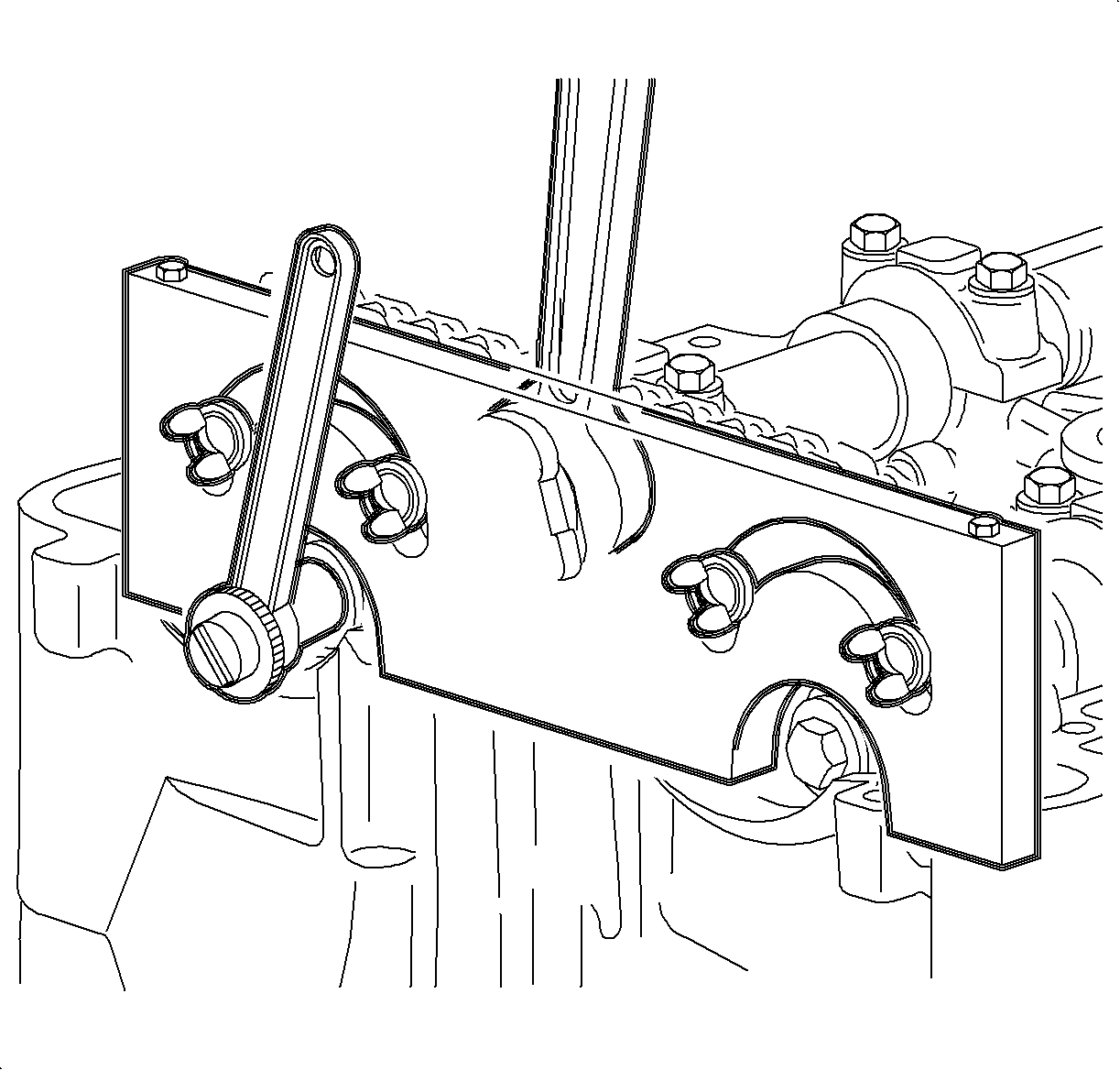
Important: When sliding the timing chain and sprockets onto guide pins, be sure the timing chain is positioned properly on adjustable or fixed guide or guide damage will occur. Care should be taken when removing the camshaft sprockets from the camshafts.
Important: Camshafts are spring loaded and may rotate. Care should be taken until all spring tension is removed from the camshaft.
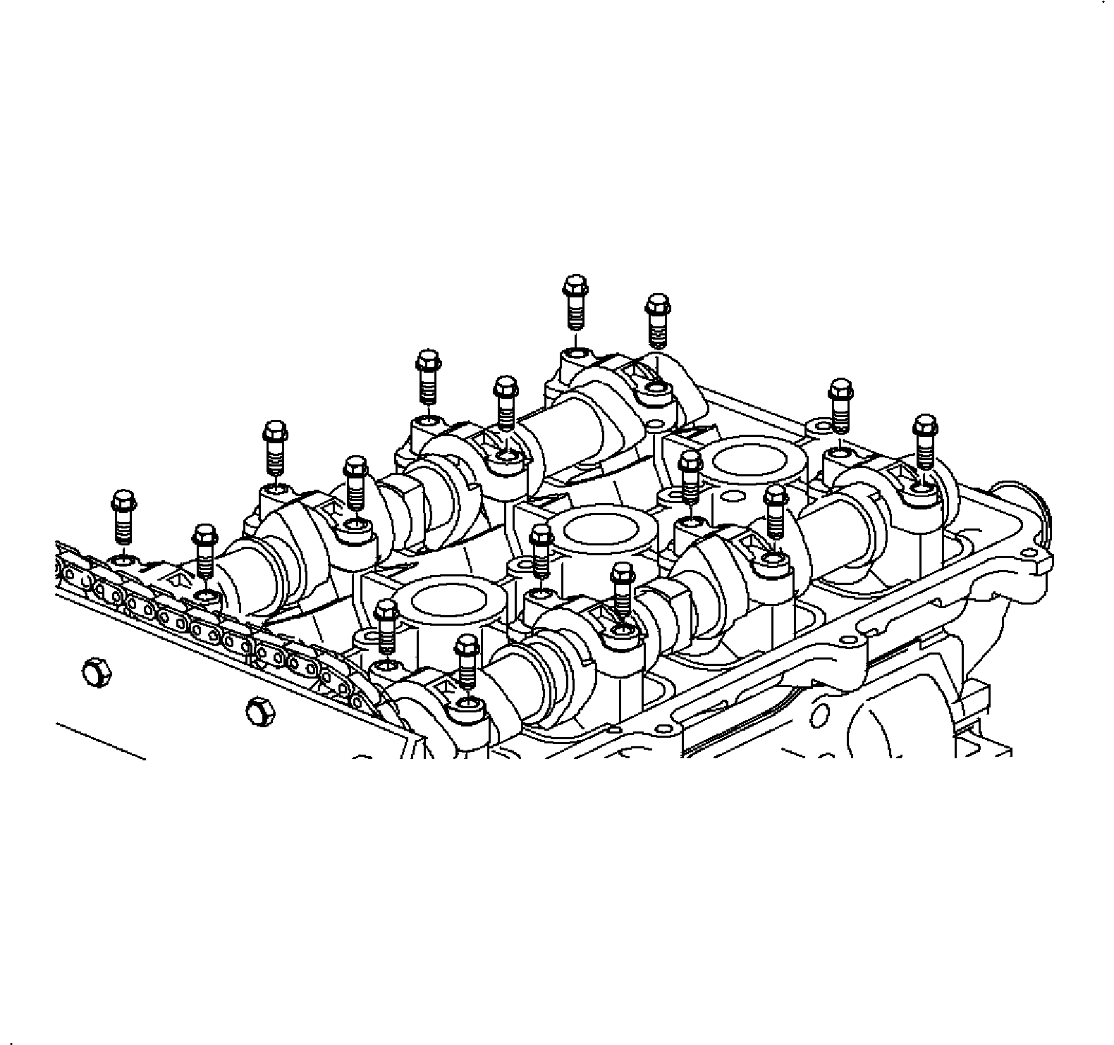
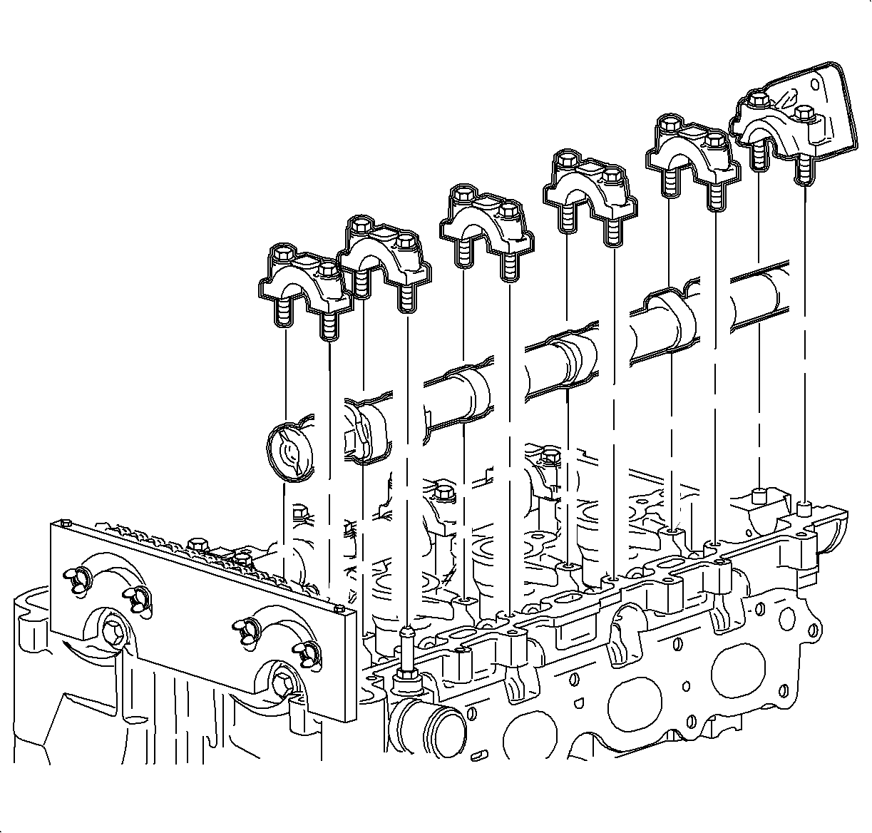
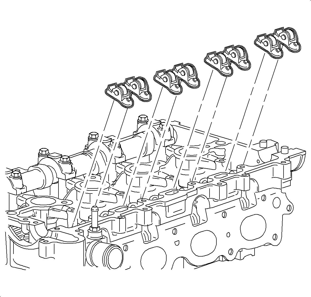
Important: When servicing the cylinder head components, components should be kept in order to assure proper assembly.
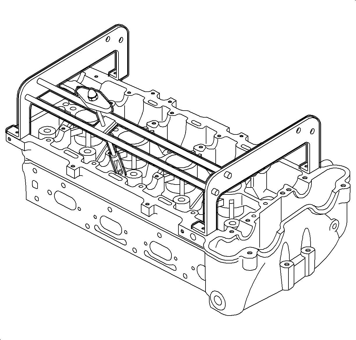
Notice: During the camshaft removal procedure, the pistons are locked in position by the J43655 camshaft support holding tool. Do not rotate the engine crankshaft or tool damage and timing reset will be required. Camshafts can be rotated only after the #1 piston is at 60° BTDC and the sprocket has been disengaged from the camshaft.
Tighten
Tighten the cam cover bolts-to-hold the valve spring compressor: 10 N m (89 lb in).
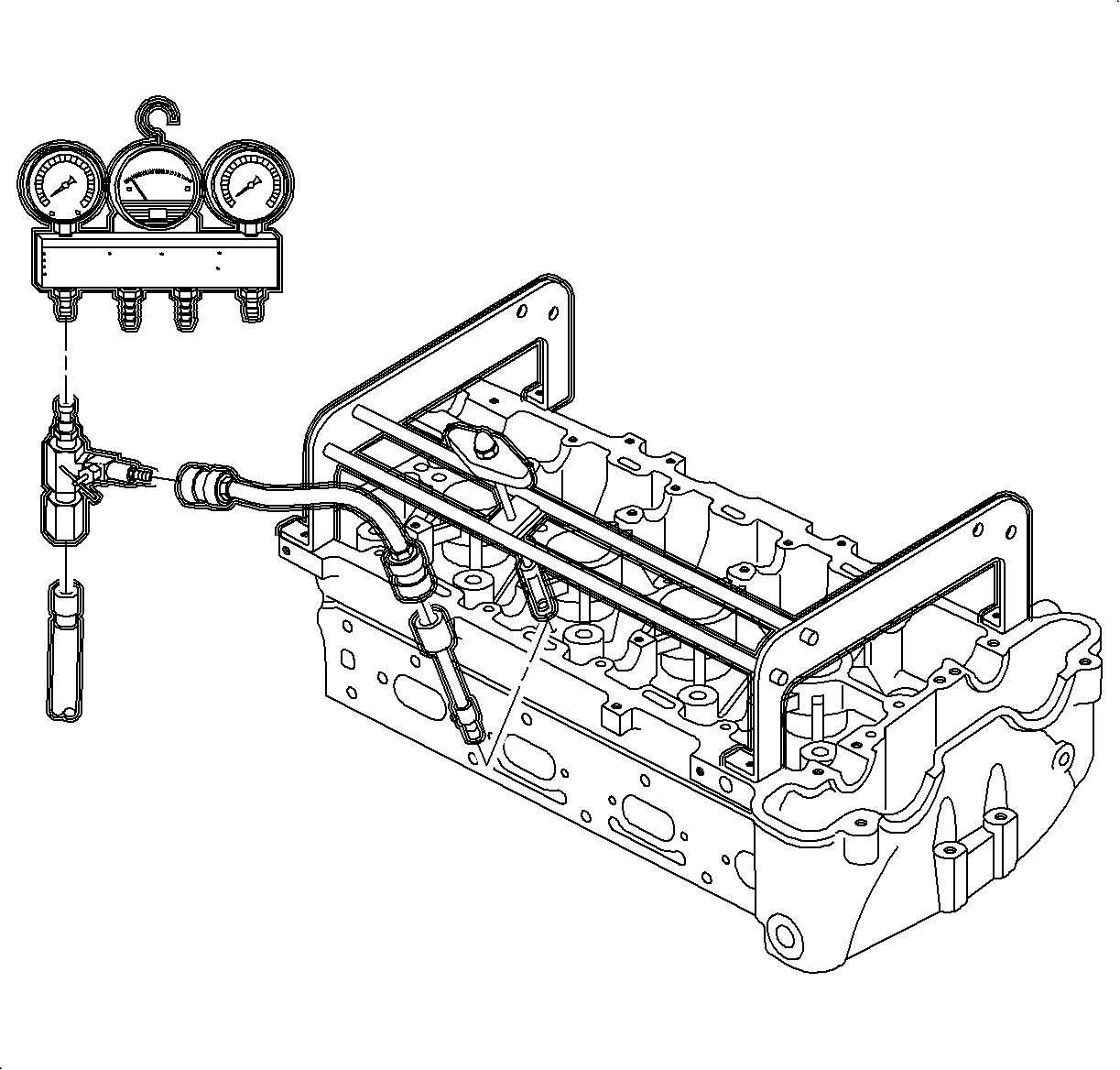
Notice: Care should be used when servicing the valve spring, the retainer and the valve. If air pressure is lost, the valve(s) will drop into the cylinder.
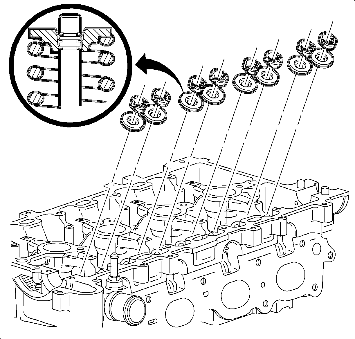
Important: The T-handle compressor was used on the L-Series vehicles but does not provide sufficient clearance when servicing the SUV. Changing the tool from the T-handle compressor rod to the shorter hex rod will allow service for all 4-cylinder applications.

Installation Procedure
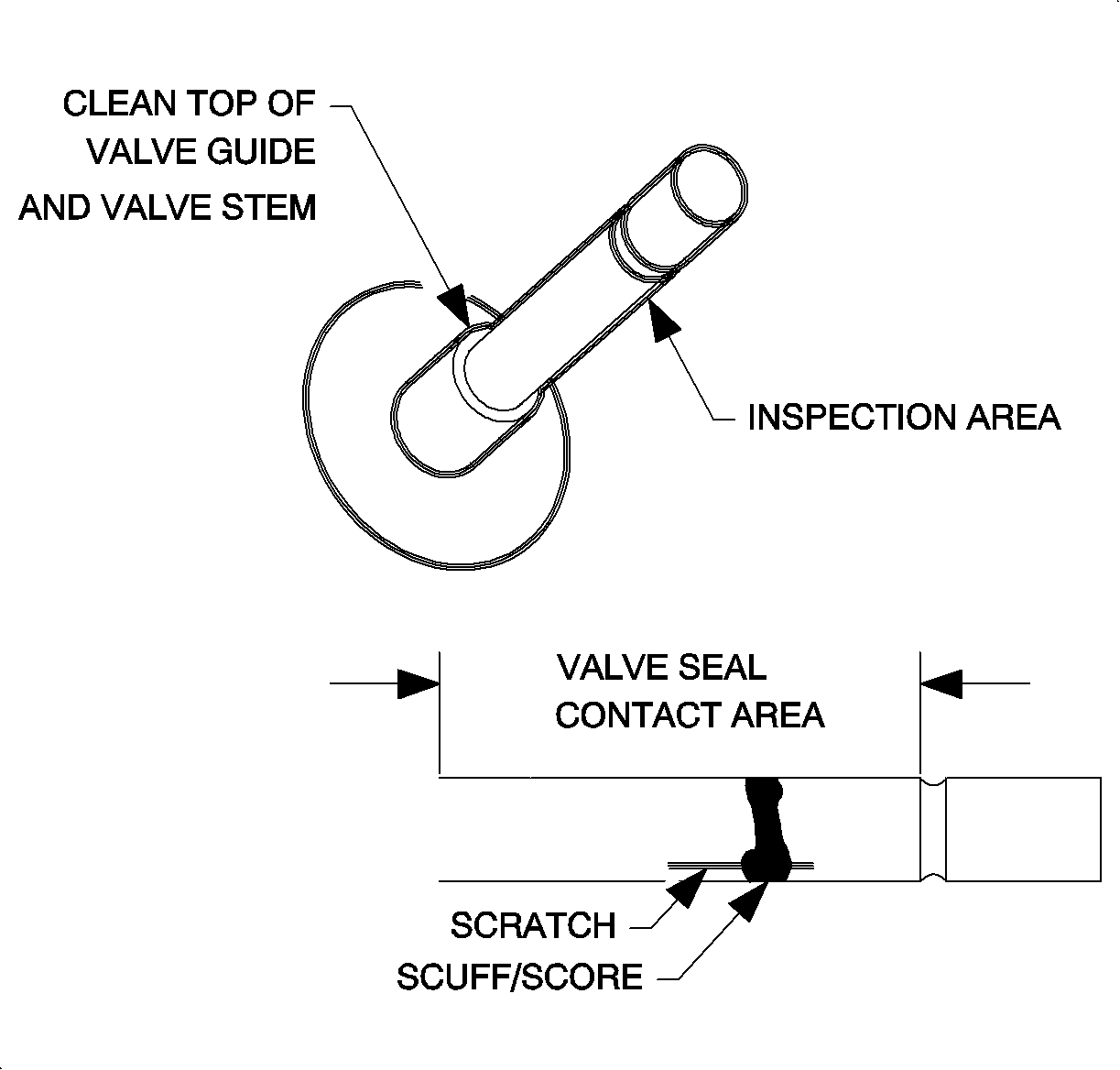
- Inspect the valve stem for scratches, sores and scuffs. Spray the valve stem guide with clean lubricating oil to remove any debris that may be present on the valve stem or the top of the guide.
- Oil the valve stem guide and the valve stem. Install the valve stem oil seal with service tool SA9102E-A .
- Install the valve spring caps.
- Install the valve springs.
- Install the valve retainers and remove the Gage Bar Set SA9127E .
- Install the Gage Bar set SA9127E and pressurize additional cylinders that require service.
- Complete steps 1-6 as necessary.
- Remove the Gage Bar Set SA9127E .
- Remove the Valve Spring Compressor J 43649 .
- Install the lubricated lash adjusters in there correct locations.
- Install the rocker arms (followers).
- Lubricate the camshaft bearing journals with the clean engine oil and install both camshafts.
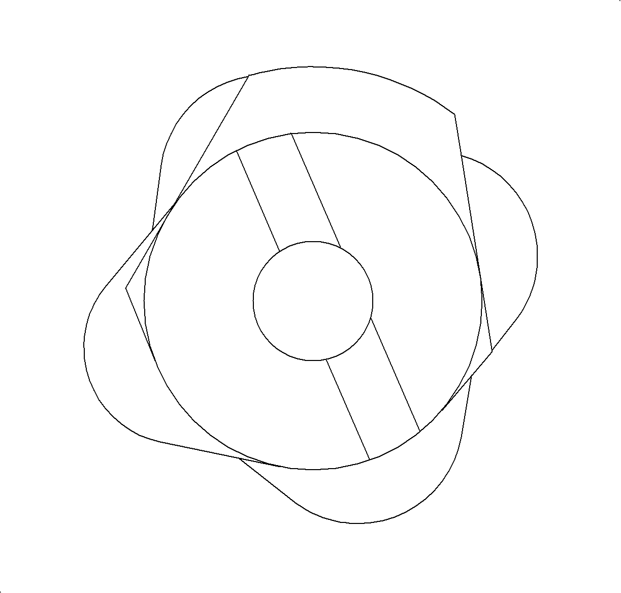
- When installing the camshafts, attempt to position camshaft slot in line with notch on the sprockets.
- Install all bearing caps except for the front cap and the rear intake camshaft cap (if serviced) Tighten down the bearing cap uniformly.
- Slide the camshaft sprocket(s) on the guide pins toward the camshaft(s). Rotate camshaft(s) with a 24 mm open-end wrench to properly align the camshaft(s) and the sprocket(s)
- Install the new camshaft sprocket bolts and tighten. This will pull the camshaft sprockets and the camshafts together. Hold the camshafts with a 24 mm open-end wrench during tightening.
- Remove the Camshaft Sprocket Holding Tool J 43655 .
- Install the front camshaft caps.
- Install the upper timing chain guide and bolts.
- Install the rear intake camshaft bearing cap.
- Install the power steering block off plate.
- Visually inspect the camshaft cover gasket for signs of leakage. The camshaft cover gasket is reusable if not damaged.
- Assemble the camshaft cover and gasket. Use care to make sure that the gasket is located in the retaining groove on the camshaft cover.
- Install the cover on the cylinder head and hand tighten the bolts.
- If removed, install the starter. Refer to Starter Motor Replacement in Engine Electrical.
- If used, remove the J 43653 .
- Re-position the fuel line assembly.
- Install the transfer line fitting to the fuel-to-fuel rail.
- Connect the fuel rail bracket and the bolt to the cylinder head.
- Connect the ground strap to the camshaft cover assembly.
- Connect the degas hose and the clamp to the cylinder head.
- Connect the degas hose clip to the fuel rail.
- Install the spark plugs.
- Install the ignition module assembly to the cam cover and hand tighten the retaining bolts.
- Position the outlet resonator/duct assembly into position.
- Connect the PCV fresh air vent hose assembly.
- Tighten the clamp at the throttle body assembly.
- Position the outlet resonator/duct assembly up with the support bracket and install the push-pin.
- Tighten the clamp at the air cleaner assembly.
- Connect the intake air temperature (IAT) sensor connector.
- Connect the negative battery cable.
Notice: After cylinder block, head, or lifter replacement, it will be necessary to allow the engine to idle for 3-5 minutes. If the lifters are noisy, warm the engine up at less than 200 RPM. After the coolant temperature has reached approximately 85°C (185°F), cycle the engine RPM from idle to 300 RPM for approximately 10 minutes or drive the vehicle 8 kilometers (5 miles) to purge the air. If the air cannot be purged, the faulty lifters will have to be replaced.
Notice: If a valve seal is removed after it has been installed, it must be discarded. The valve stem lock groove will cut the seal's lip during removal. Use extreme care when installing valve retainers and do not damage the valve stems.
Important: Before each valve stem seal is installed, oil the valve stem seal and guide. If a valve stem seal is removed, it must be discarded.



Notice: Refer to Fastener Notice in the Preface section.
Tighten
Tighten the camshaft bearing bolts: 10 N m (89 lb in)
Notice: Verify the timing chain is properly positioned on the fixed guide or guide damage will occur.
Important: Ensure that the alignment slots are correctly aligned with the notches in the camshaft sprockets before final torque is applied.
Important: Verify camshafts are properly timed as outlined in this section prior to starting the engine.
Tighten
Tighten the camshaft sprocket bolts: 85 N m (63 lb ft)+30 degrees.

Tighten
Tighten the camshaft bearing cap bolts: 10 N m (89 lb in).
Tighten
Tighten the timing chain guide bolts: 10 N m (89 lb in).
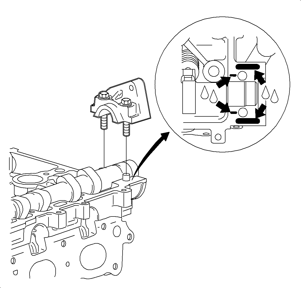
Important: Apply Permatex Flange Sealant to the cylinder head near the rear intake cap as shown.
Tighten
Tighten the intake camshaft rear cap: 25 N m (18 lb ft).
Tighten
Tighten the power steering block off plate: 25 N m (18 lb ft).

Tighten
Tighten the camshaft cover bolts: 10 N m (89 lb in).

Notice: An open-end wrench must be used to support the fuel line to rail connection during loosening/tightening to avoid damaging the fuel rail assembly.
Tighten
Tighten the transfer line fitting-to-fuel rail: 10 N m (89 lb in)

Tighten
Tighten the fuel line bracket bolt: 10 N m (89 lb in)

Tighten
Tighten the camshaft cover ground strap bolts: 10 N m (89 lb in).
Tighten
Tighten the spark plugs: 20 N m (15 lb ft)
Tighten
Tighten the ignition module-to-camshaft cover bolts: 8 N m (71 lb in)

Tighten
Tighten the battery terminal bolt: 17 N m (13 lb ft).
