Removal Procedure
- Record all preset radio stations.
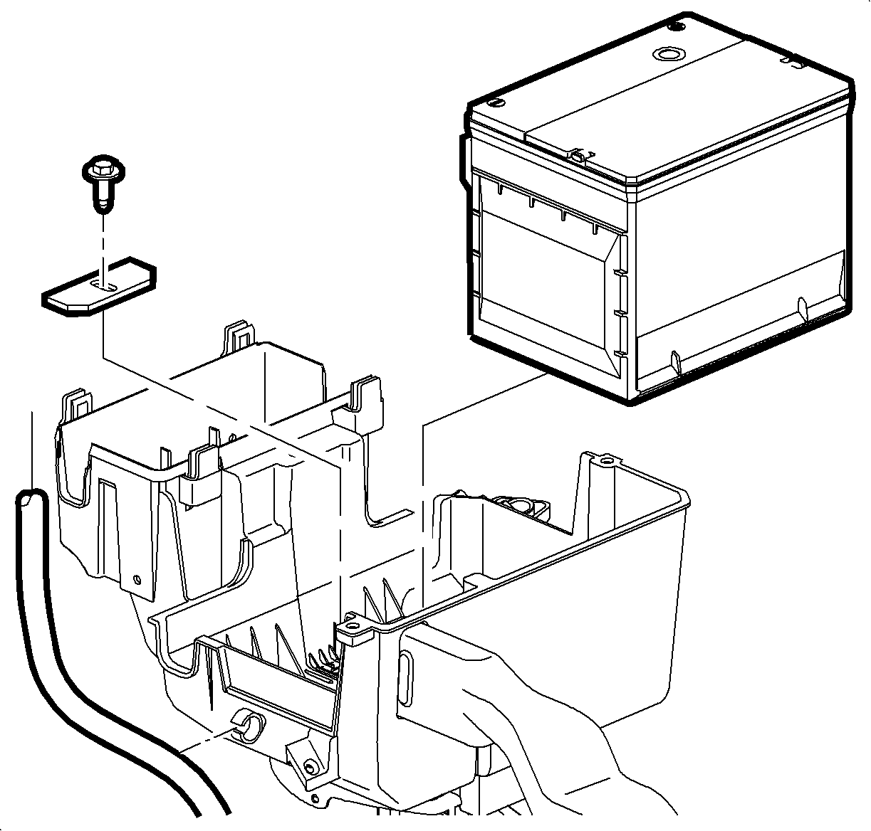
- Remove the battery.
- Remove the battery cooling box. Refer to Battery Cooling Box removal procedure in the General Information section in this service manual.
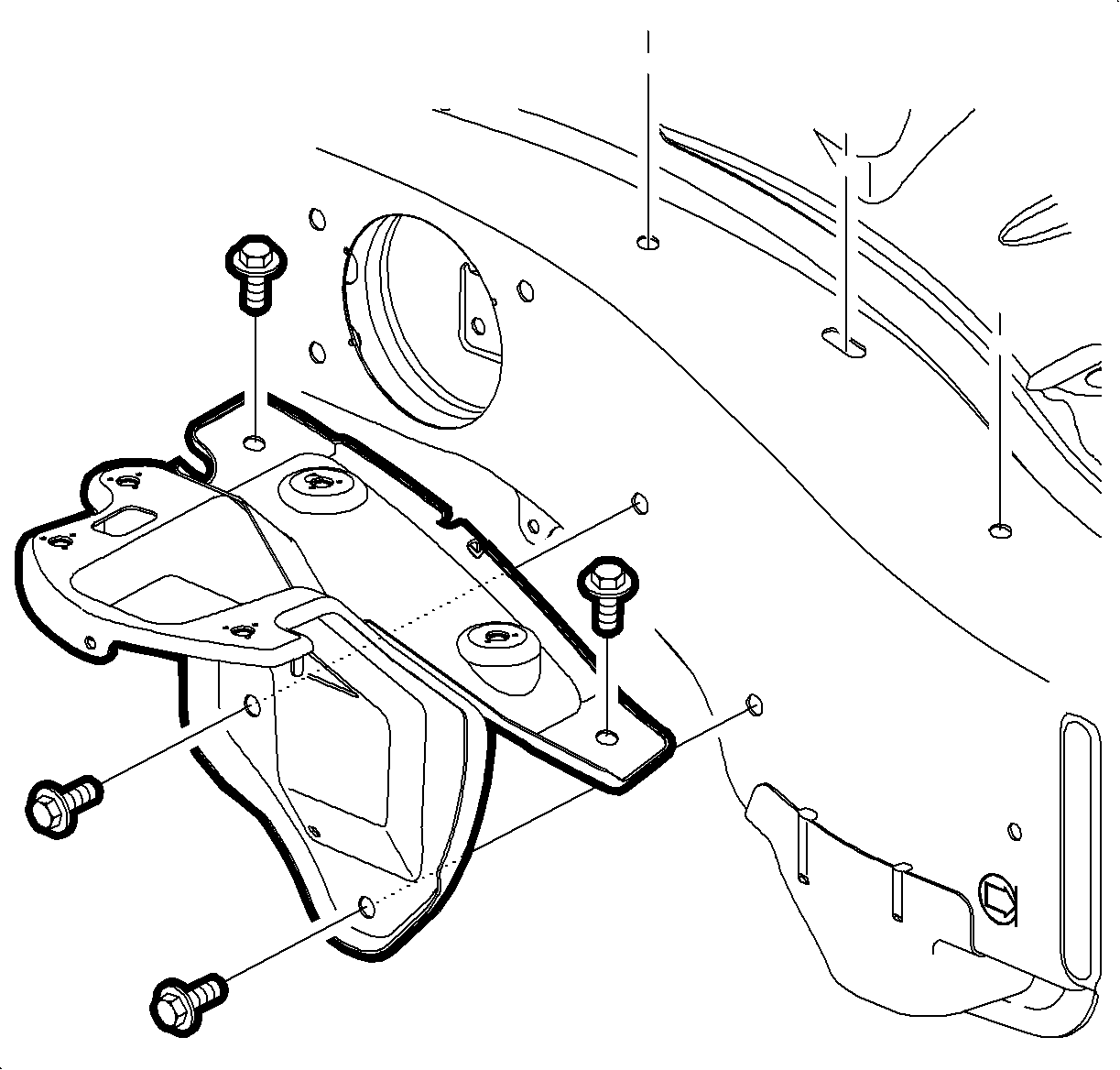
- Remove the battery tray bracket.
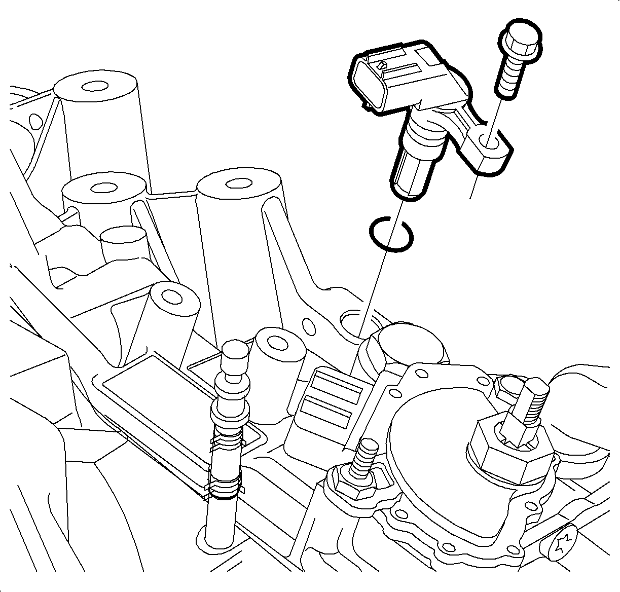
- Disconnect the wiring harness from the input speed sensor.
- Remove the input speed sensor bolt.
- Remove the input speed sensor.
- Remove the input speed sensor O-ring.

Caution: Do not tip the battery over a 45 degree angle or acid could spill causing serious personal injury.
| 2.1. | Remove the battery cover. |
| 2.2. | Disconnect the negative battery cable. |
| 2.3. | Disconnect the positive battery cable. |
| 2.4. | Loosen the battery hold-down screw and remove the battery. |


Important: Do not damage the input speed sensor or the transaxle case.
Installation Procedure
- Apply automatic transaxle fluid to the new input speed sensor O-ring.
- Install the new input speed sensor O-ring onto the input speed sensor.
- Install the input speed sensor onto the transaxle case assembly.
- Install the input speed sensor bolt.
- Connect the wiring harness to the input speed sensor.
- Install the battery tray bracket.
- Install the battery cooling box. Refer to the Battery Cooling Box installation procedure located in this service manual.
Notice: Use the correct fastener in the correct location. Replacement fasteners must be the correct part number for that application. Fasteners requiring replacement or fasteners requiring the use of thread locking compound or sealant are identified in the service procedure. Do not use paints, lubricants, or corrosion inhibitors on fasteners or fastener joint surfaces unless specified. These coatings affect fastener torque and joint clamping force and may damage the fastener. Use the correct tightening sequence and specifications when installing fasteners in order to avoid damage to parts and systems.
Tighten
Tighten the input speed sensor bolt to 6 N·m (53 lb-in).

Tighten
Tighten the battery tray bracket screws to 16 N·m(12 lb-ft)
