Tools Required
| • | J 36346 Fascia Retainer Remover |
| • | J 45341 Drive Axle Remover |
| • | SA91100C Tie Rod Separator |
| • | SA9173G Slide Hammer |
Removal Procedure
- Record all preset radio stations.
- Remove the battery.
- Remove the battery cooling box. Refer to Battery Cooling Box Battery Box Replacement removal procedure in Engine Electrical.
- Remove the battery tray bracket.
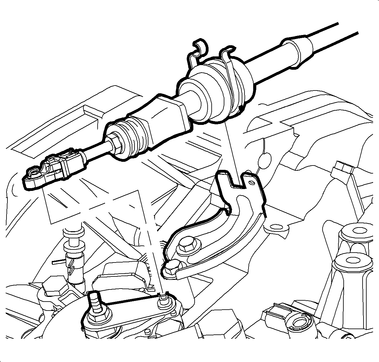
- Use the J 36346 to disconnect the control cable from transaxle range switch assembly lever.
- Disconnect the control cable from the control cable bracket.
- Disconnect the transaxle range switch harness connectors.
- Disconnect the input and output speed sensor harness connectors.
- Disconnect the harness from the transaxle range switch stud and the shifter cable bracket.
- Remove the positive battery cable from the transaxle stud.
- Remove the headlamp fasteners and wire the radiator to the radiator core support to hold the radiator in place as the cradle is removed.
- Install the engine support tool.
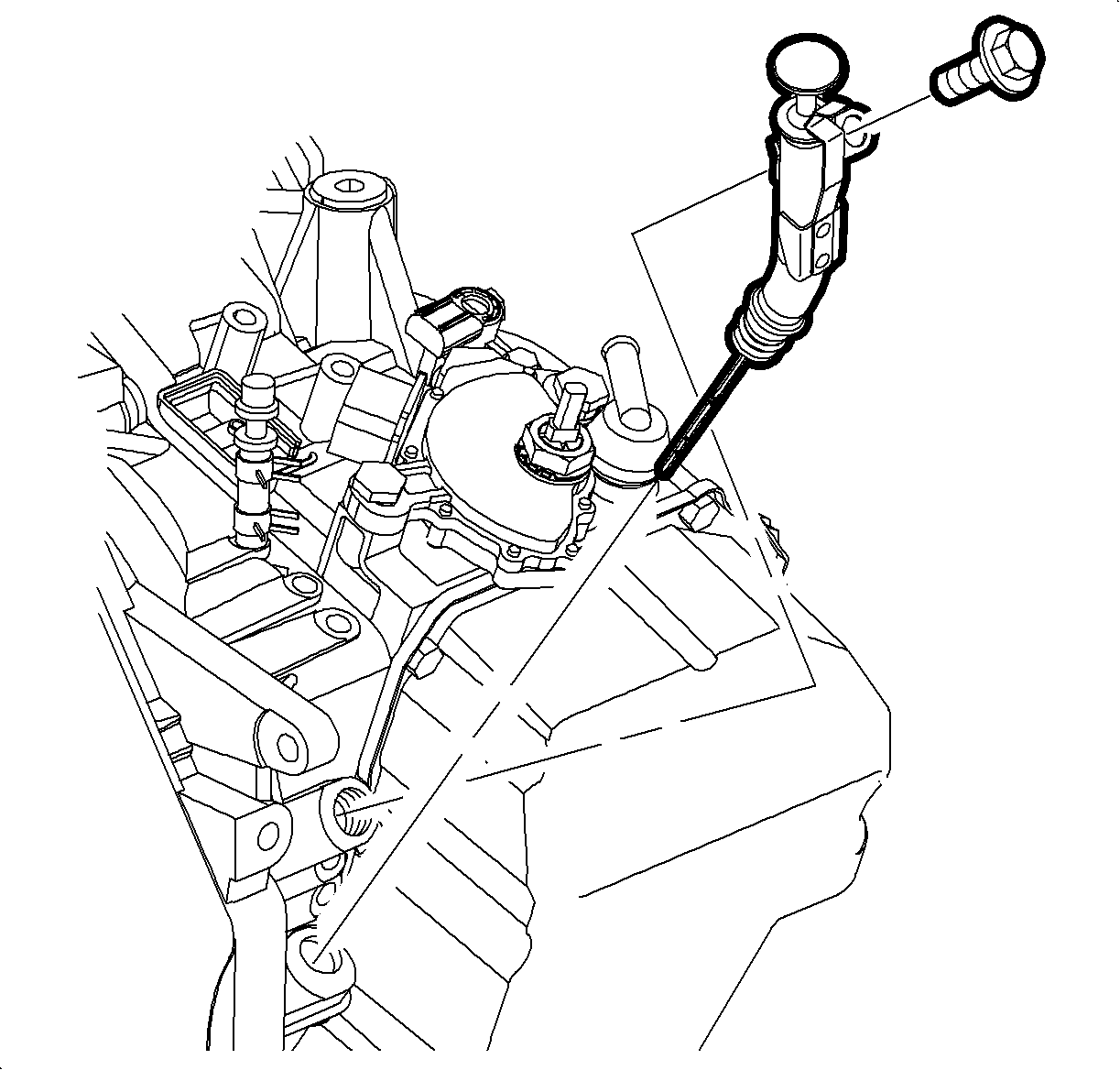
- Remove the transaxle fluid level indicator assembly.
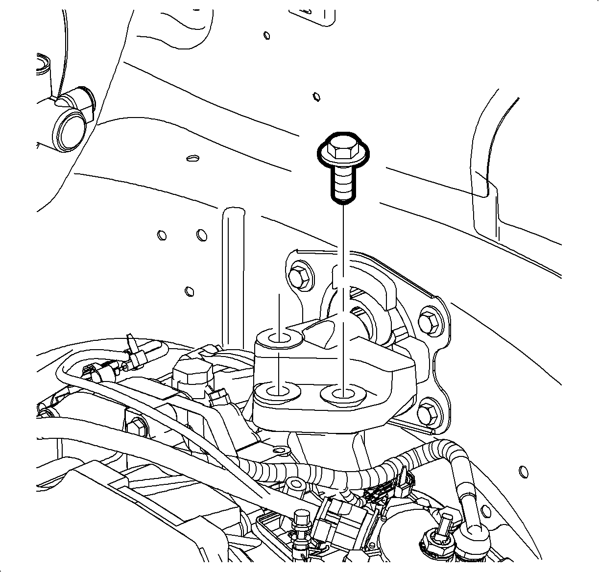
- Remove the upper left-hand transaxle mount bolts and remove the mount.
- Position the vehicle on a hoist and raise the vehicle.
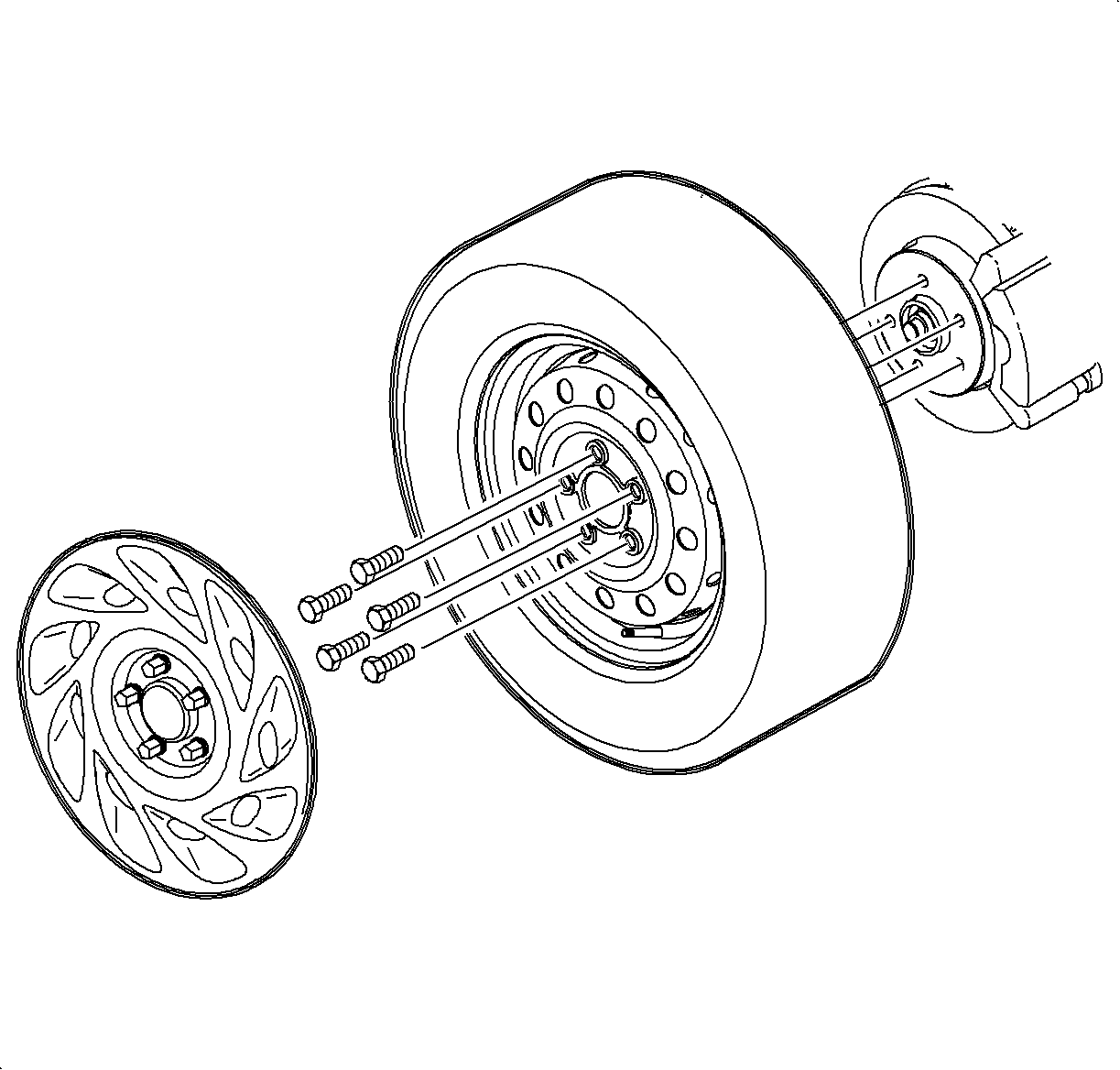
- Remove both front wheel and tire assemblies.
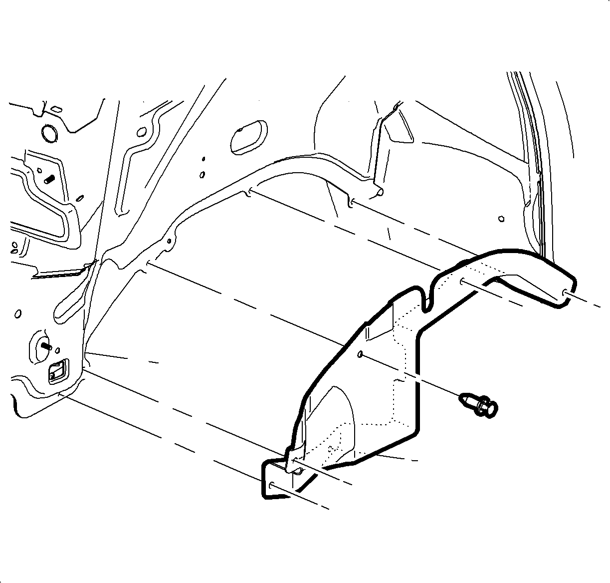
- Remove the left-side and the right-side inner splash shields.
- Remove the front air deflector-to-cradle pushpins to allow the deflector to flex. The front air deflector does not need to be removed.
- Drain the transaxle fluid.
- Remove the transaxle cooler line assembly nut from the transaxle.
- Remove the transaxle cooler lines from the transaxle.
- Disconnect the drive shaft from the power take-off unit - PTU and support the drive shaft. Mark the alignment position of the PTU and the drive shaft.
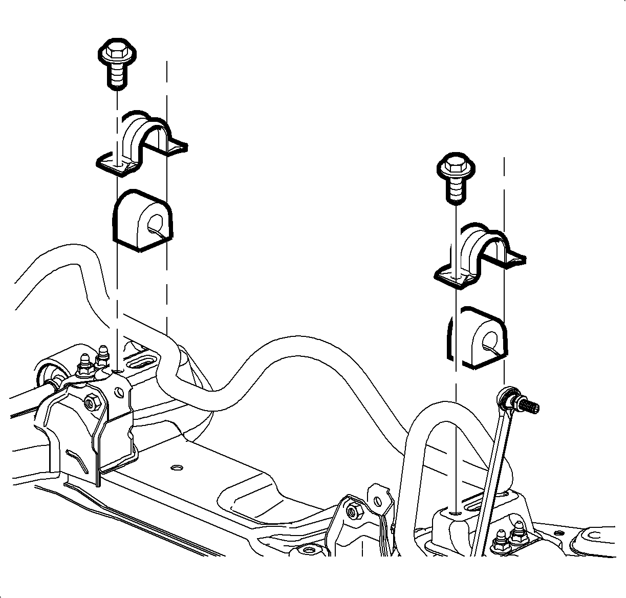
- Disconnect the lower stabilizer nut from the cradle on both sides of the vehicle.
- Remove the rack and pinion bolts from the cradle.
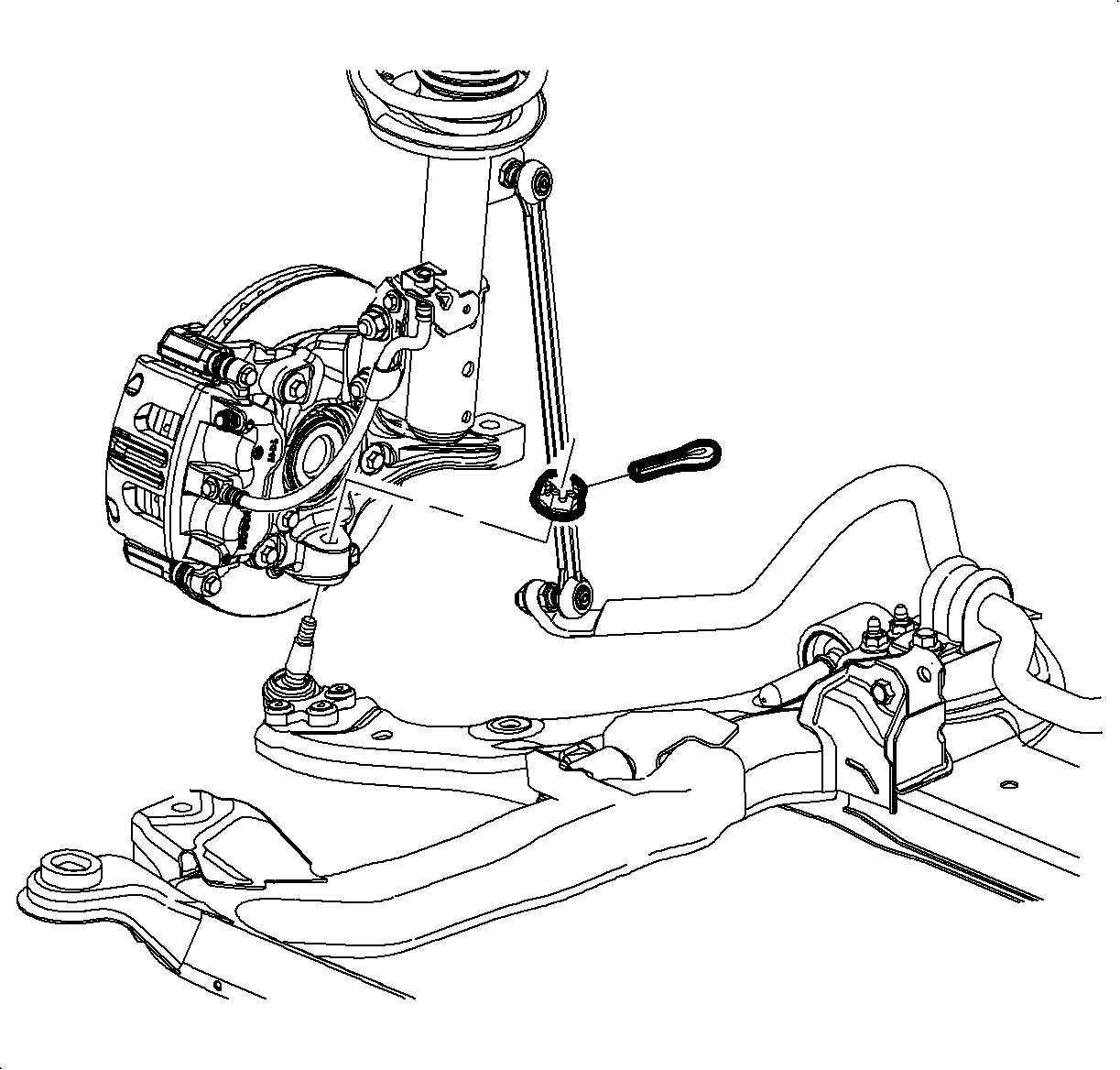
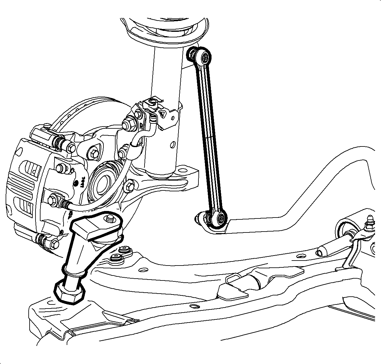
- Remove the lower control arm ball stud cotter pin and nut.
- Discard the cotter pin.
- Separate the ball stud from the knuckle.
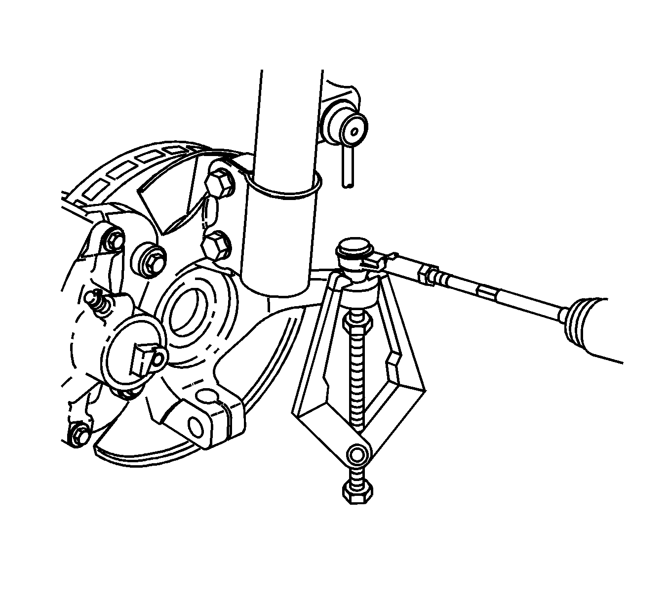
- Use the SA91100C to separate the knuckle from the tie rod on both sides of the vehicle.
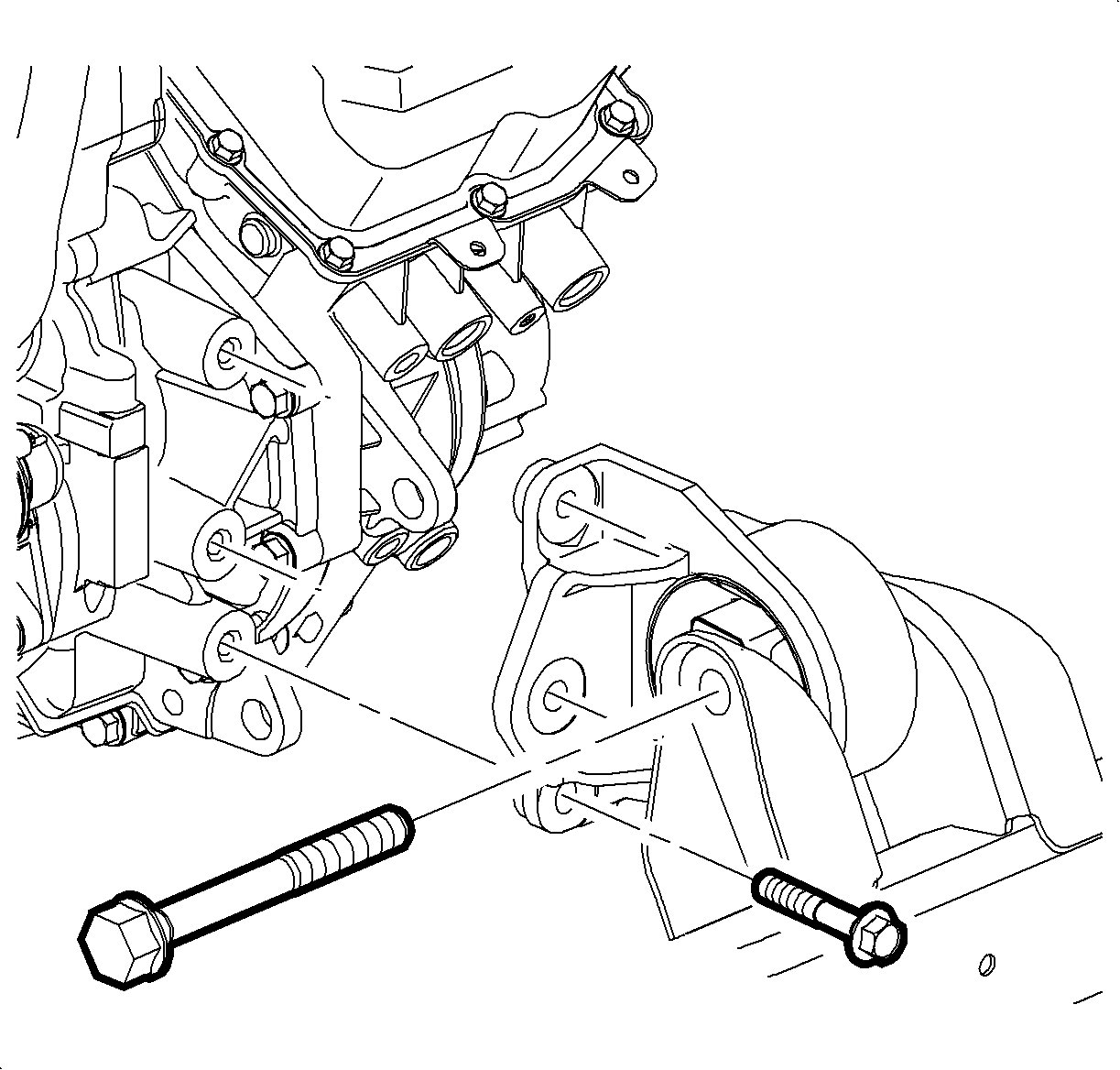
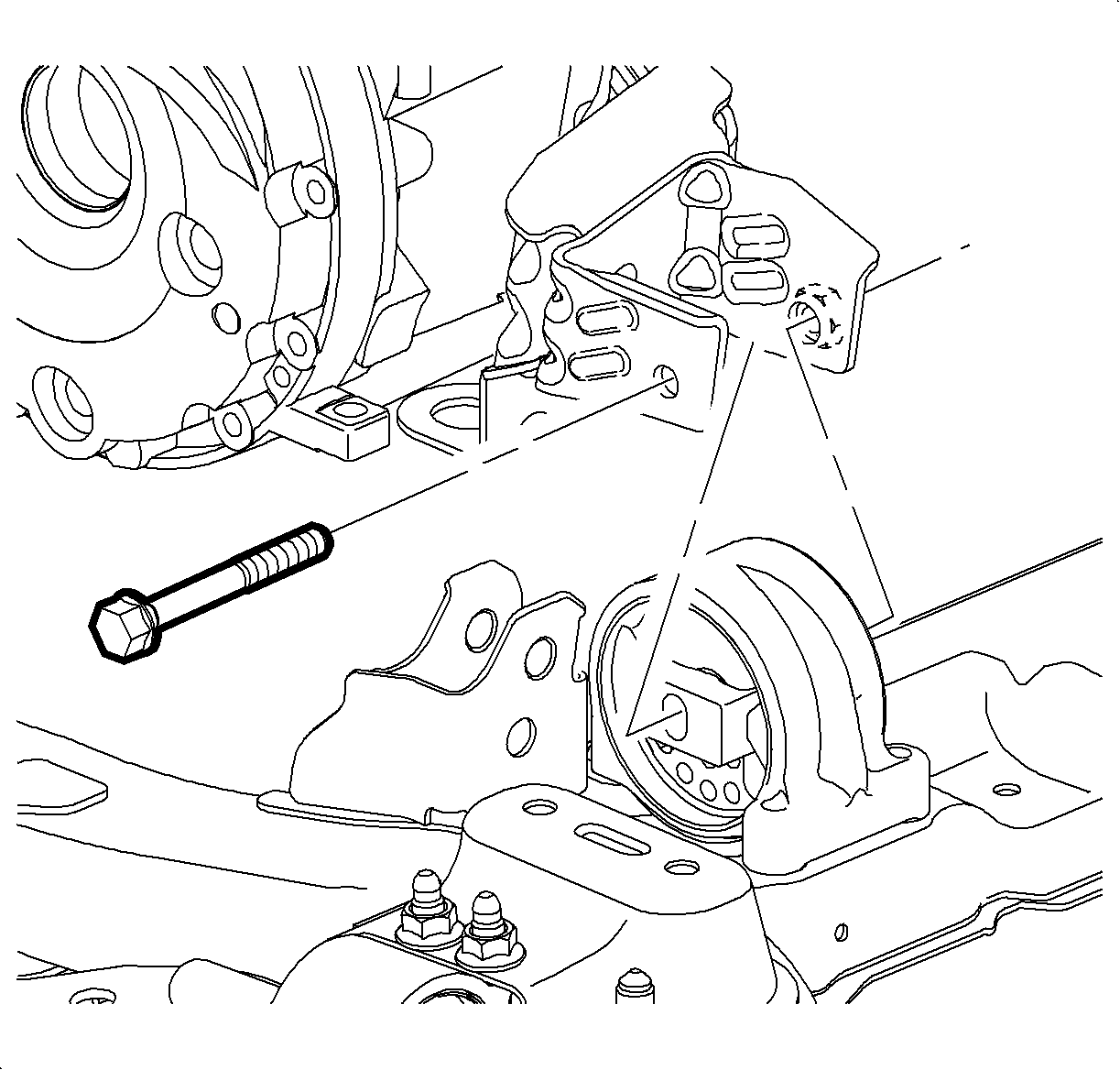
- Remove the front pitch restrictor bolts, through-bolt, and the front pitch restrictor.
- Remove the rear pitch restrictor through-bolt from the cradle.
- Position the support table under the cradle.
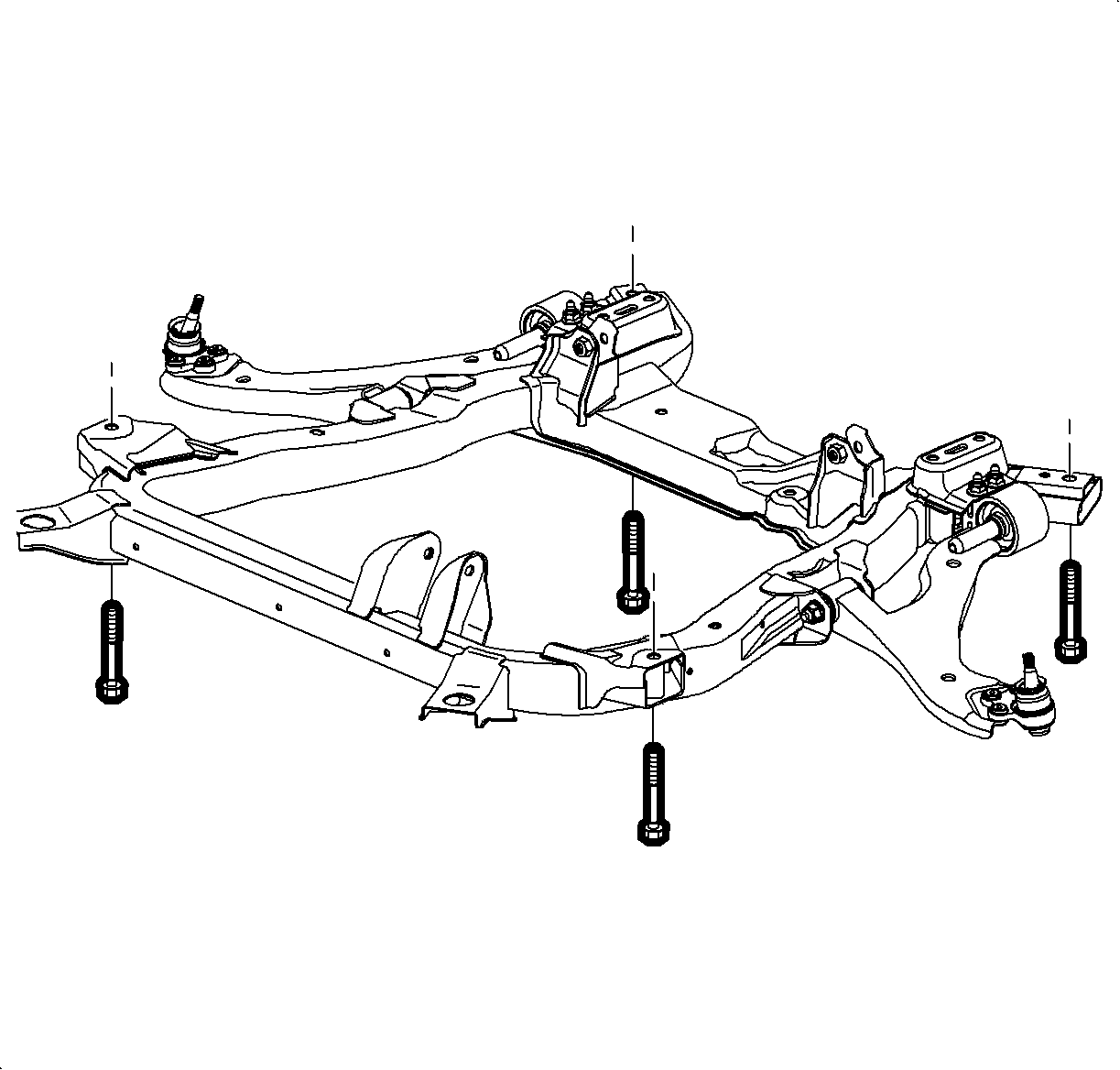
- Remove the cradle bolts and lower the cradle onto the support table.
- Use the J 45341 and the SA9173G to separate the left axle shaft from the transaxle and tie the strap out of the way.
- Use the J 45341 and the SA9173G to separate the right axle shaft from the PTU and tie the strap out of the way.
- Remove the PTU-to-engine bracket bolts and remove bracket.
- Disconnect the starter wiring harness.
- Remove the starter bolts and starter.
- Turn the crankshaft clockwise to gain access to the torque converter-to-flexplate bolts.
- Remove the torque converter-to-flexplate bolts through the starter hole.
- Remove 3 lower transaxle-to-engine bolts.
- Remove 1 engine-to-transaxle bolt located above the PTU.
- Lower the vehicle and secure the transaxle to a transaxle jack or support table for separating the engine and the transaxle.
- Separate the transaxle from the engine carefully.
- Lower the transaxle from the vehicle carefully.
- Remove the PTU vent hose.
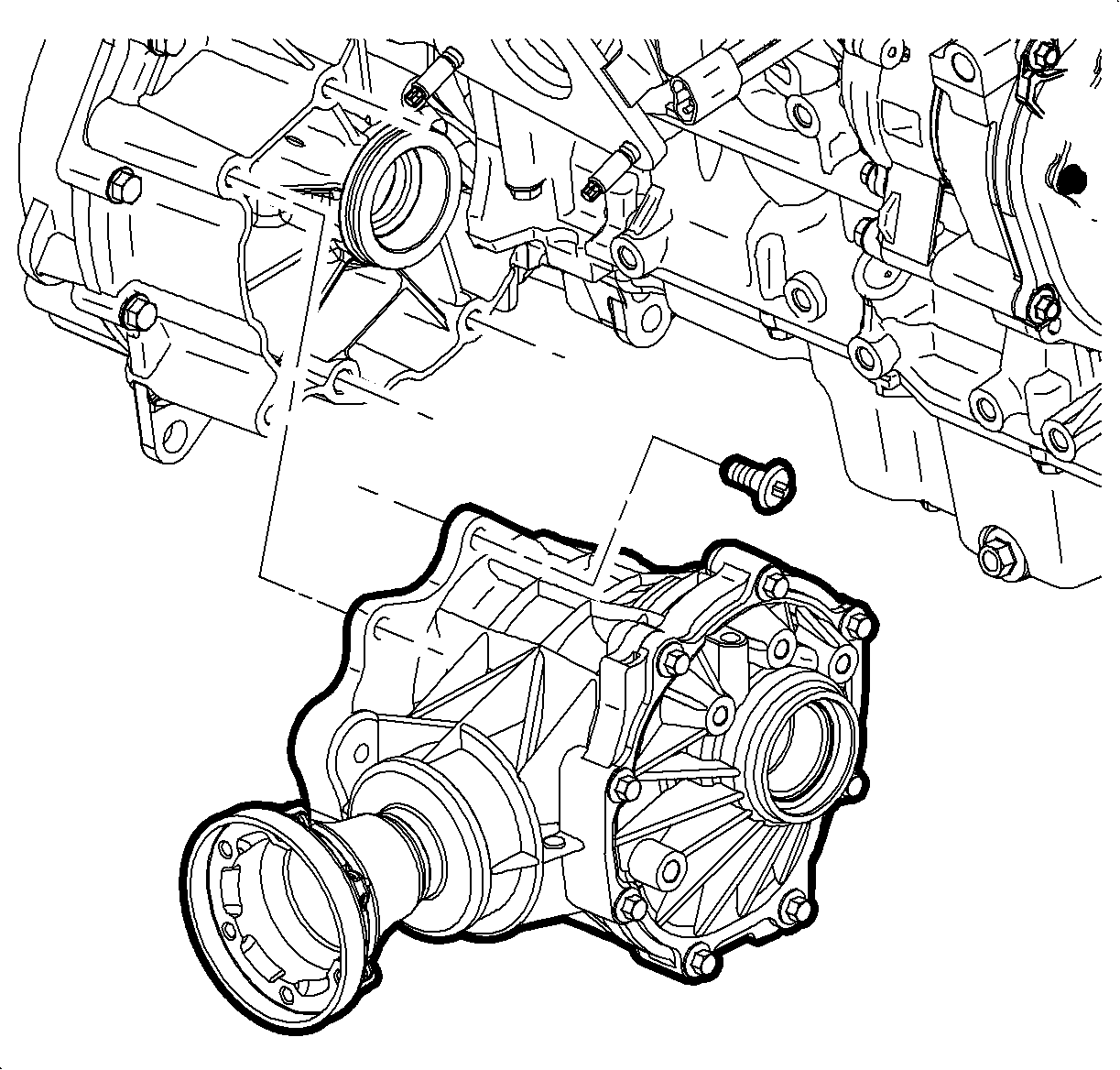
- Remove the PTU bolts and separate the PTU from the transaxle.
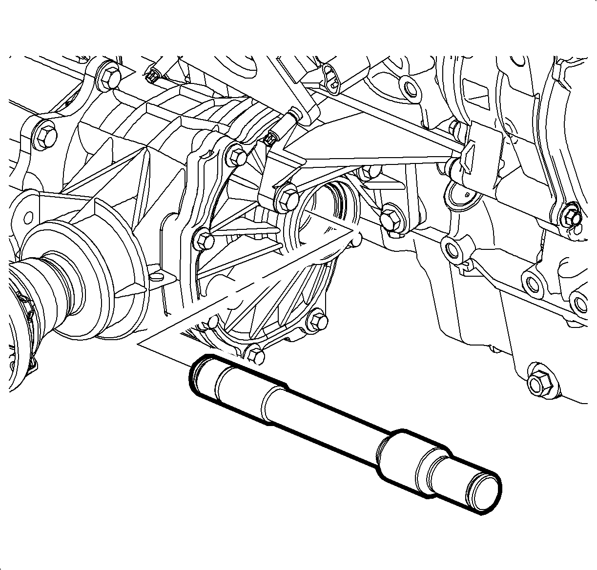
- Remove the stub shaft from the transaxle.
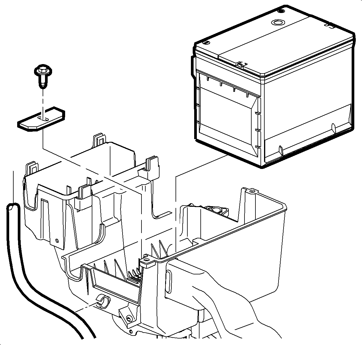
Caution: Do not tip the battery over a 45 degree angle or acid could spill causing serious personal injury.
| 2.1. | Remove the battery cover. |
| 2.2. | Disconnect the negative battery cable. |
| 2.3. | Disconnect the positive battery cable. |
| 2.4. | Loosen the battery hold-down screw and remove the battery. |
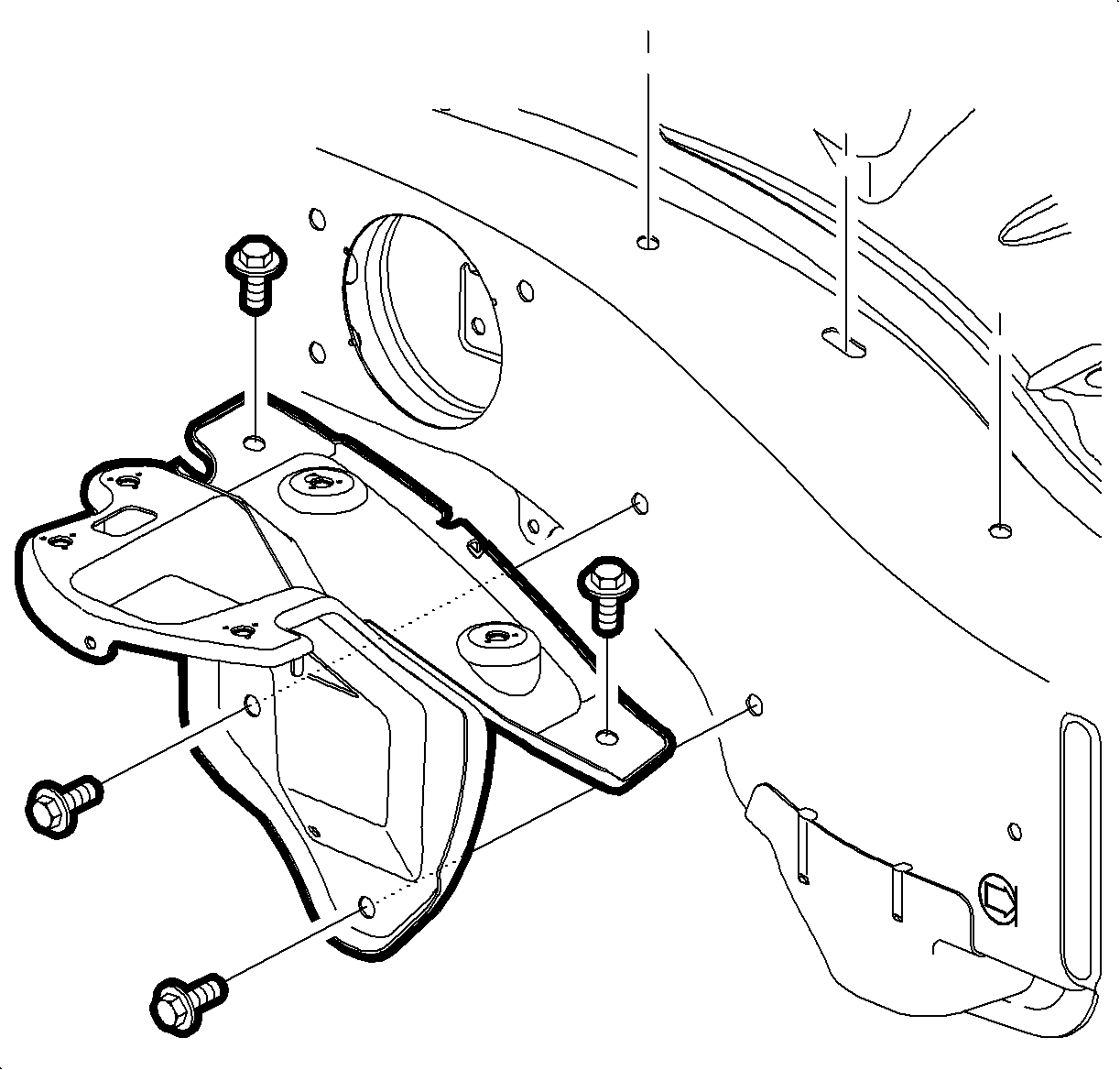
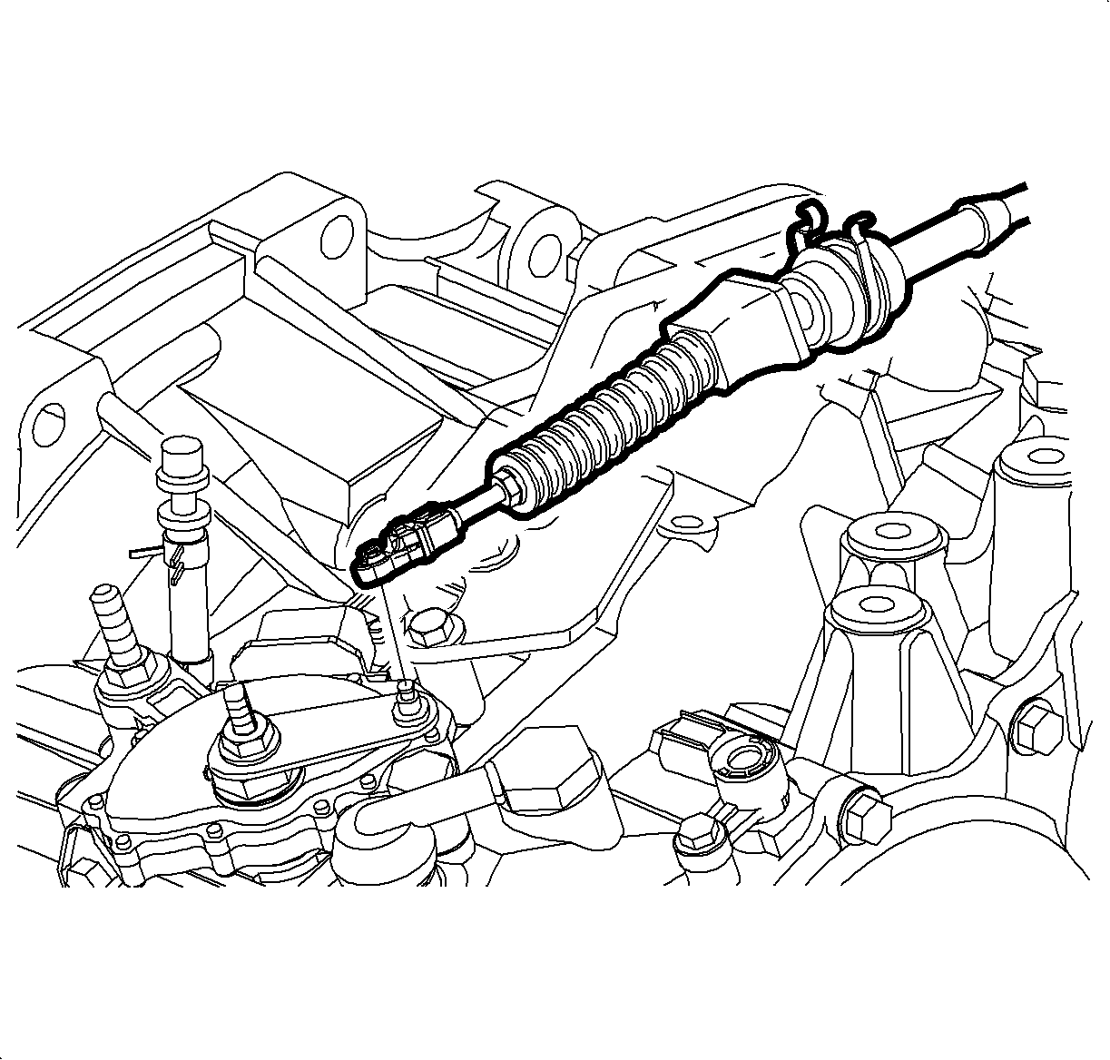
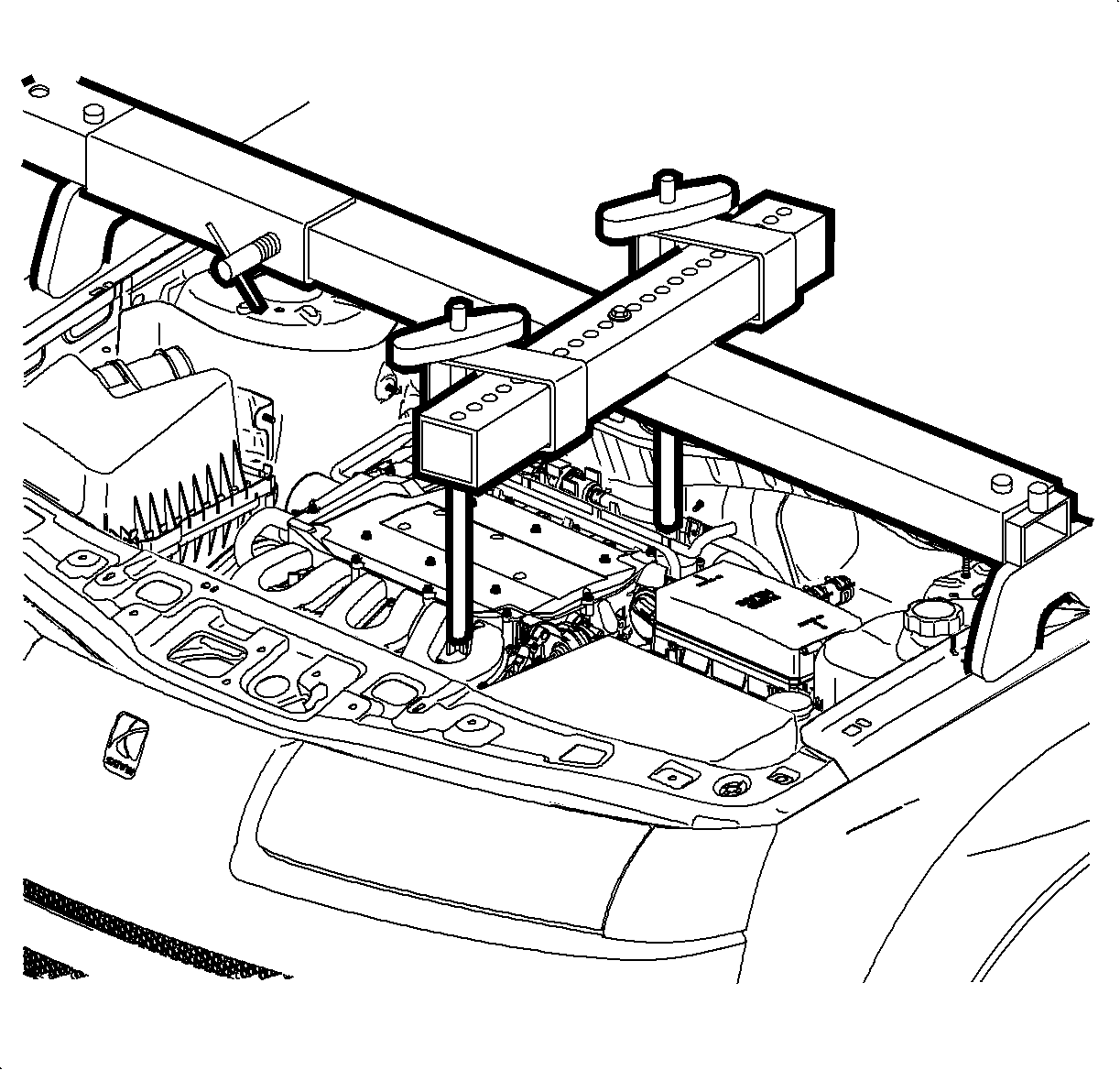
Caution: Ensure that the vehicle is properly supported and squarely positioned. To help avoid personal injury when a vehicle is on a hoist, provide additional support for the vehicle on the opposite end from which the components are being removed.
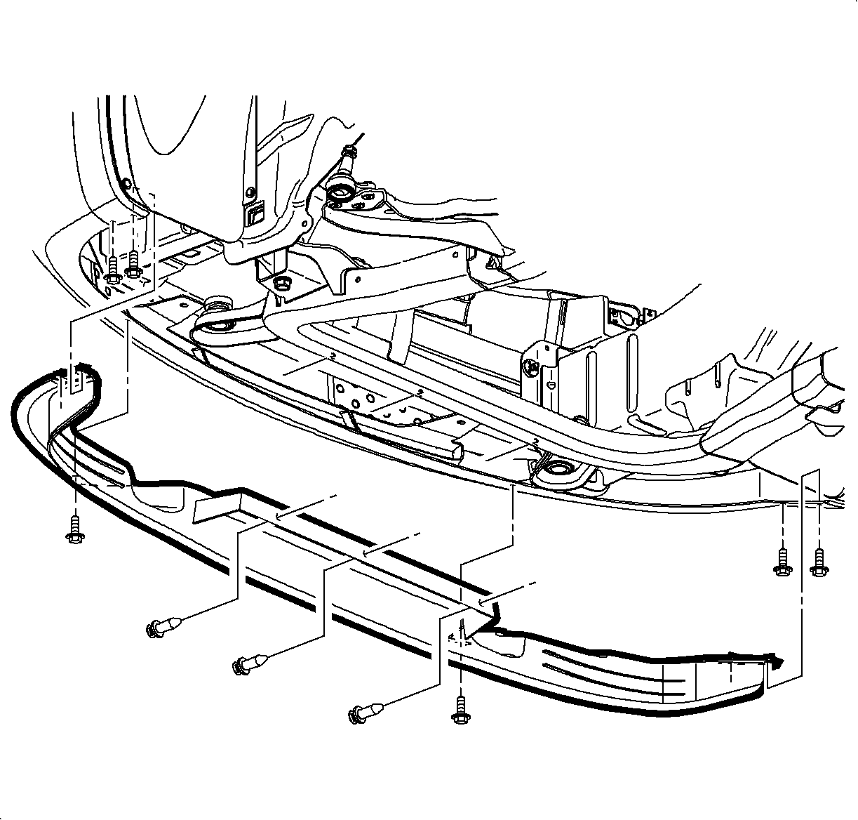
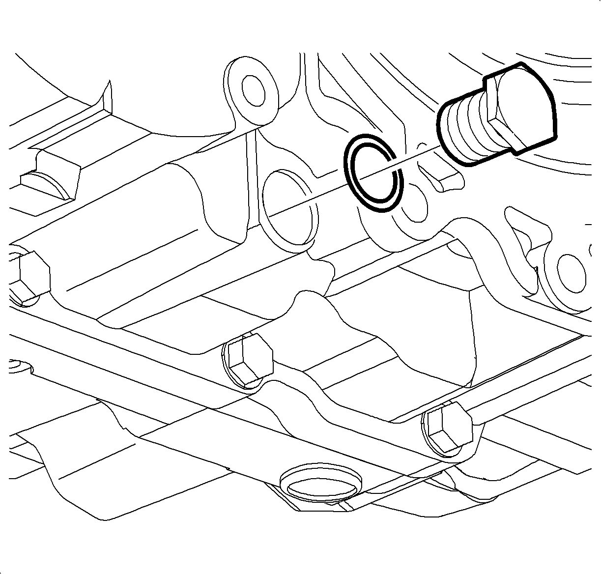
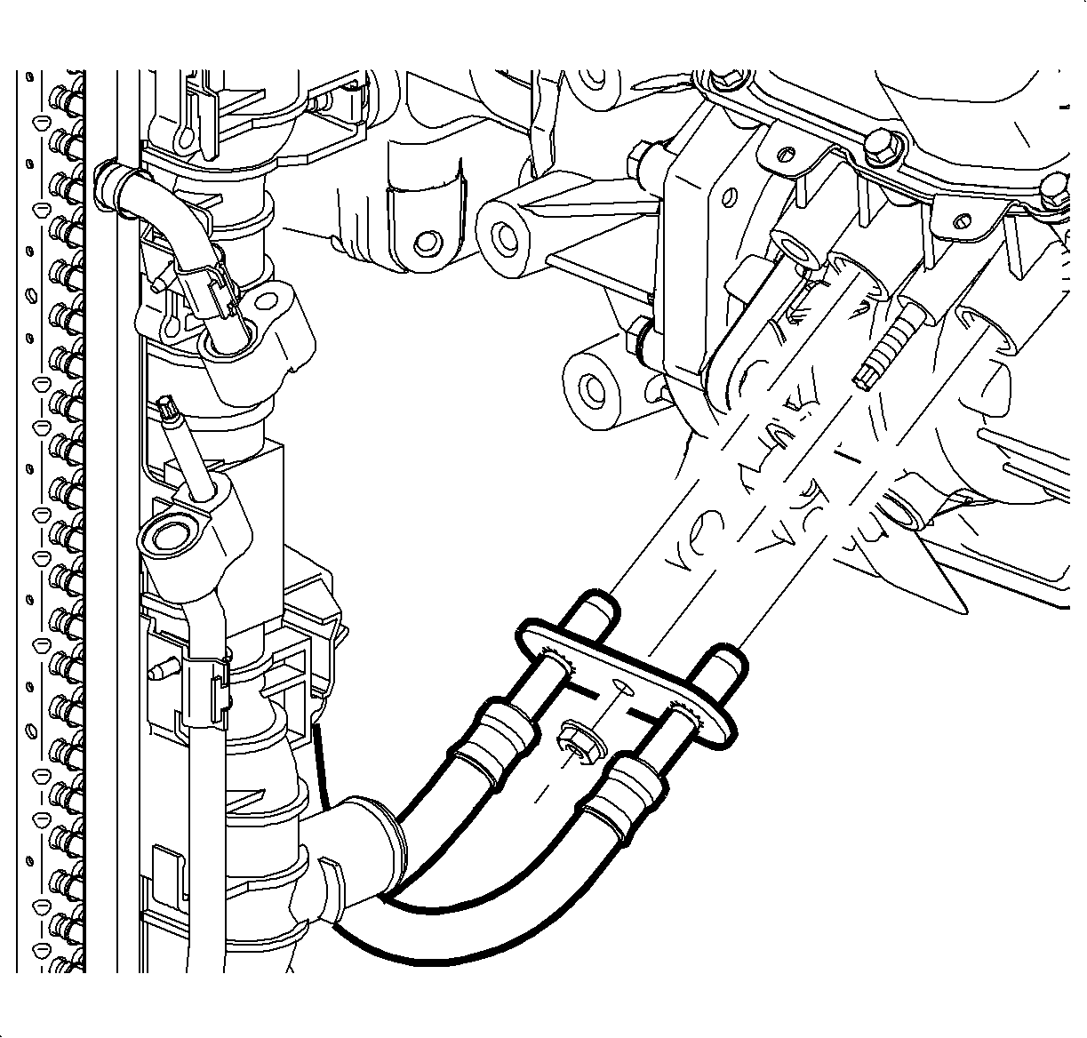
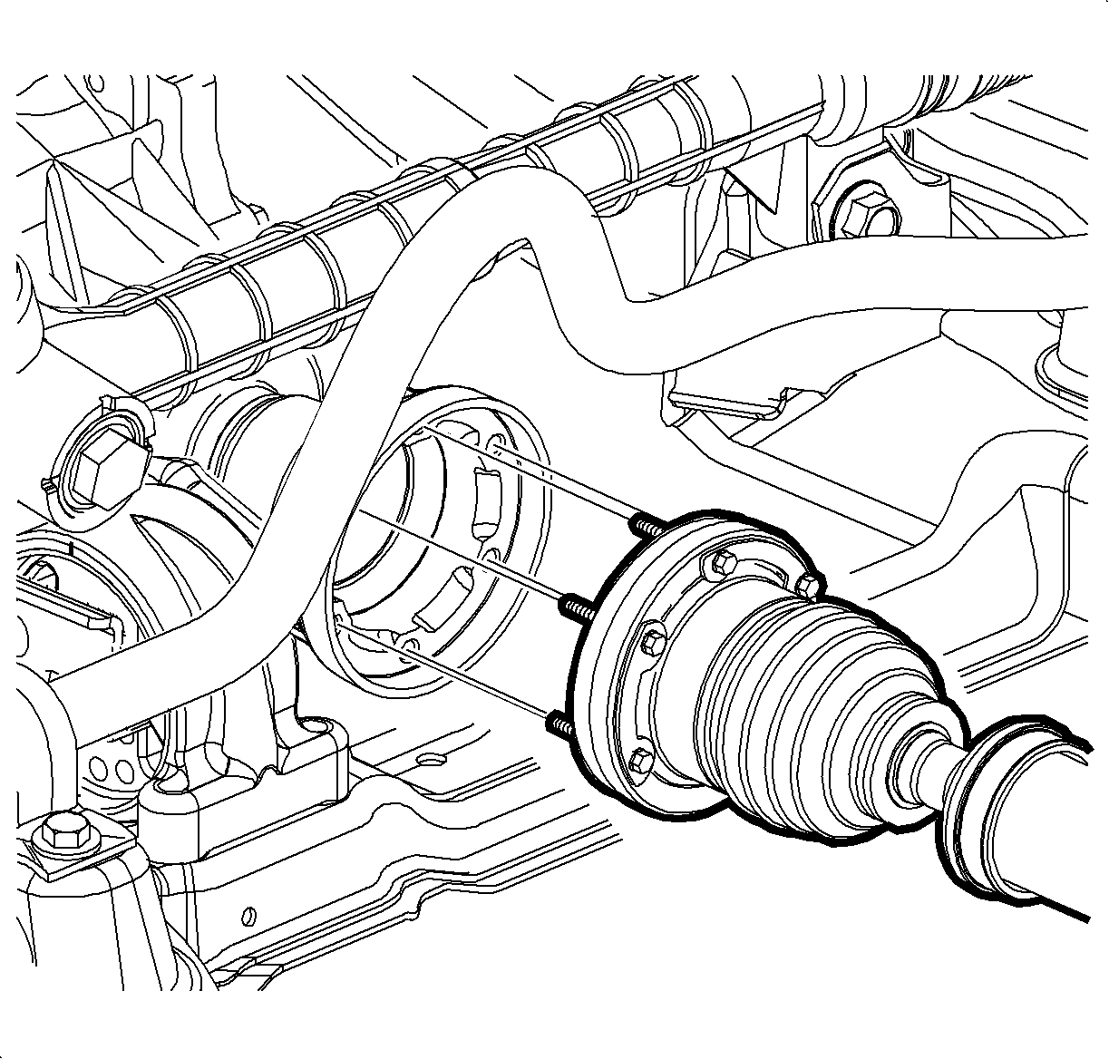
Important: Mark the alignment position of the PTU and the drive shaft.
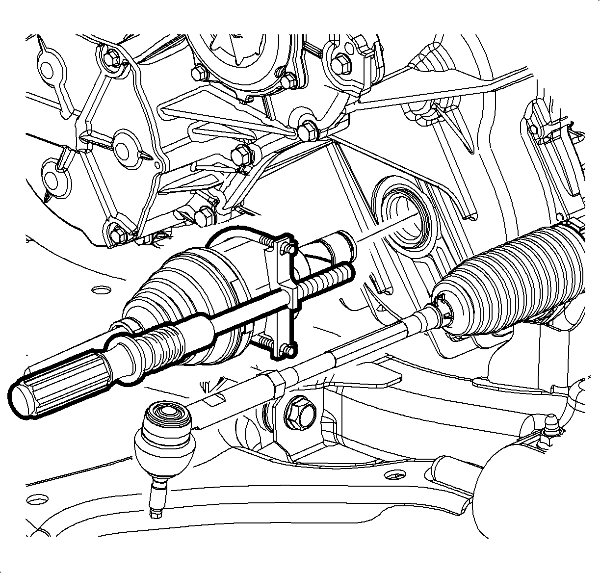
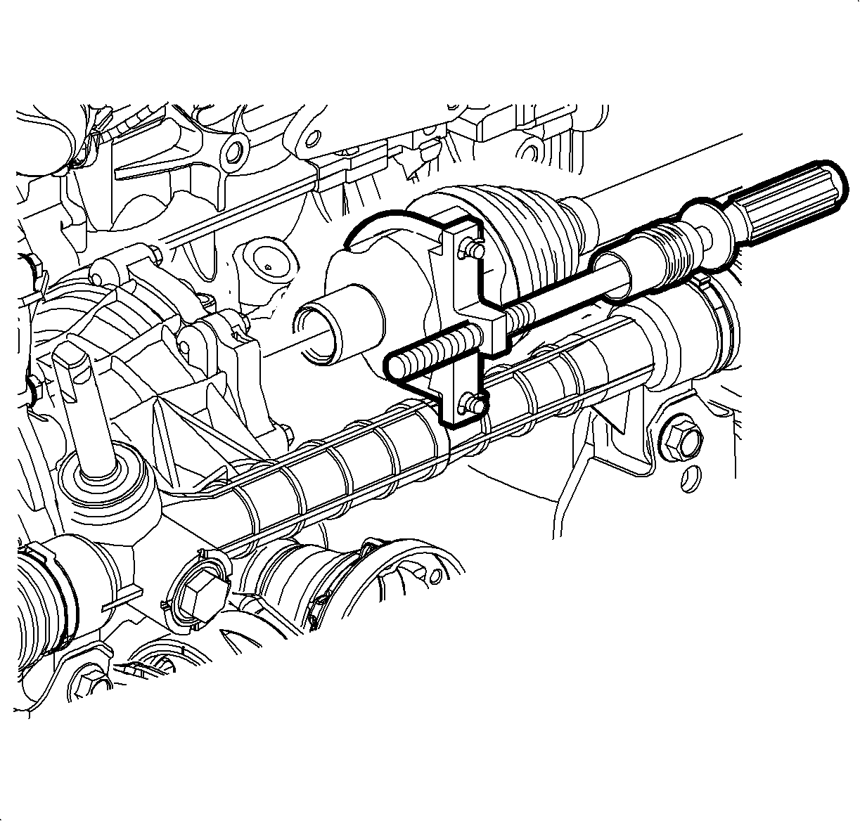
Important: Do not damage the J 45341 .
Important: The stub shaft may disengage from the PTU and separate from the axle. If this occurs, plug the PTU stub shaft hole to prevent fluid loss.
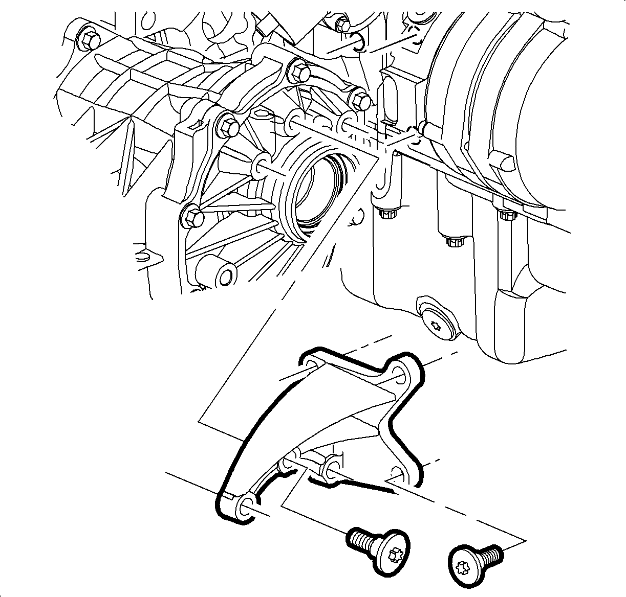
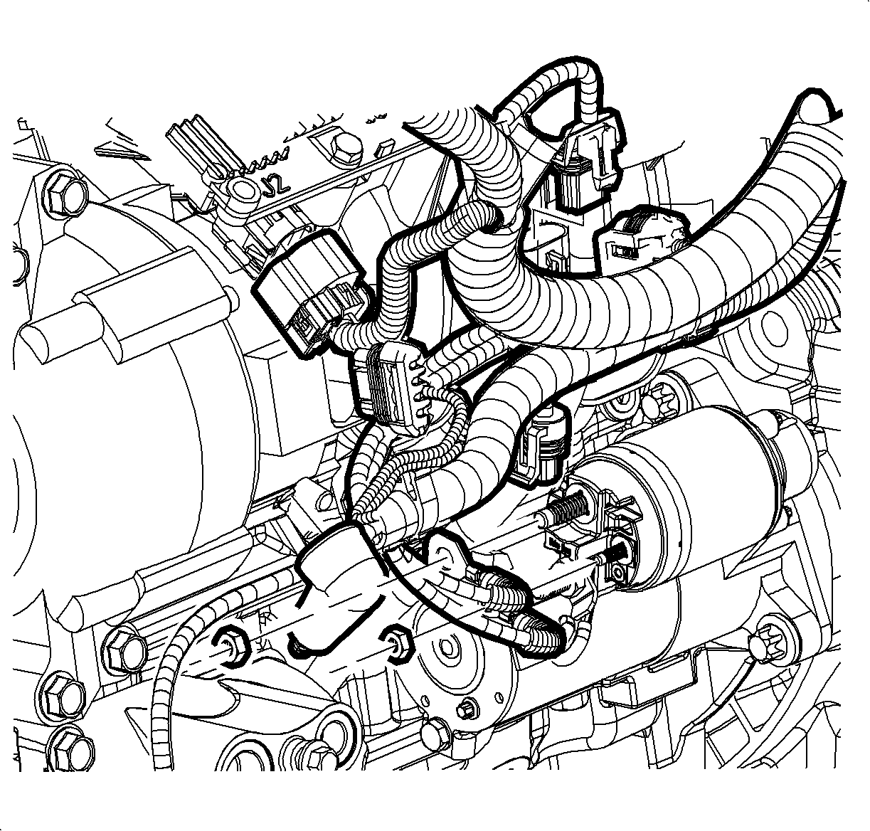
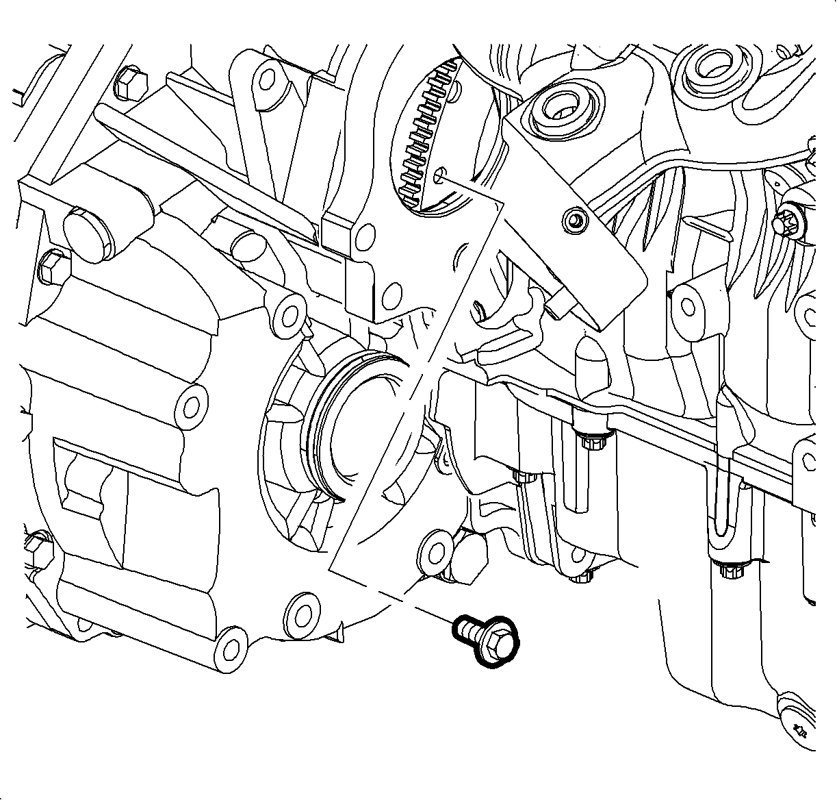
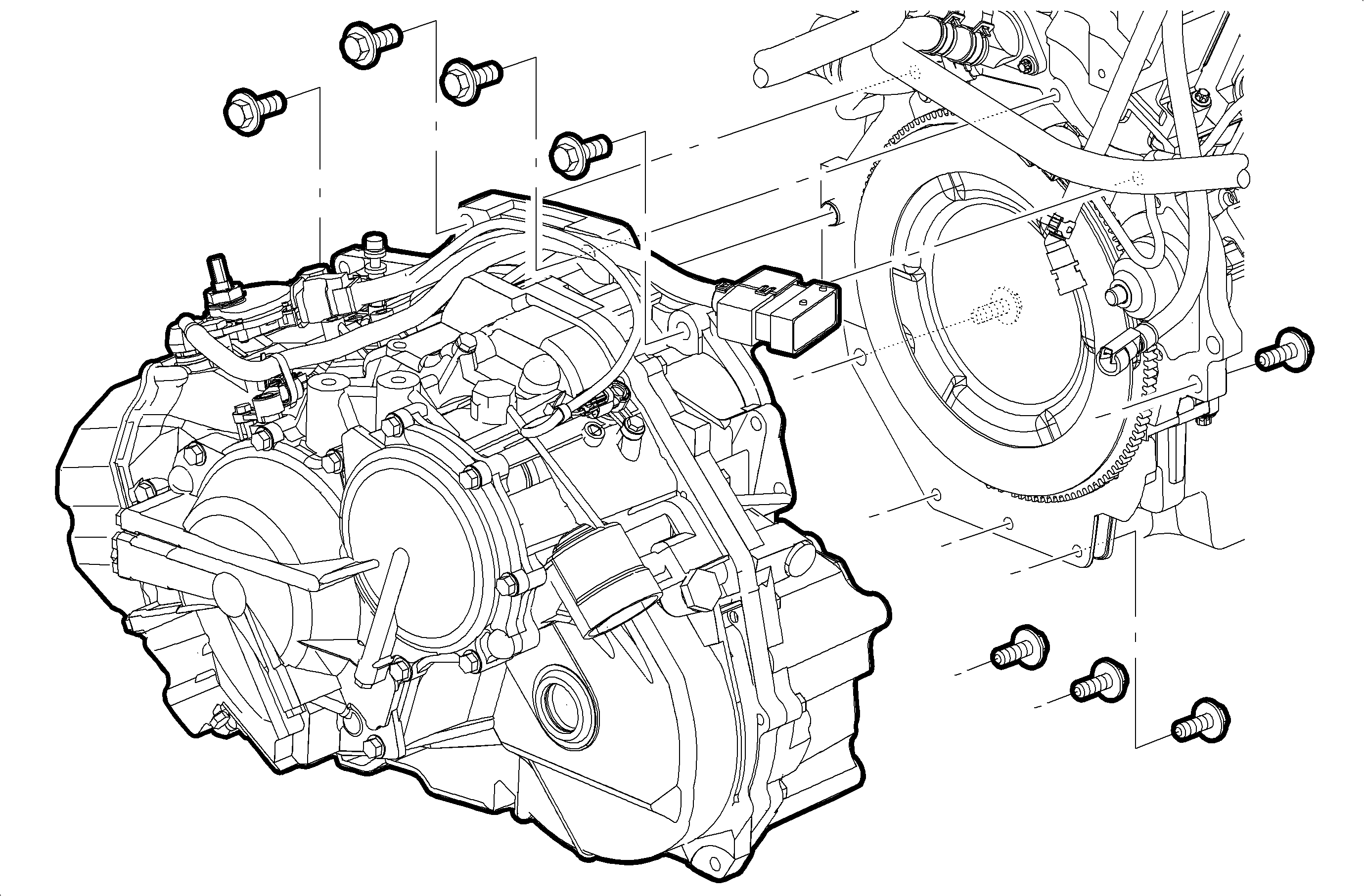
Important: The torque converter has a long pilot shaft. Do not put an excessive load on the shaft. Do not lower the transaxle until the shaft is clear of the engine crankshaft.
Important: Do not damage the mating surfaces of the engine or the transaxle.
Tools Required
| • | J 44015 Tie Rod Installer |
| • | SA91112T Axle Seal Protector |
Installation Procedure
- Position the vehicle on a hoist and raise the vehicle.
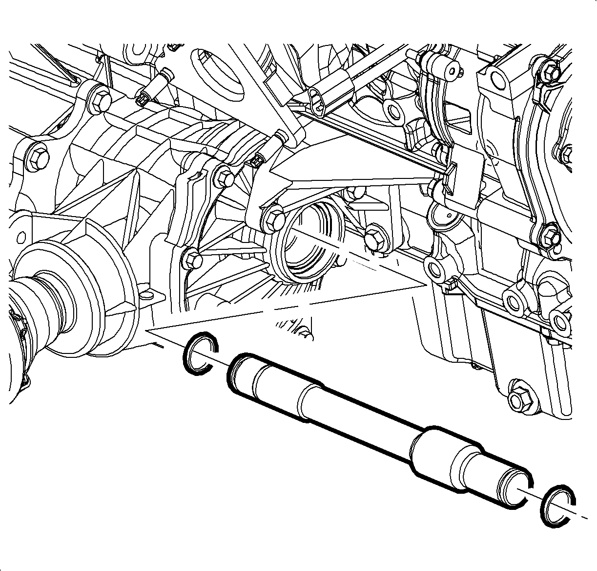
- Install new stub shaft retaining rings.
- Install the power take-off unit (PTU) bolts and the PTU unit to the transaxle.
- Install stub shaft into transaxle.
- Install PTU vent hose.
- With the transaxle supported, carefully raise the transaxle. It may be helpful to lower the vehicle down around the transaxle.
- Carefully assemble the engine to the transaxle.
- Install the upper and lower transaxle-to-engine bolts.
- Install the engine-to-transaxle bolt located above the PTU.
- Install PTU-to-engine bracket assembly.
- Install exhaust downpipe.
- Rotate the crank and align the net hole of the flexplate through the starter opening.
- Install the torque converter-to-flexplate bolts through the starter hole.
- Install the starter and the starter bolts
- Install starter wiring harness.
- Install the right axle shaft to PTU stub shaft.
- Install a new retaining ring on the left axle shaft.
- Install the SA91112T inside the left axle seal
- Lubricate the axle with transaxle fluid.
- Carefully install the left axle shaft into the transaxle.
- Remove the SA91112T after the splines clear the seal protector, but before the axle shaft is fully installed.
- Push left axle shaft all the way into the transaxle.
- With the cradle on a support table, install the cradle and the cradle fasteners carefully into the vehicle.
- Remove the support table.
- Install the rear pitch restrictor through-bolt.
- Install the front pitch restrictor bolts, through-bolt and front pitch restrictor.
- Use the J 44015 to install the knuckle to the outer tie rod.
- Install the outer tie rod-to-knuckle nut.
- Install the lower control arm ball stud-to-knuckle.
- Install the nut and new cotter pin.
- Install the rack and pinion bolts to the cradle.
- Connect the lower stabilizer nut to the cradle on both sides of the vehicle.
- Install drive shaft to PTU.
- If the transaxle being installed is not new, then the transaxle oil cooler line seals must be removed and replaced. Refer to Transaxle Oil Cooler Line Seals removal and installation procedure in this service manual.
- Connect the transaxle cooler lines and the nut to the transaxle.
- Install the front air dam deflector-to-cradle pushpins.
- Install the left-side and right-side inner splash shields.
- Install the left-side and right-side wheel and tire assemblies.
- Lower the vehicle.
- Install the upper left-hand transaxle mount and bolts.
- Install the fluid level indicator assembly.
- Remove the engine support tool.
- Remove the tie straps from the radiator.
- Install the positive battery cable to the transaxle stud.
- Install the harness to the transaxle range switch stud and the control cable bracket.
- Connect the input and output speed sensor harness connectors.
- Connect the transaxle range switch harness connectors.
- Connect the control cable to the control cable bracket.
- Connect the control cable to the transaxle range switch assembly lever.
- Reset the TAP values. Refer to Transmission Adaptive Functions .
Caution: Ensure that the vehicle is properly supported and squarely positioned. To help avoid personal injury when a vehicle is on a hoist, provide additional support for the vehicle on the opposite end from which the components are being removed.

Notice: Use the correct fastener in the correct location. Replacement fasteners must be the correct part number for that application. Fasteners requiring replacement or fasteners requiring the use of thread locking compound or sealant are identified in the service procedure. Do not use paints, lubricants, or corrosion inhibitors on fasteners or fastener joint surfaces unless specified. These coatings affect fastener torque and joint clamping force and may damage the fastener. Use the correct tightening sequence and specifications when installing fasteners in order to avoid damage to parts and systems.
Tighten
Tighten the PTU bolts to 60 N·m(44 lb ft)


Tighten
Tighten the transaxle-to-engine (18 mm) bolts to 75 N·m(55 lb ft)
Tighten
Tighten the transaxle-to-engine (15 mm) bolts to 50 N·m(37 lb ft)
Tighten
Tighten the engine-to-transaxle bolt to 75 N·m(55 lb ft)

Tighten
Tighten the PTU-to-engine bracket bolts to 60 N·m(44 lb ft)

Tighten
Tighten the converter-to-flexplate bolts to 60 N·m(44 lb ft)
Tighten
Tighten the starter bolts to 40 N·m(30 lb ft)
Tighten
Tighten the B+ Cable-to-starter nut to 10 N·m(89 lb in)
Tighten
Tighten the S-terminal nut to 5 N·m(44 lb in)
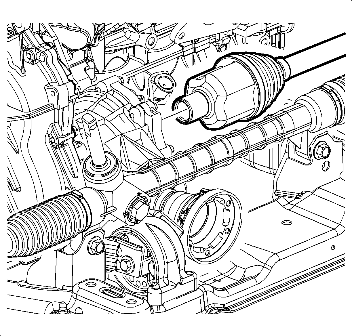
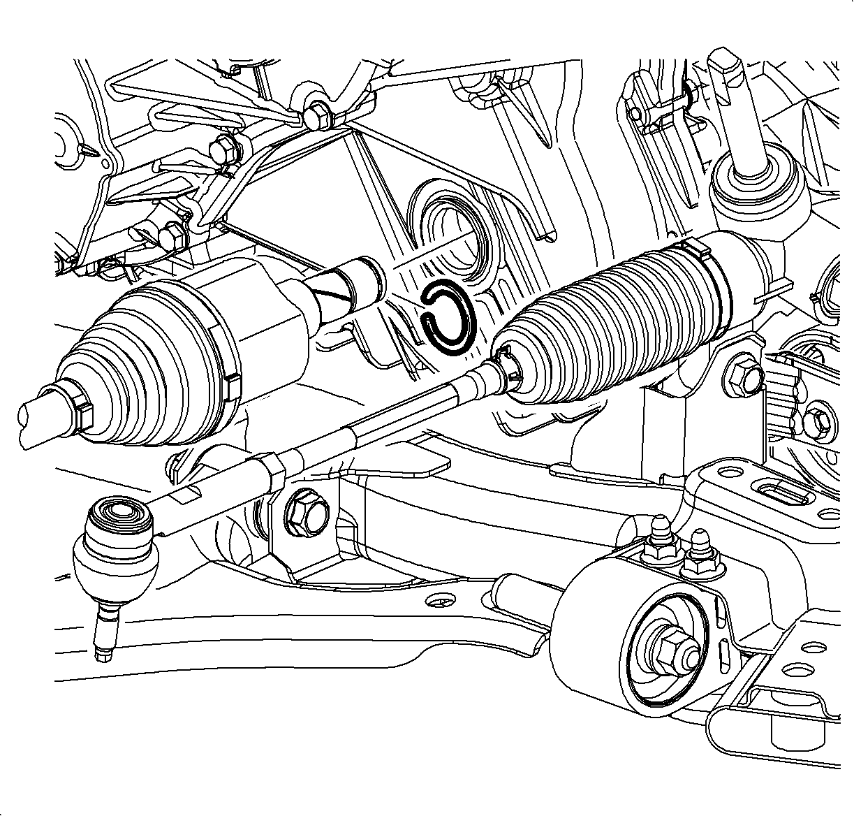

Important: Do not damage the left axle seal

Tighten
Tighten the frame-to-body bolts to 155 N·m(114 lb ft)

Tighten
Tighten the rear pitch restrictor bolt to 110 N·m(81 lb ft)

Tighten
Tighten the Front pitch restrictor bolts to 50 N·m(37 lb ft)
Tighten
Tighten the Front pitch restrictor through-bolts to 110 N·m(81 lb ft)
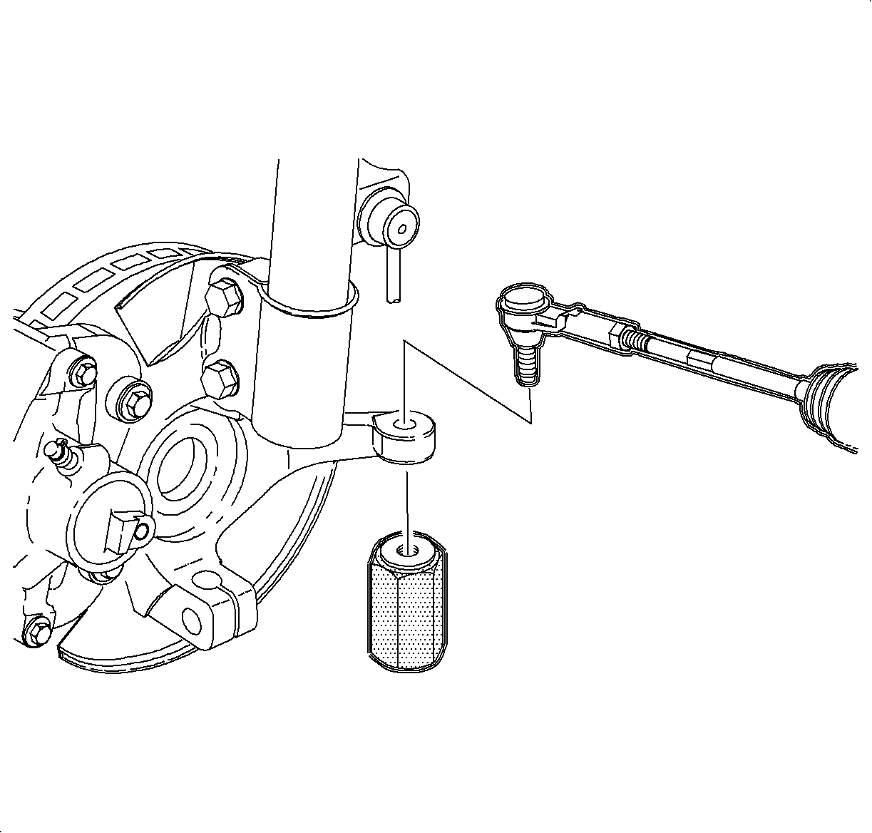
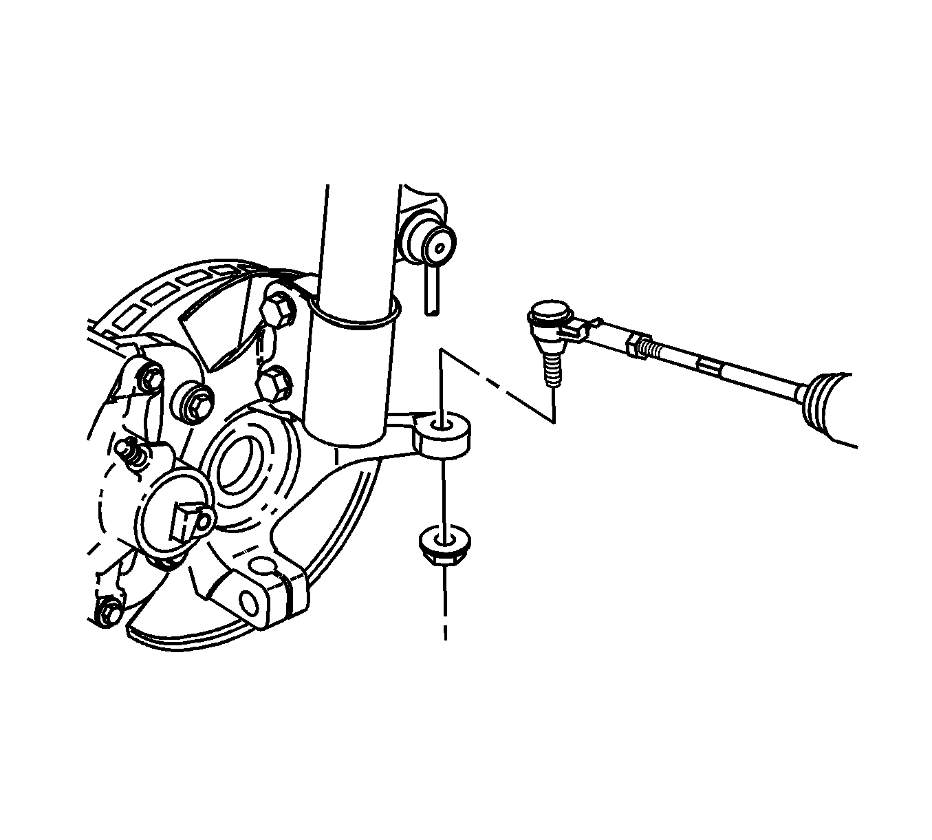
Tighten
Tighten the rod-to-knuckle nut to 50 N·m(37 lb ft)

Important: Tighten the nut one additional flat to align cotter pin hole if necessary.
Tighten
Tighten the lower control arm nut to 110 N·m(81 lb ft) plus 150 degrees.
Tighten
Tighten the rack and pinion bolts to 110 N·m(81 lb ft)

Tighten
Tighten the lower stabilizer nut to 65 N·m(48 lb ft)

Tighten
Tighten the drive shaft bolts to 25 N·m(18 lb ft)

Tighten
Tighten the transaxle cooler line nut to 7 N·m(62 lb in)


Tighten the bolts in a criss-cross pattern.
Tighten
Tighten the wheel nuts to 125 N·m(92 lb ft)

Tighten
Tighten the upper left-hand transaxle mount bolts to 50 N·m(37 lb ft)

Tighten
Tighten the fluid level indicator bolt to 12 N·m(9 lb ft)

Important: It is recommended that transmission adaptive pressure (TAP) information be reset.
Resetting the TAP values using a scan tool will erase all learned values in all cells. As a result, The ECM, PCM or TCM will need to relearn TAP values. Transmission performance may be affected as new TAP values are learned.