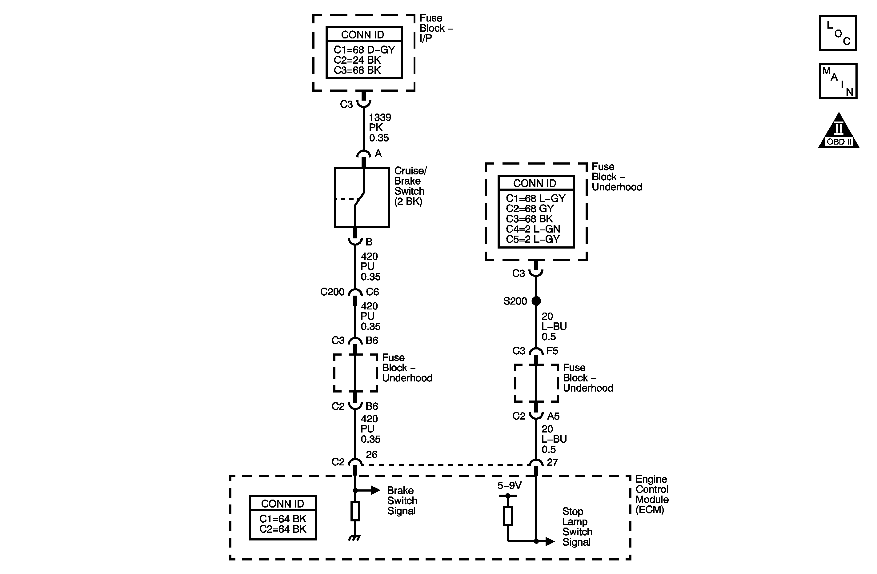
Circuit Description
The cruise/brake switch signal circuit is a normally closed switch. The stop lamp switch signal circuit is a normally open switch. When the brake pedal is released, the ECM detects a high voltage signal on the cruise/brake switch signal circuit and a low signal voltage signal on the stop lamp switch signal circuit.
Conditions for Running the DTC
| • | The ignition is ON. |
| • | The traction control system or the antilock brake system have not failed. |
Conditions for Setting the DTC
| • | When the brake pedal is released, the ECM detects a high voltage signal on the stop lamp switch signal circuit or when the ECM detects a low voltage signal on the cruise/brake switch signal circuit. |
| • | The above conditions are present for 1.5 seconds. |
Action Taken When the DTC Sets
| • | The ECM stores the DTC information into memory when the diagnostic runs and fails. |
| • | The malfunction indicator lamp (MIL) will not illuminate. |
| • | The ECM records the operating conditions at the time the diagnostic fails. The ECM stores this information in the Failure Records. |
Conditions for Clearing the DTC
| • | A last test failed, or current DTC, clears when the diagnostic runs and does not fail. |
| • | A history DTC will clear after 40 consecutive warm-up cycles, if no failures are reported by this or any other non-emission related diagnostic. |
| • | Use a scan tool in order to clear the DTC. |
Diagnostic Aids
In order to avoid a misdiagnosis, perform the following:
| • | Inspect for proper operation of the stop lamps. Refer to Exterior Lighting Systems Description and Operation in Lighting Systems. |
| • | Inspect for proper adjustment of the stop lamps. Refer to Stop Lamp Switch Adjustment in Lighting Systems. |
| • | Inspect for proper adjustment of the cruise control release switch. Refer to Cruise Release Switch Adjustment . |
| • | For an intermittent condition, refer to Testing for Intermittent Conditions and Poor Connections in Wiring Systems. |
Step | Action | Yes | No |
|---|---|---|---|
Schematic Reference: Cruise Control Schematics Connector End View Reference: Cruise Control Connector End Views or Lighting Systems Connector End Views in Lighting Systems | |||
1 | Did you perform the Cruise Control Diagnostic System Check? | Go to Step 2 | |
2 |
Does the test lamp illuminate? | Go to Step 3 | Go to Step 4 |
3 | Test the stop lamp switch signal circuit for a short to voltage. Refer Circuit Testing and to Wiring Repairs in Wiring Systems. Did you find and correct the condition? | Go to Step 9 | Go to Step 6 |
4 | Test the cruise/brake switch signal circuit for a an open or for a high resistance. Refer Circuit Testing and to Wiring Repairs in Wiring Systems. Did you find and correct the condition? | Go to Step 9 | Go to Step 5 |
5 | Inspect for poor connections at the harness connector of the cruise release switch. Refer to Testing for Intermittent Conditions and Poor Connections and to Connector Repairs in Wiring Systems. Did you find and correct the condition? | Go to Step 9 | Go to Step 7 |
6 | Inspect for poor connections at the harness connector of the ECM. Refer to Testing for Intermittent Conditions and Poor Connections and to Connector Repairs in Wiring Systems. Did you find and correct the condition? | Go to Step 9 | Go to Step 8 |
7 | Replace the cruise release switch. Refer to Cruise Control Release Switch Replacement . Did you complete the repair? | Go to Step 9 | -- |
8 |
Important: Program the replacement ECM. Replace the ECM. Refer to Engine Control Module Replacement in Engine Controls-2.2 L. Did you complete the replacement? | Go to Step 9 | -- |
9 |
Does the DTC reset? | Go to Step 2 | System OK |
