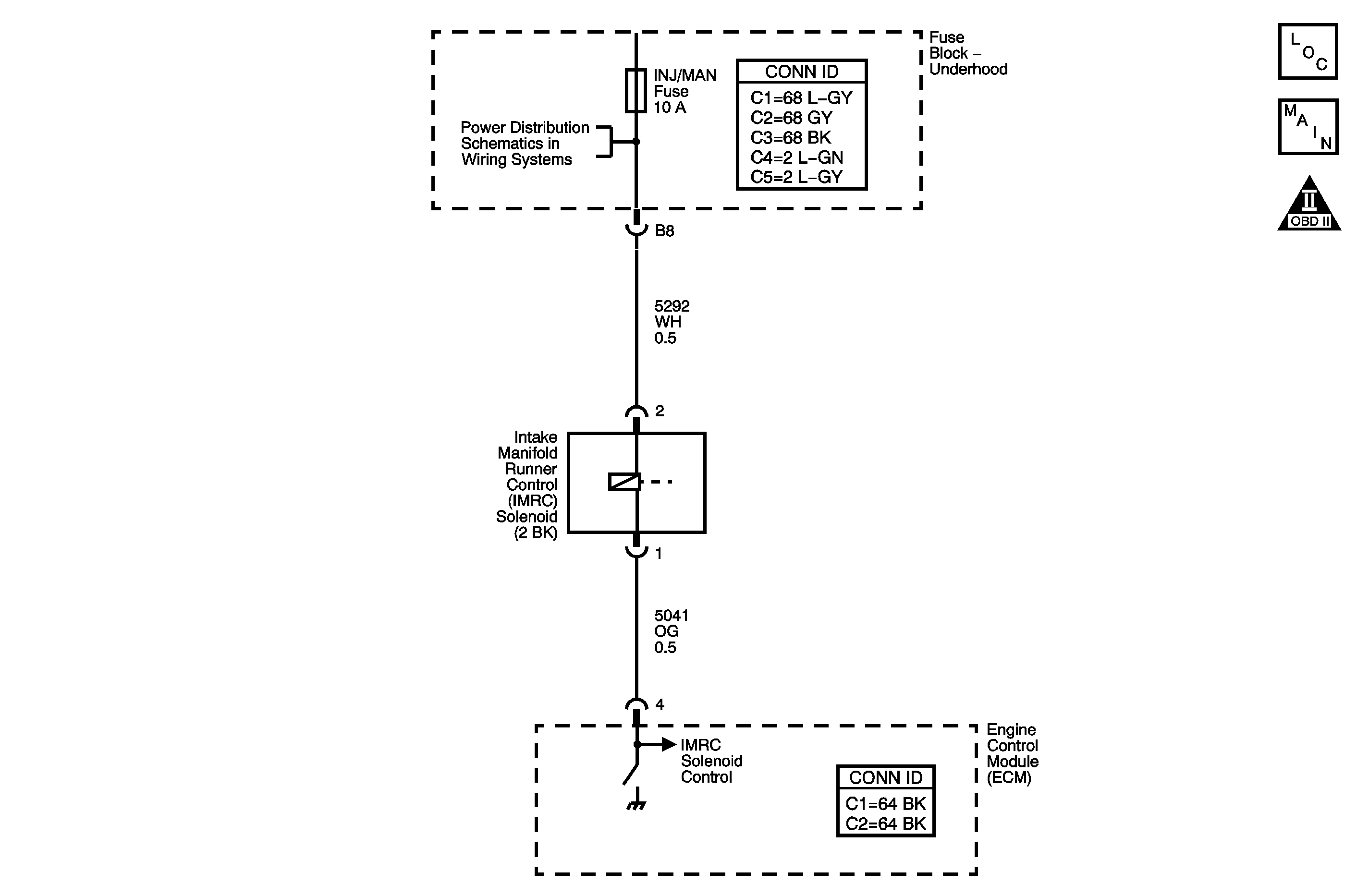
Circuit Description
The intake manifold upper plenum is divided into two separate runners by an intake manifold runner control (IMRC) valve. During low speed, high load conditions the IMRC valve is closed creating a longer runner path inside the plenum which increases torque. During higher engine speeds the IMRC valve opens creating a shorter runner path inside the plenum which increases horsepower. The IMRC valve is controlled by an IMRC vacuum solenoid. Manifold vacuum is supplied to the IMRC solenoid. A 12-volt supply from the manifold fuse to the IMRC solenoid is applied when the ignition key is turned ON. The solenoid is normally closed, which will not allow vacuum to pass through it. When the engine speed and load are increased above a calibrated threshold, the engine control module (ECM) provides a ground to the solenoid, energizing the solenoid and allowing vacuum to be applied to the IMRC valve. When the IMRC solenoid is commanded OFF, the voltage of the control circuit is high, battery voltage. When the IMRC solenoid is commanded ON, the voltage of the control circuit is low, near 0 volts. The ECM applies a pull up voltage of 2.6-4.6 volts on the control circuit to differentiate between an open, a short to ground, or a short to voltage. If the ECM detects a voltage that is more than what it should be when the IMRC solenoid is commanded ON, DTC P2010 sets.
Conditions for Running the DTC
| • | The engine speed is more than 40 RPM. |
| • | The engine is running. |
| • | The battery voltage is more than 8 volts and less than 18 volts. |
Conditions for Setting the DTC
The ECM detects that the IMRC solenoid feedback voltage is more than 4.6 volts when the IMRC solenoid is commanded ON for more than 0.5 second.
Action Taken When the DTC Sets
| • | The control module stores the DTC information into memory when the diagnostic runs and fails. |
| • | The malfunction indicator lamp (MIL) will not illuminate. |
| • | The control module records the operating conditions at the time the diagnostic fails. The control module stores this information in the Failure Records. |
| • | The driver information center, if equipped, may display a message. |
Conditions for Clearing the DTC
| • | A current DTC Last Test Failed clears when the diagnostic runs and passes. |
| • | A history DTC clears after 40 consecutive warm-up cycles, if no failures are reported by this or any other non-emission related diagnostic. |
| • | Clear the DTC with a scan tool. |
Step | Action | Yes | No |
|---|---|---|---|
Schematic Reference: Engine Controls Schematics Connector End View Reference: Engine Control Module Connector End Views or Engine Controls Connector End Views | |||
1 | Did you perform the Diagnostic System Check-Engine Controls? | Go to Step 2 | |
2 |
Does the IMRC solenoid click with each command? | Go to Step 3 | Go to Step 4 |
3 |
Did the DTC fail this ignition? | Go to Step 4 | Go to Intermittent Conditions |
4 |
Does the test lamp turn ON and OFF? | Go to Step 6 | Go to Step 5 |
5 | Test the control circuit of the IMRC solenoid for a short to voltage. Refer to Circuit Testing and Wiring Repairs in Wiring Systems. Did you find and correct the condition? | Go to Step 10 | Go to Step 7 |
6 | Test for an intermittent and for a poor connection at the IMRC solenoid. Refer to Testing for Intermittent Conditions and Poor Connections and Connector Repairs in Wiring Systems. Did you find and correct the condition? | Go to Step 10 | Go to Step 8 |
7 | Test for an intermittent and for a poor connection at the harness connector of the engine control module (ECM). Refer to Testing for Intermittent Conditions and Poor Connections and Connector Repairs in Wiring Systems. Did you find and correct the condition? | Go to Step 10 | Go to Step 9 |
8 | Replace the IMRC solenoid. Refer to Intake Manifold Runner Control Solenoid Replacement . Did you complete the replacement? | Go to Step 10 | -- |
9 | Replace the ECM. Refer to Engine Control Module Replacement . Did you complete the replacement? | Go to Step 10 | -- |
10 |
Did the DTC fail this ignition? | Go to Step 2 | Go to Step 11 |
11 | Observe the Capture Info with a scan tool. Are there any DTCs that have not been diagnosed? | System OK | |
