Tools Required
| • | J 36346 Fascia Retainer Remover |
| • | J 44810 Transaxle Range Switch Alignment |
Removal Procedure
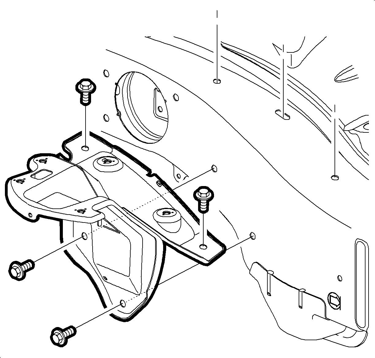
- Remove the battery. Refer to Battery Replacement .
- Loosen the battery tray bracket screws and remove the battery tray bracket.
- Apply the parking brake and place the control shift lever in (N) Neutral.
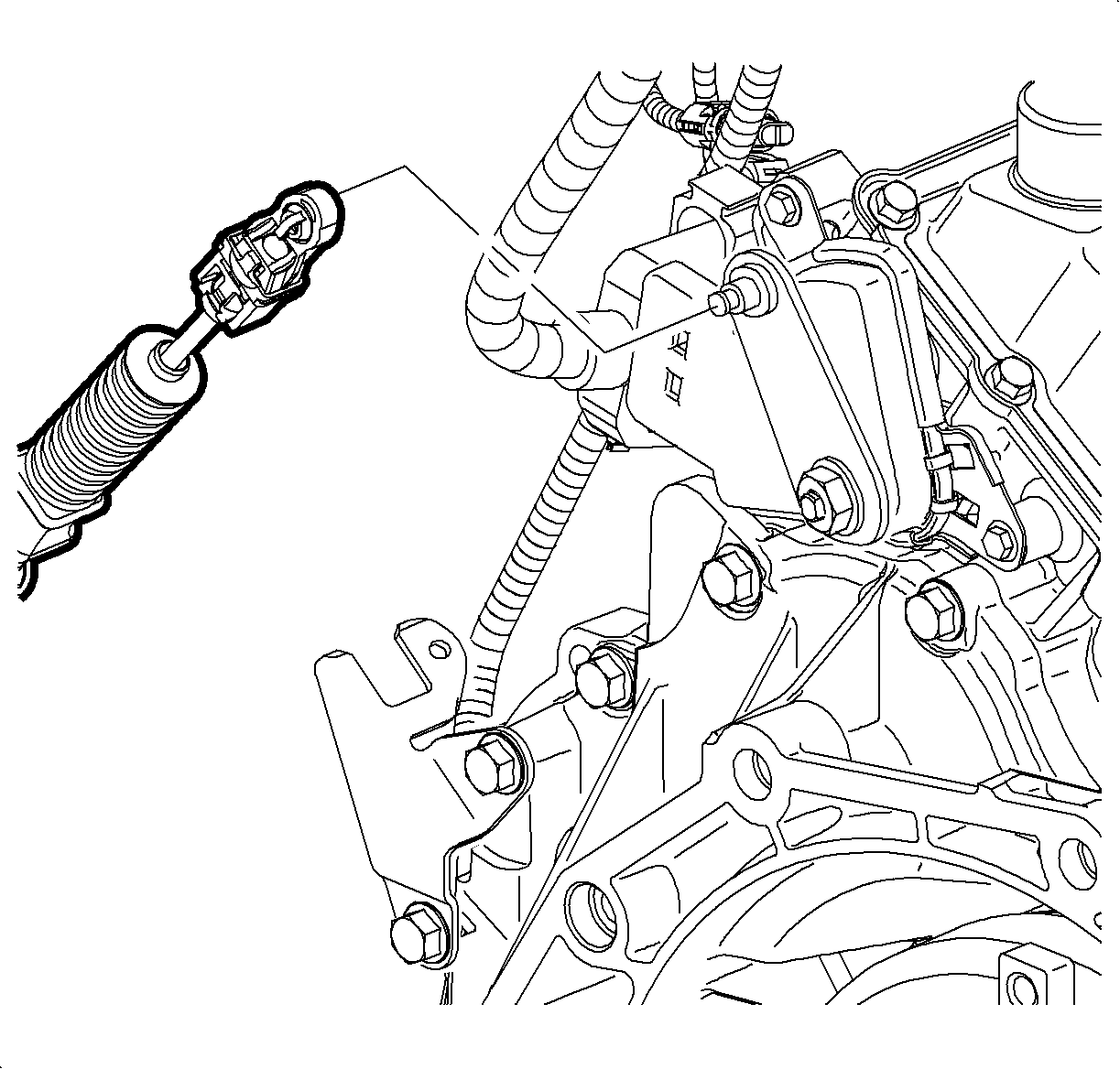
- Using the Fascia Retainer Remover J 36346 , remove the control cable assembly from the transaxle range switch lever.
- Disconnect the electrical connectors from the transaxle range switch.
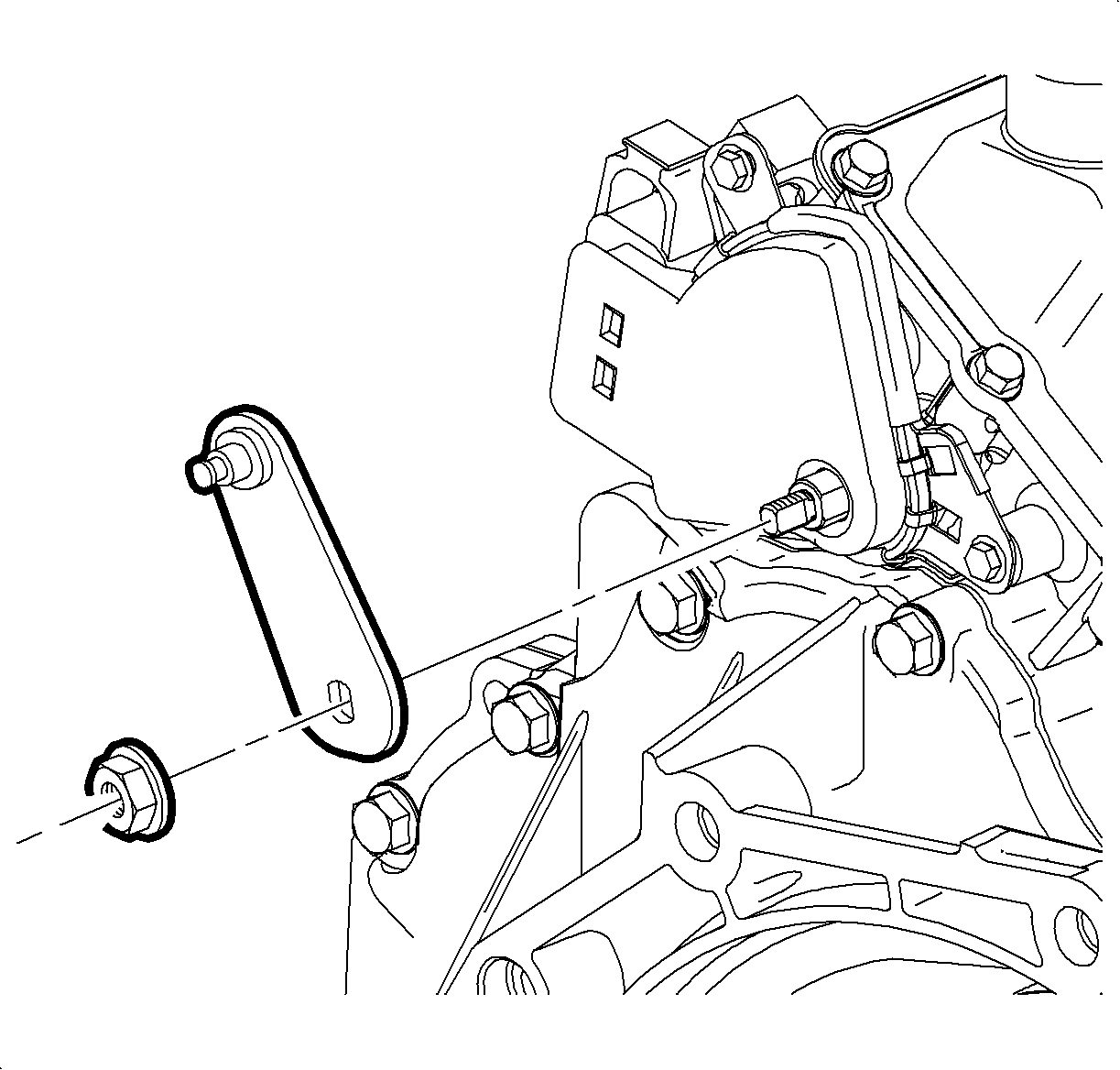
- Remove the transaxle range switch lever nut and lever.
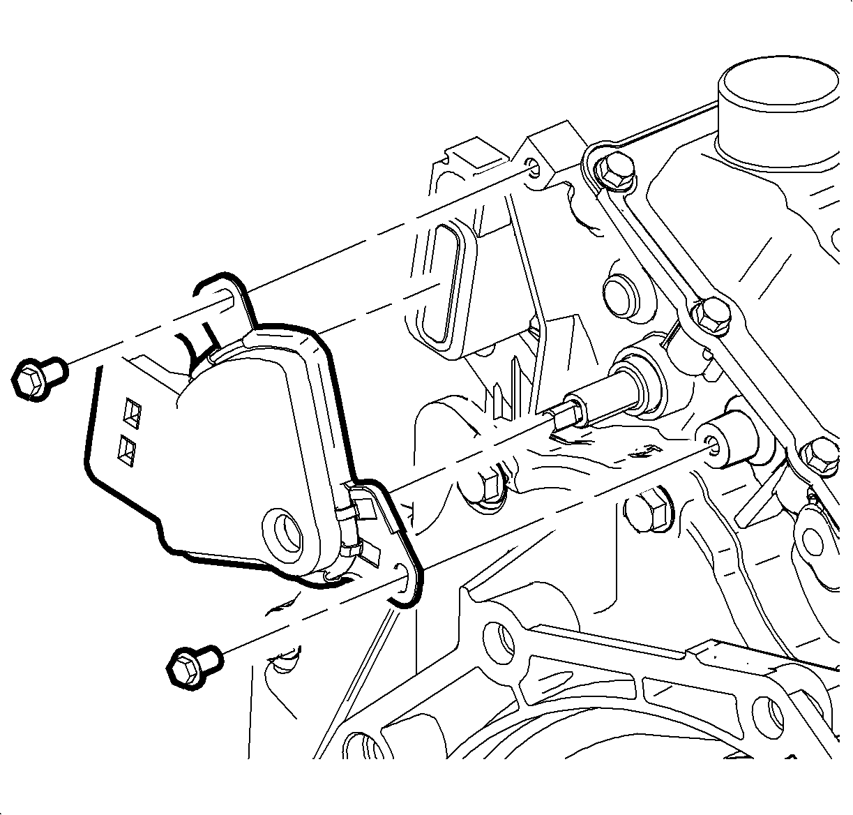
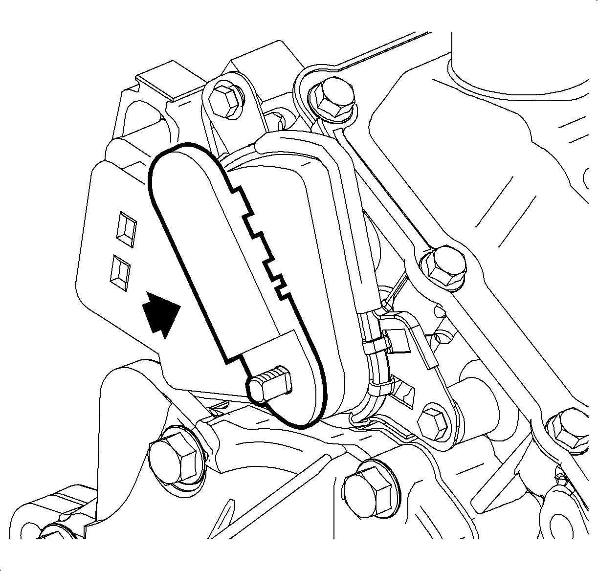
- Remove the transaxle range switch bolts and remove the switch.
Caution: Do not tip the battery over a 45 degree angle or acid could spill causing serious personal injury.
Important: Record all pre-set radio stations.
Important: The transaxle manual shaft must be in (N) Neutral position prior to re-installing the range switch.
Installation Procedure
(USING OLD SWITCH)
- Make sure the transaxle manual shaft is in (N) Neutral position.
- Align the flats on the transaxle shift shaft with the flats on the transaxle range switch and install the switch.
- Loosely install the transaxle range switch bolts.
- Insert the Transaxle Range Switch AlignmentJ 44810 as shown and rotate the switch until the tool drops into position. The switch is aligned when the pin on the tool drops into the hole on the transaxle range switch.
- Tighten the transaxle range switch bolts.
- Remove the alignment tool.
- Install the transaxle range switch lever and nut.
- Connect the transaxle range switch electrical connectors.
- Install the control cable assembly to the transaxle range switch lever and verify proper operation.
- Install the battery tray bracket.
- Position the battery tray bracket and tighten the screws.
- Install the battery. Refer to Battery Replacement .
- After adjusting the switch, verify the engine only starts in (P) Park or (N) Neutral. Using the scan tool, monitor the TR Sw. to verify the selected position matches the scan tool. Move the selector through all positions. If the engine starts in any other position, readjust the switch.

Notice: Refer to Fastener Notice in the Preface section.
Tighten
Tighten the transaxle range switch bolts to 11 N·m
(8 lb ft).

Tighten
Tighten the transaxle range switch lever nut to
16 N·m (12 lb ft).

Tighten
Tighten the battery tray bracket screws to 16 N·m
(12 lb ft).
Installation Procedure
(USING NEW SWITCH)
- Make sure the transaxle manual shaft is in (N) Neutral position.
- Align the flats on the transaxle shift shaft with the flats on the transaxle range switch and install the switch.
- Tighten the transaxle range switch bolts.
- Install the transaxle range switch lever and nut.
- Connect the transaxle range switch electrical connectors.
- Install the control cable assembly to the transaxle range switch lever.
- Install the battery tray bracket.
- Position the battery tray bracket and tighten the screws.
- Install the battery. Refer to Battery Replacement .
- Insert the battery and tighten the battery hold-down screw.
- After adjusting the switch, verify the engine only starts in (P) Park or (N) Neutral. Using the scan tool, monitor the TR Sw. to verify the selected position matches the scan tool. Move the selector through all positions. If the engine starts in any other position, readjust the switch.

Tighten
Tighten the transaxle range switch bolts to 11 N·m
(8 lb ft).

Tighten
Tighten the transaxle range switch lever nut to
16 N·m (12 lb ft).


Tighten
Tighten the battery tray bracket screws to 16 N·m
(12 lb ft).
Tighten
Tighten the battery hold-down screw to 15 N·m
(11 lb ft).
