GM Service Manual Online
For 1990-2009 cars only
Figure 1:

Power, Ground, MIL, and PCM Communication
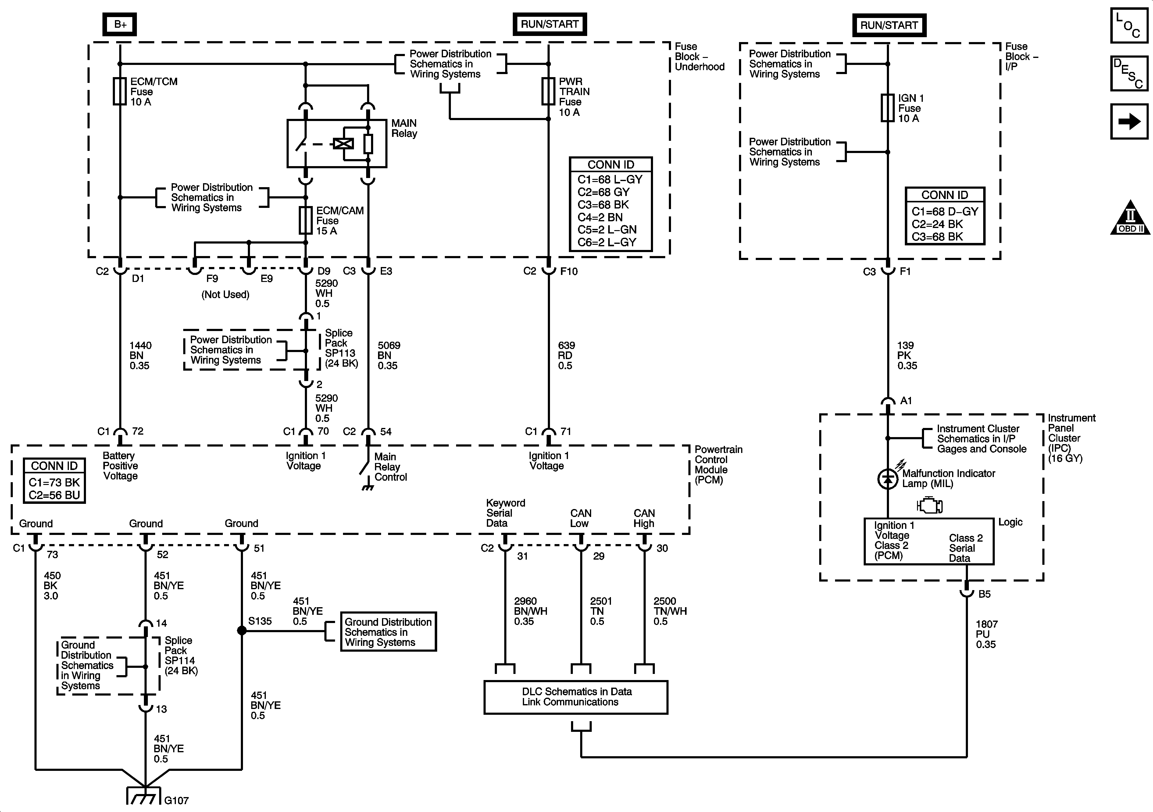

Object Number: 1241222  Size: FS
Master Electrical Component List
Powertrain Control Module Description
Engine Data Sensors - 5 Volt References
OBD II Symbol Description Notice
Battery, Starter, Generator, PSCM, and the B+ Circuits to the Underhood Fuse Block
IGN Fuse, Ignition Switch, and the Igntion Switch Position Circuits
IGN 1, BCM(IGN), AIR BAG, EPS, and CRUISE Fuses (I/P Fuse Block)
IGN Fuse, Ignition Switch, and the Igntion Switch Position Circuits
PWR WDW Relay, PWR WDW, SUNROOF, ABS, ABS PWR, HVAC BLOWER, AUX 1 OUTLET, CIGAR/AUX 2, and ECM/TCM Fuses
L66 2 of 2-ECM/CAM Fuse
w/L66 - G103, G105, G107, G109, and G207
DLC Schematic
Indicators and MIL
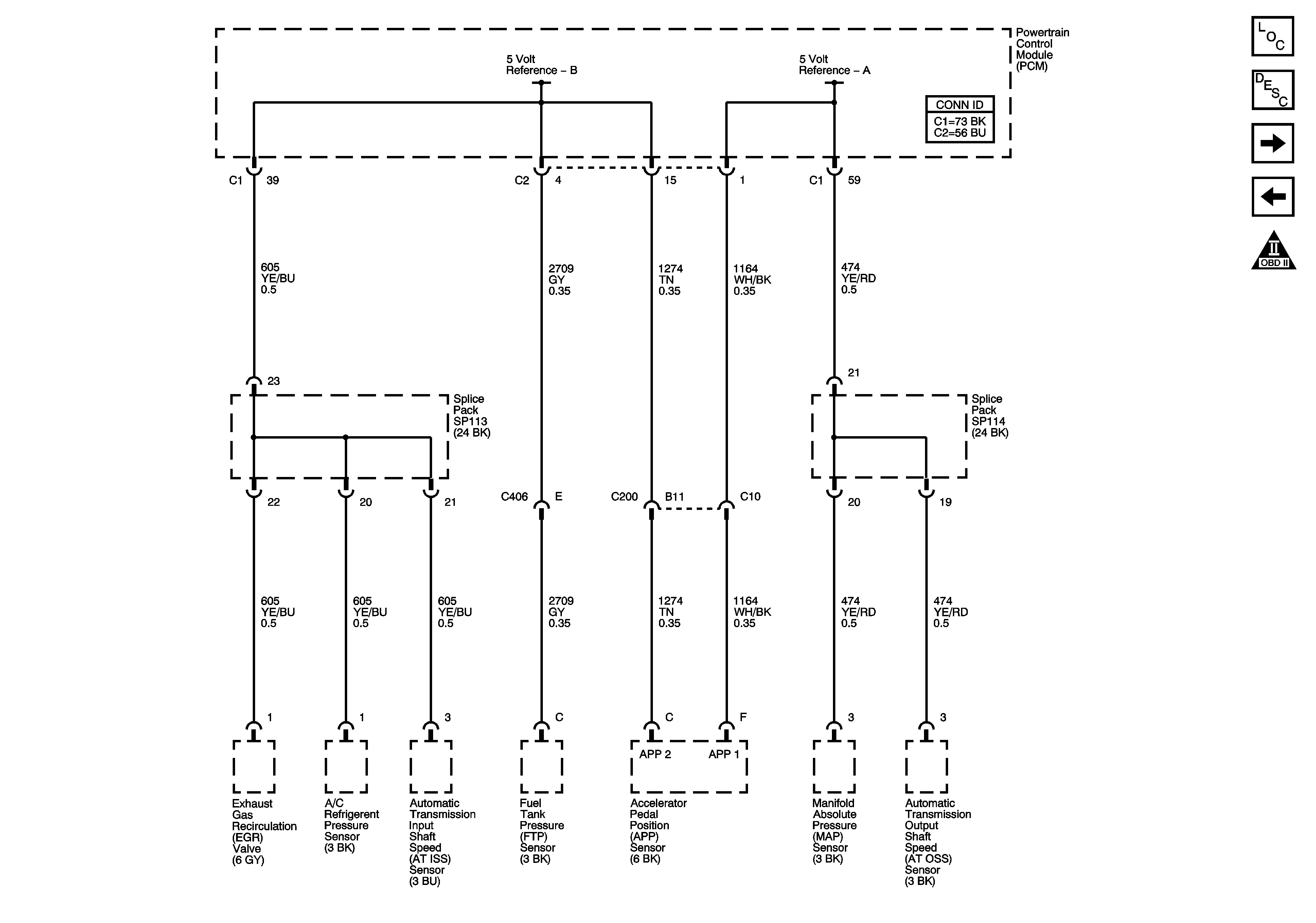
Figure 2:

Engine Data Sensors - 5-Volt References

Object Number: 1241223  Size: FS
Master Electrical Component List
Powertrain Control Module Description
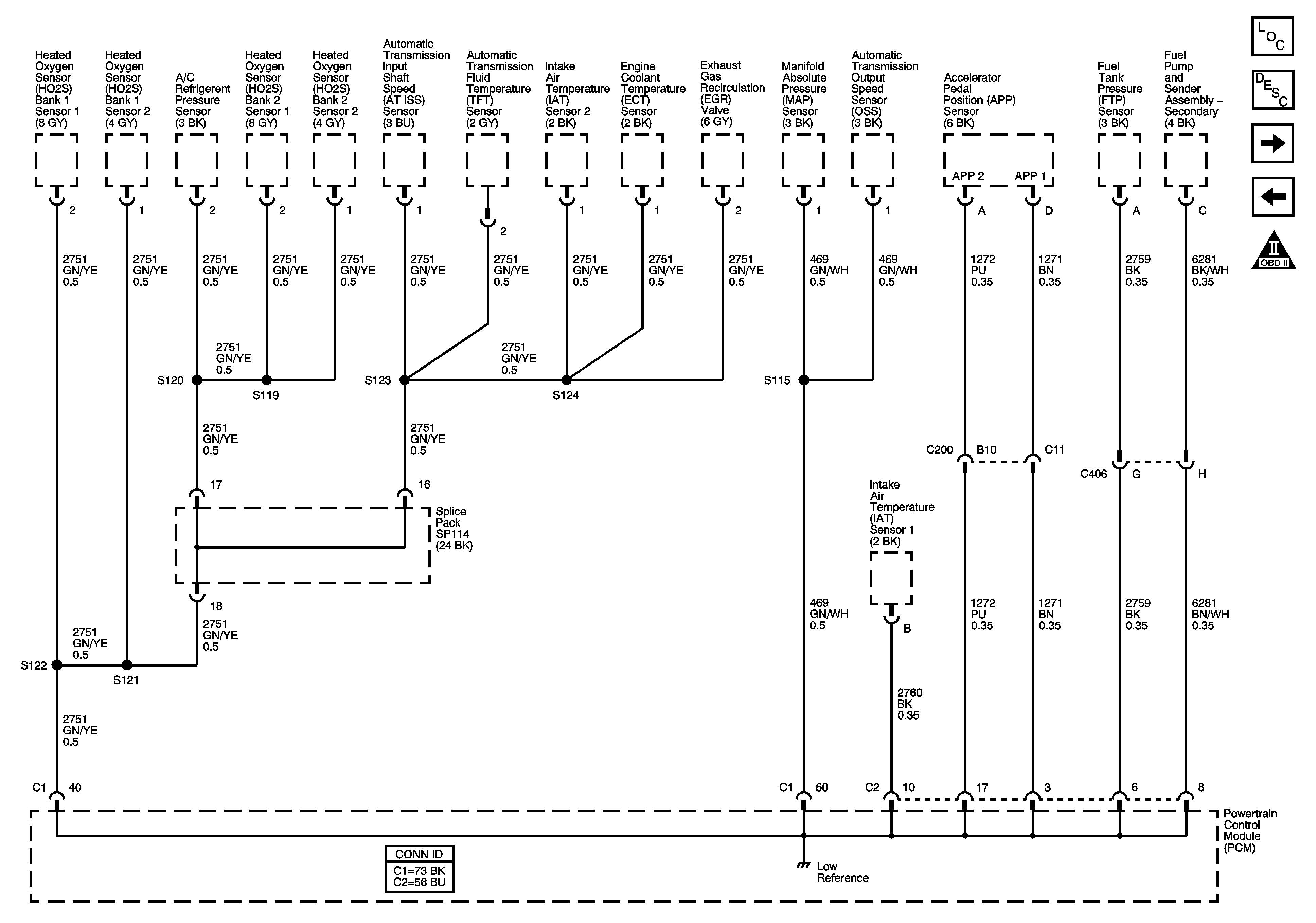
Engine Data Sensors - Low References
Power, Ground, MIL, and Communication
OBD II Symbol Description Notice
Figure 3:

Engine Data Sensors - Low References


Object Number: 1241224  Size: FS
Master Electrical Component List
Powertrain Control Module Description
IAT, ECT, MAP Sensors, and the Stop Lamp Switch Signal
Engine Data Sensors - 5 Volt References
OBD II Symbol Description Notice
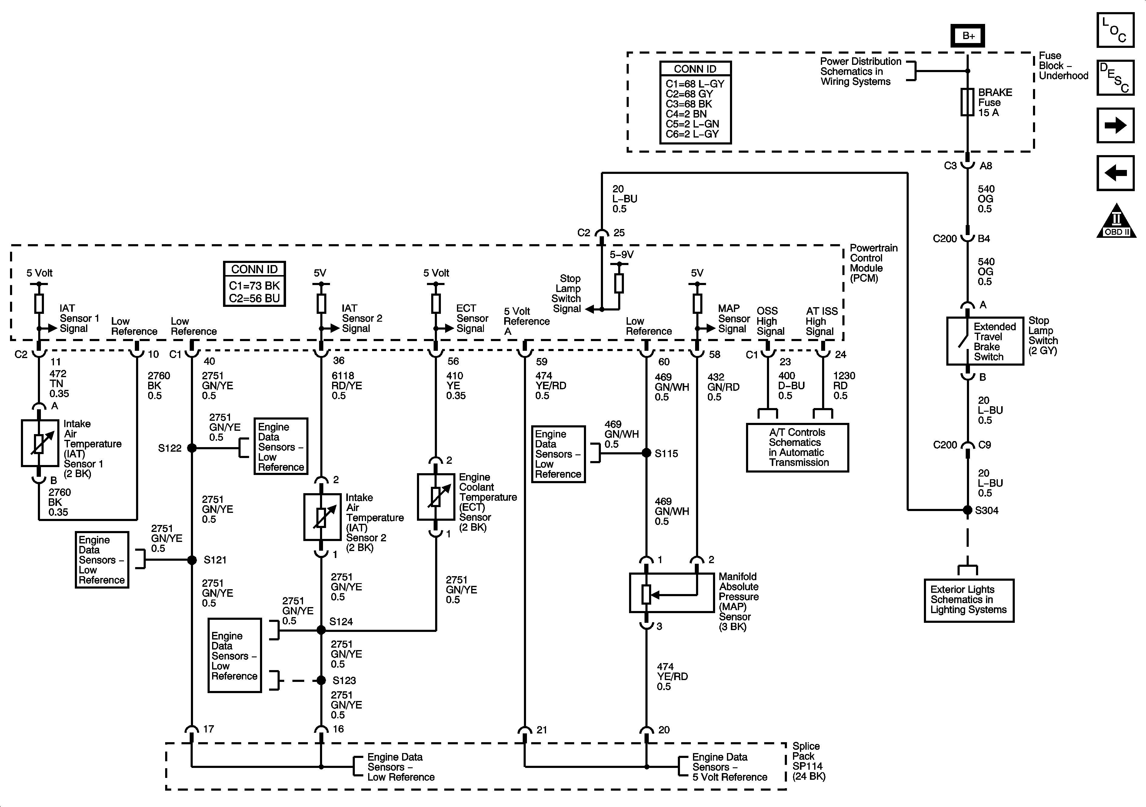
Figure 4:

IAT, ECT, and MAP Sensors, and Stop Lamp Switch Signal

Object Number: 1241225  Size: FS
Master Electrical Component List
Air Intake System Description
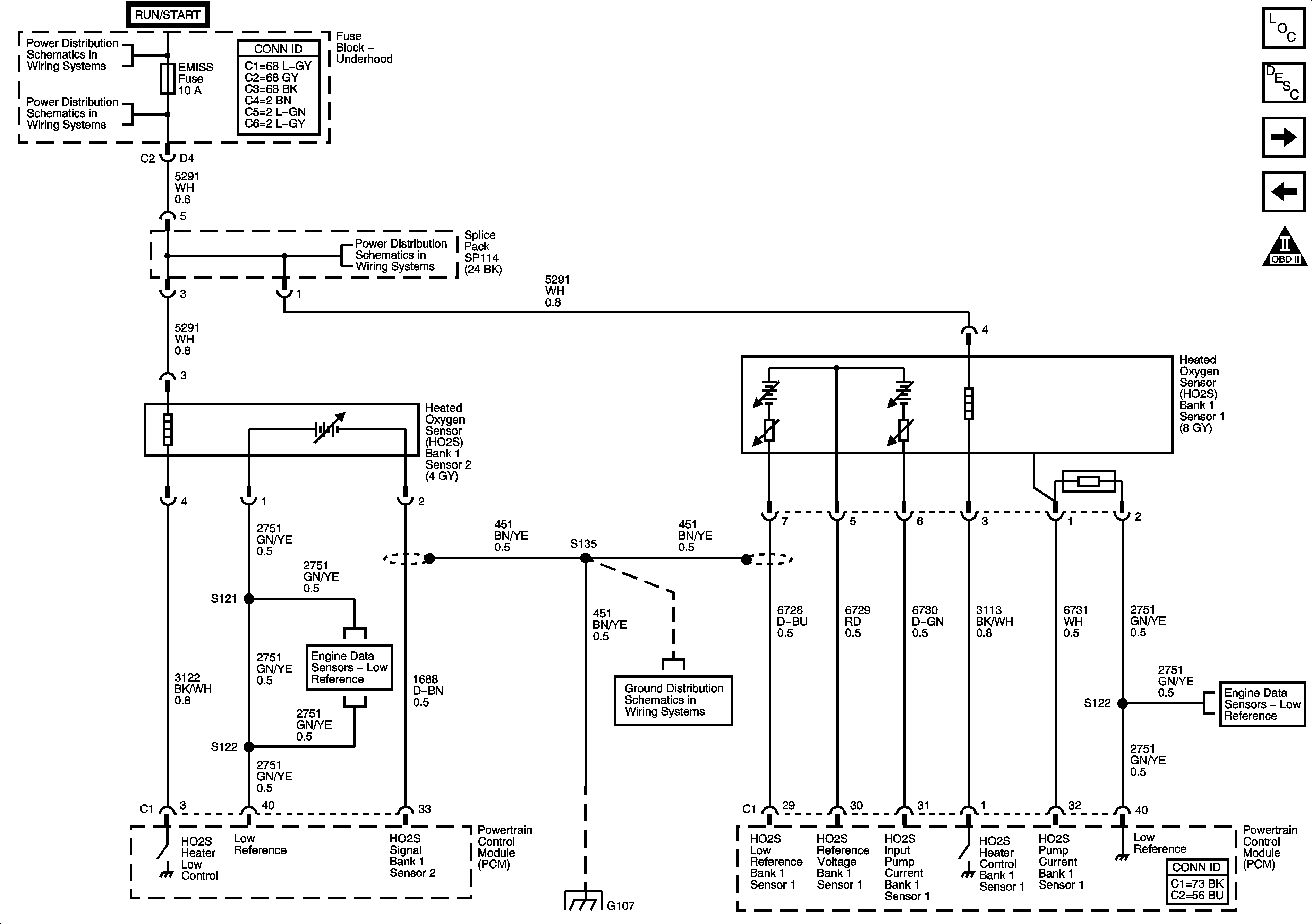
Bank 1 Oxygen Sensors
Engine Data Sensors - Low References
OBD II Symbol Description Notice
Battery, Starter, Generator, PSCM, and the B+ Circuits to the Underhood Fuse Block
Stop Lamps
Power, Ground, PNP Switch, and Communication Data
Engine Data Sensors - Low References
Engine Data Sensors - 5 Volt References
Figure 5:

Bank 1 Oxygen Sensors


Object Number: 1241226  Size: FS
Master Electrical Component List
Powertrain Control Module Description
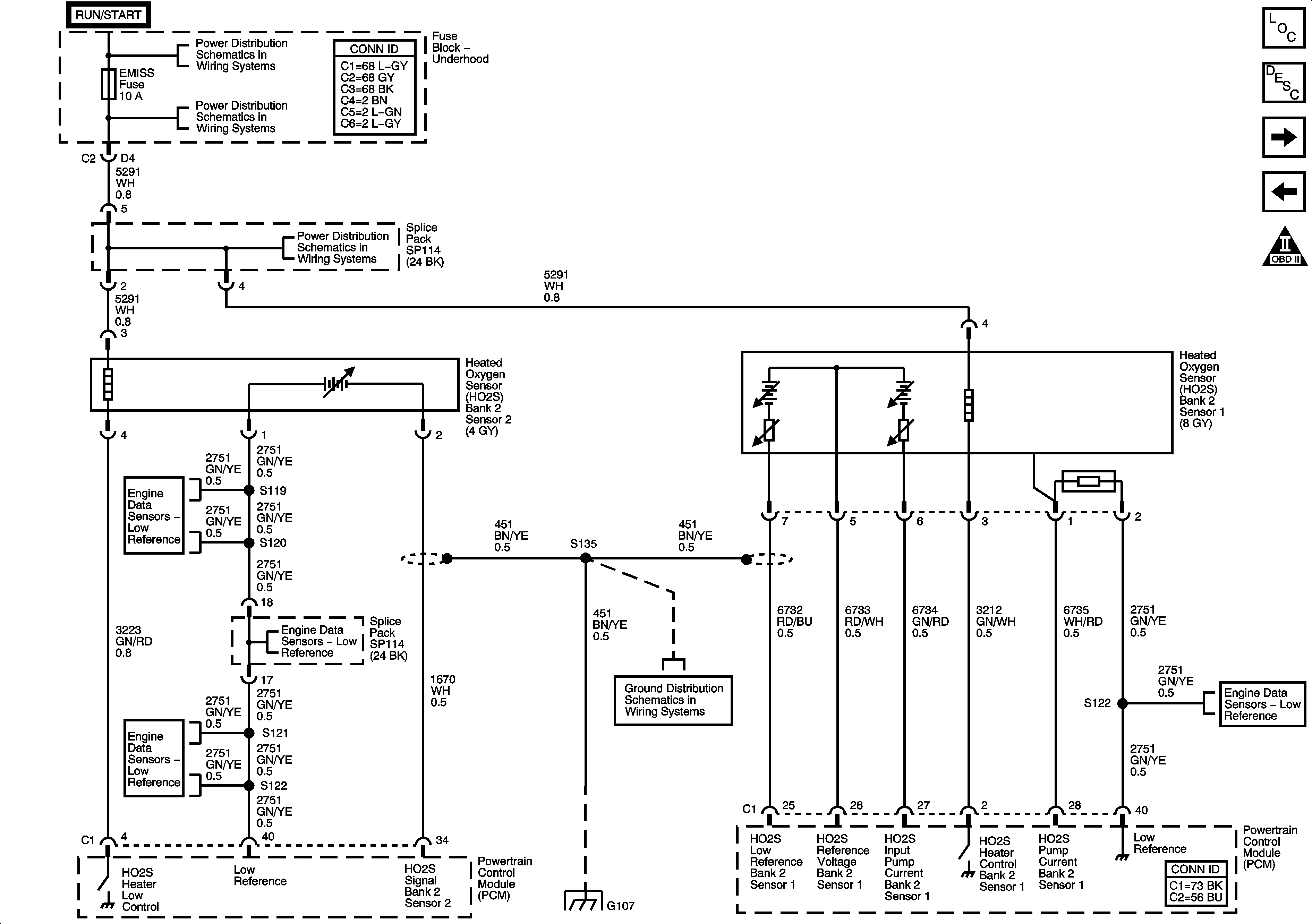
Bank 2 Oxygen Sensors
IAT, ECT, MAP Sensors, and the Stop Lamp Switch Signal
OBD II Symbol Description Notice
IGN Fuse, Ignition Switch, and the Igntion Switch Position Circuits
L66 1 of 2 - ENG MAIN Relay, EMISS Fuse, and the INJECTORS Fuse
Engine Data Sensors - Low References
w/L66 - G103, G105, G107, G109, and G207
Engine Data Sensors - Low References
Figure 6:

Bank 2 Oxygen Sensors


Object Number: 1241227  Size: FS
Master Electrical Component List
Powertrain Control Module Description
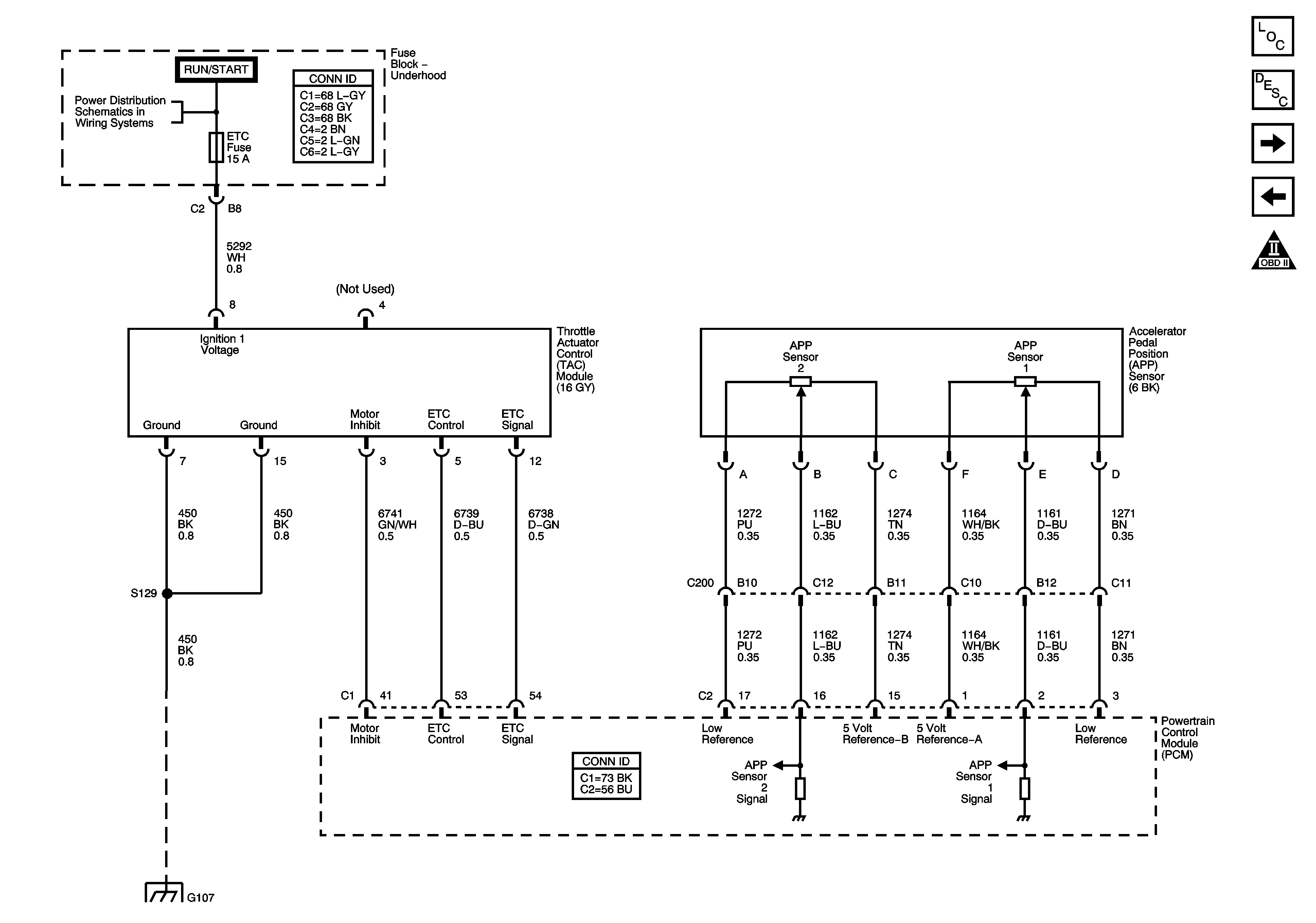
Throttle Controls
Bank 1 Oxygen Sensors
OBD II Symbol Description Notice
IGN Fuse, Ignition Switch, and the Igntion Switch Position Circuits
L66 1 of 2 - ENG MAIN Relay, EMISS Fuse, and the INJECTORS Fuse
Engine Data Sensors - Low References
w/L66 - G103, G105, G107, G109, and G207
Engine Data Sensors - Low References
Figure 7:

Throttle Controls


Object Number: 1241229  Size: FS
Master Electrical Component List
Throttle Actuator Control (TAC) System Description
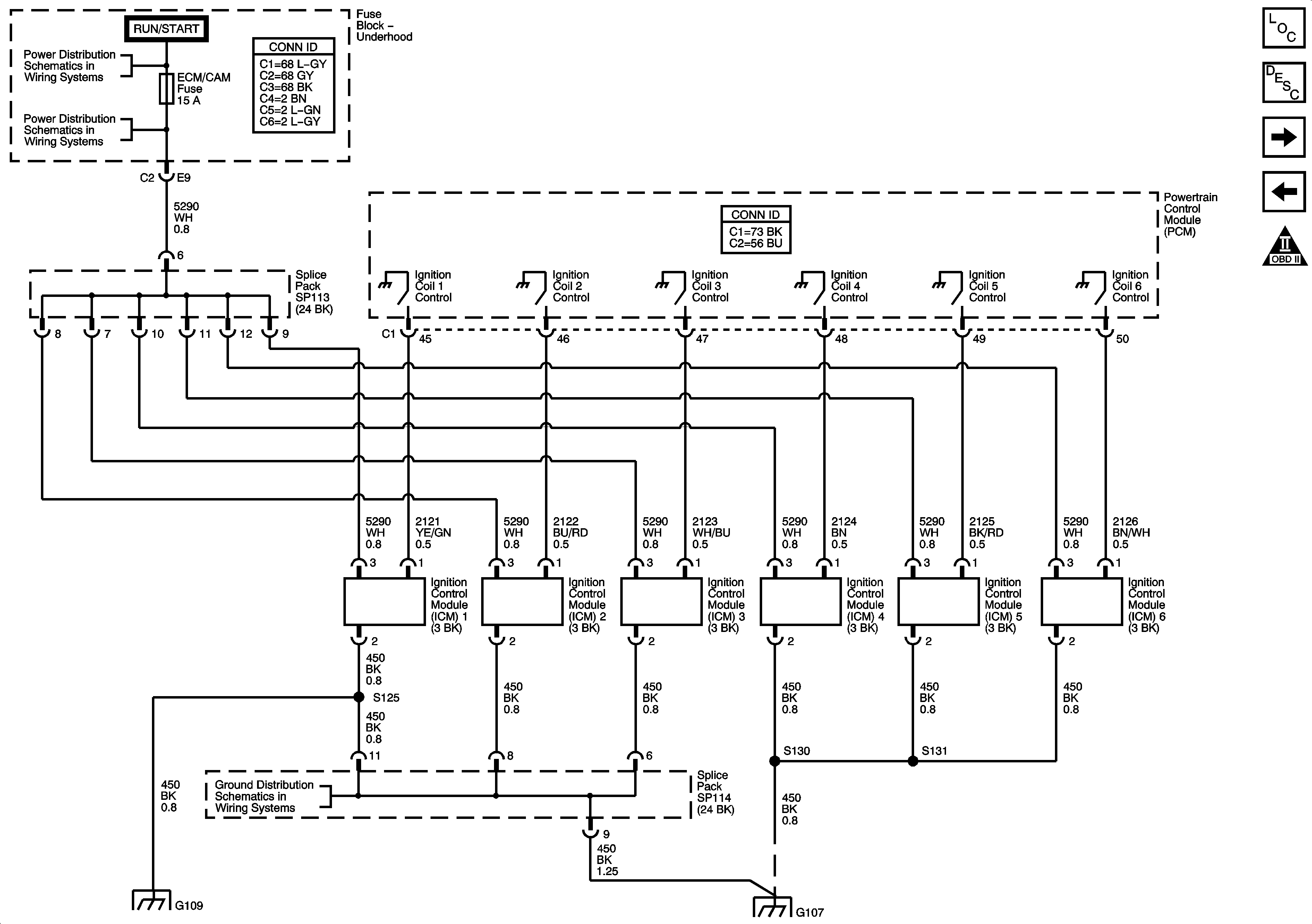
Ignition Control Modules
Bank 2 Oxygen Sensors
OBD II Symbol Description Notice
IGN Fuse, Ignition Switch, and the Igntion Switch Position Circuits
Figure 8:

Ignition Controls


Object Number: 1241231  Size: FS
Master Electrical Component List
Electronic Ignition (EI) System Description
Igntion Controls - Sensors
Throttle Controls
OBD II Symbol Description Notice
IGN Fuse, Ignition Switch, and the Igntion Switch Position Circuits
L66 1 of 2 - ENG MAIN Relay, EMISS Fuse, and the INJECTORS Fuse
w/L66 - G103, G105, G107, G109, and G207
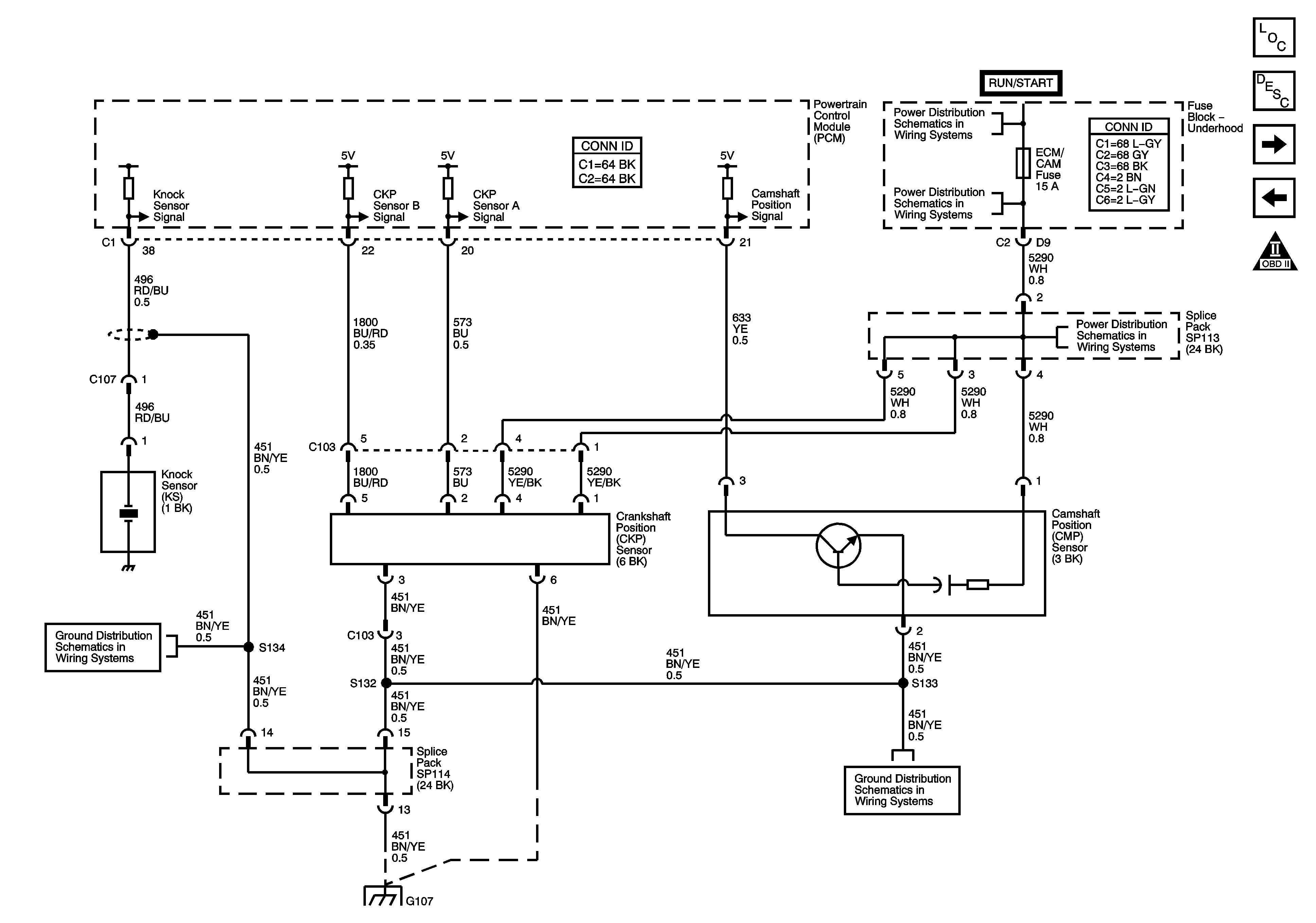
Figure 9:

Ignition Controls - Sensors


Object Number: 1241233  Size: FS
Master Electrical Component List
Electronic Ignition (EI) System Description
Fuel Injectors, Fuel Pump, and Valve Timing Signals
Ignition Control Modules
OBD II Symbol Description Notice
IGN Fuse, Ignition Switch, and the Igntion Switch Position Circuits
L66 2 of 2-ECM/CAM Fuse
w/L66 - G103, G105, G107, G109, and G207
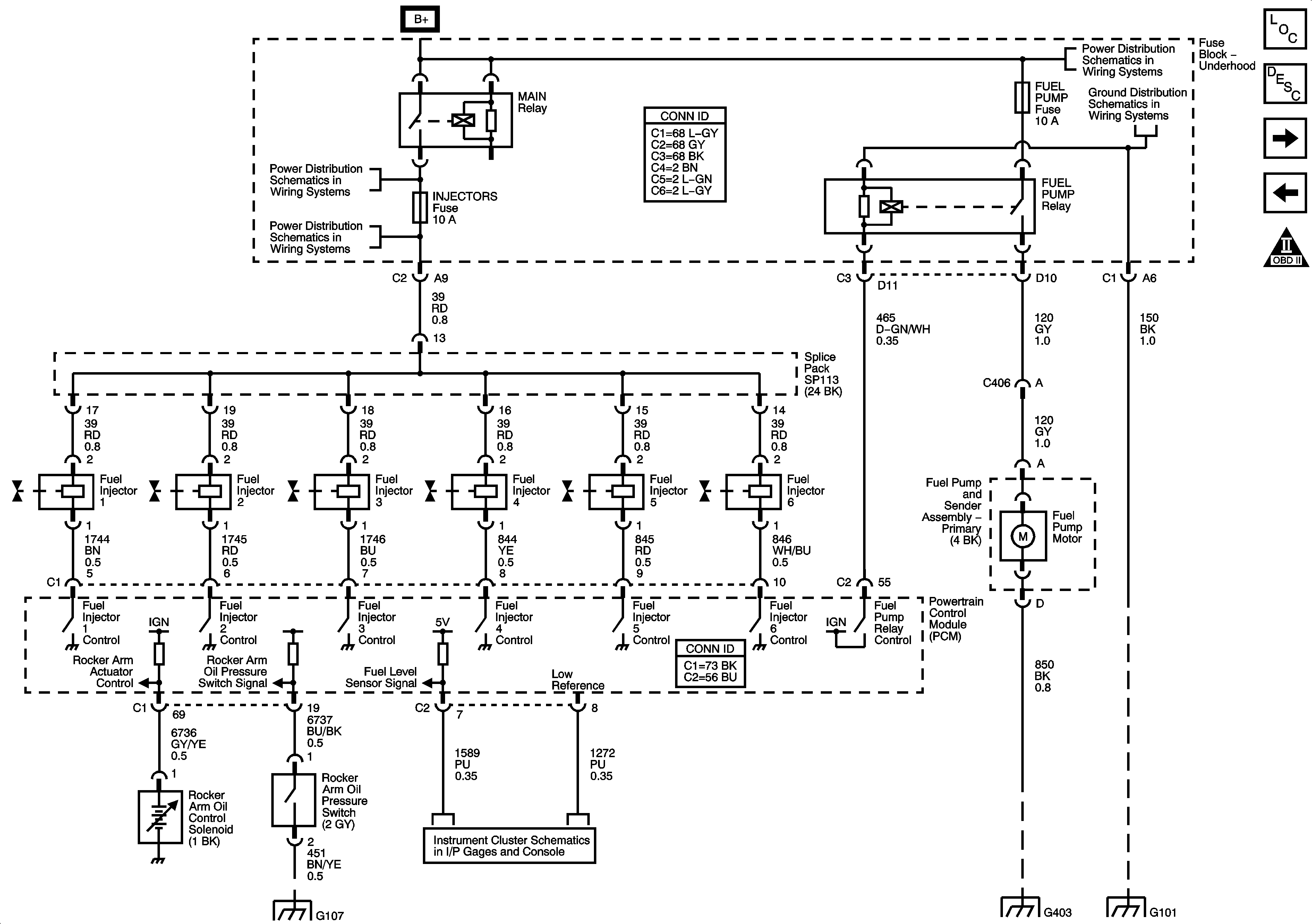
Figure 10:

Fuel Controls and Rocker Arm Oil Switch and Solenoid Controls

Object Number: 1241235  Size: FS
Master Electrical Component List
Fuel System Description
EVAP Controls, EGR and FTP Sensors
Igntion Controls - Sensors
OBD II Symbol Description Notice
IGN Fuse, Ignition Switch, and the Igntion Switch Position Circuits
L66 1 of 2 - ENG MAIN Relay, EMISS Fuse, and the INJECTORS Fuse
Battery, Starter, Generator, PSCM, and the B+ Circuits to the Underhood Fuse Block
G101
w/L66 - G103, G105, G107, G109, and G207
Gages
G401 and G403
G101
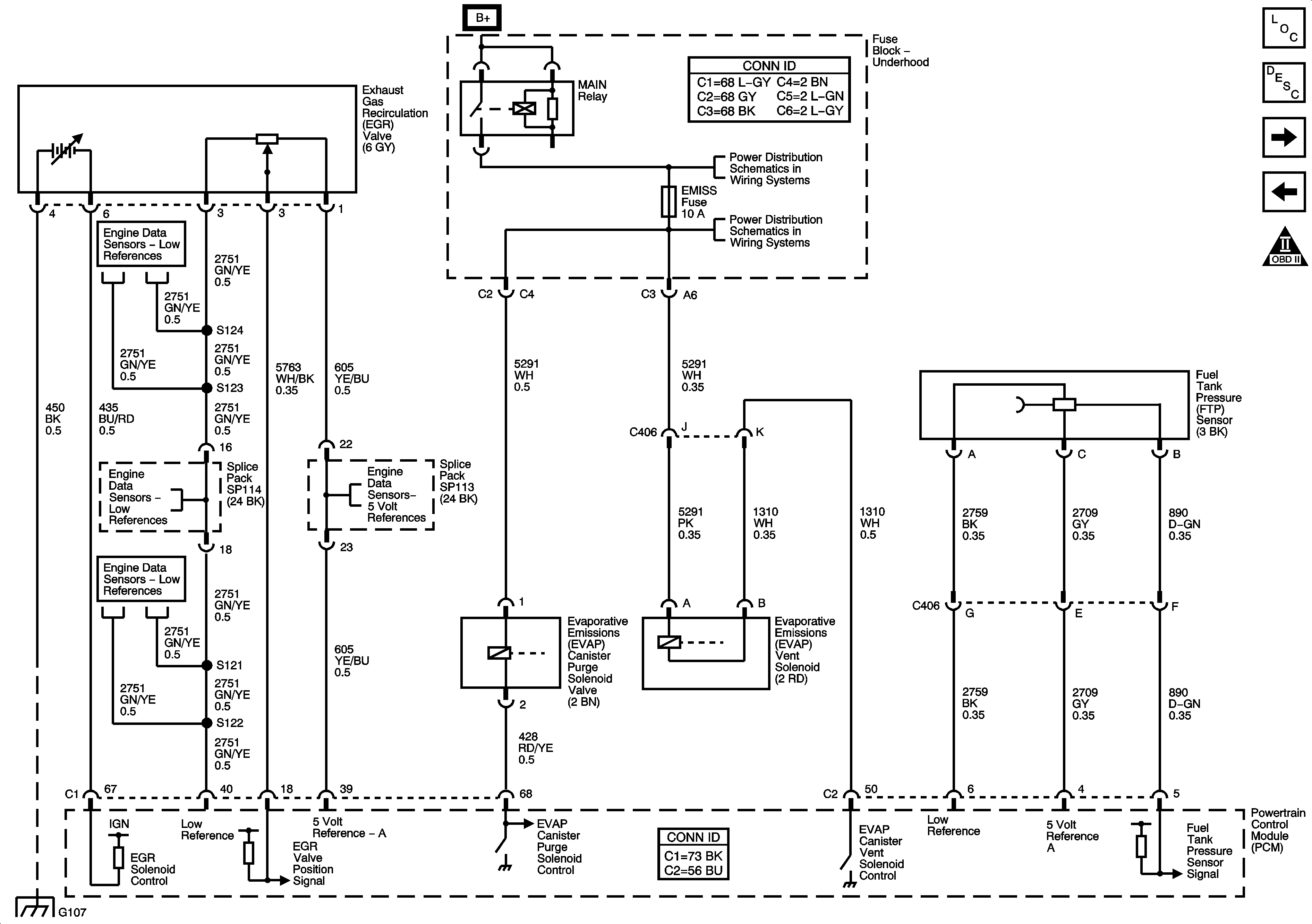
Figure 11:

EVAP Controls, EGR Valve, and FTP Sensor Signals

Object Number: 1241238  Size: FS
Master Electrical Component List
Fuel System Description
Controlled/Monitored Subsystem References
Fuel Injectors, Fuel Pump, and Valve Timing Signals
OBD II Symbol Description Notice
IGN Fuse, Ignition Switch, and the Igntion Switch Position Circuits
L66 1 of 2 - ENG MAIN Relay, EMISS Fuse, and the INJECTORS Fuse
Engine Data Sensors - Low References
Engine Data Sensors - 5 Volt References
w/L66 - G103, G105, G107, G109, and G207
Engine Data Sensors - 5 Volt References
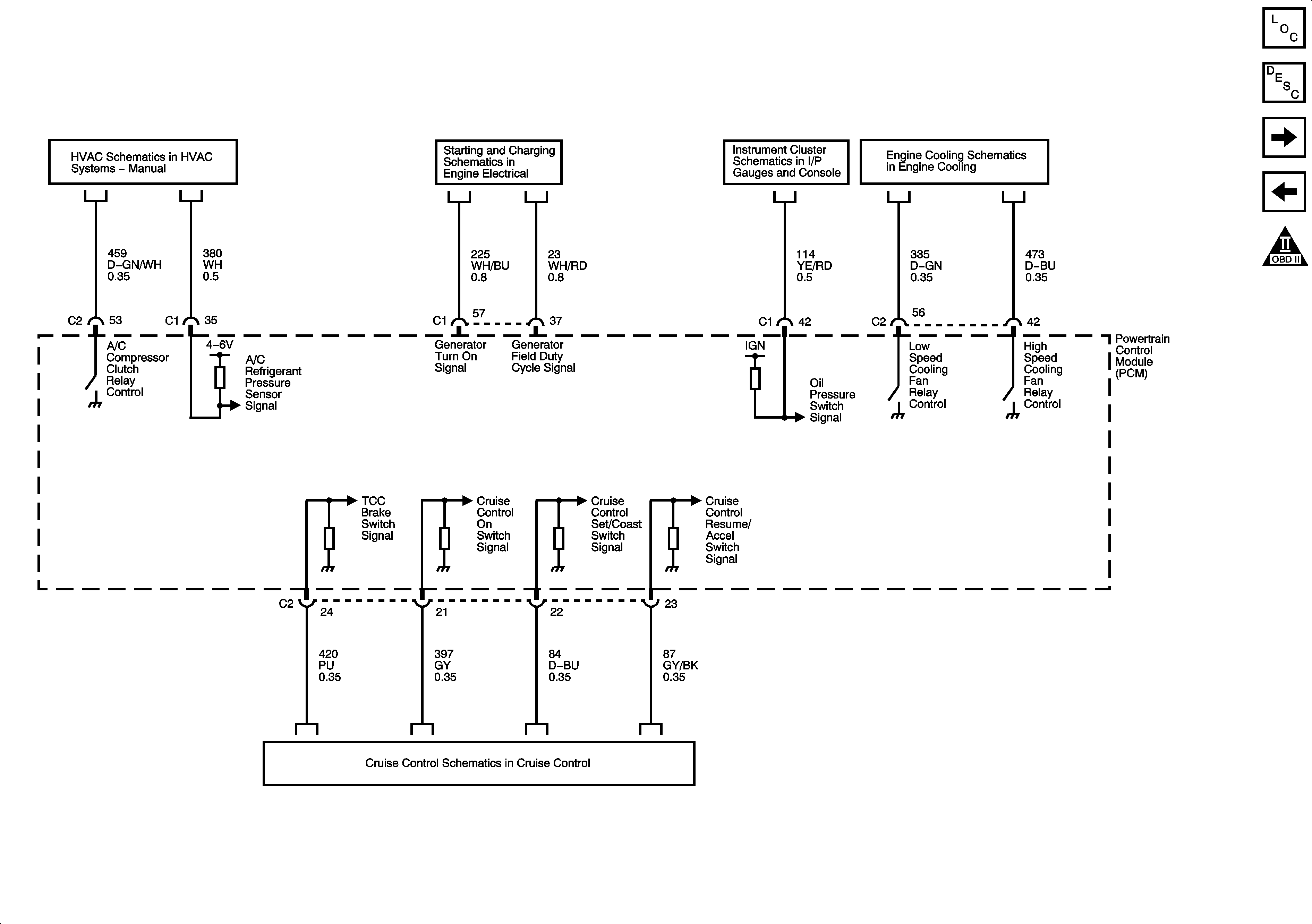
Figure 12:

Controlled/Monitored Subsystem References


Object Number: 1241242  Size: FS
Master Electrical Component List
Powertrain Control Module Description
Transmission Controls References
EVAP Controls, EGR and FTP Sensors
OBD II Symbol Description Notice
Compressor and Pressure Sensor Signals
Charging and Indicators
Indicators and MIL
Engine Cooling Schematic (L66)
Cruise Control Schematic
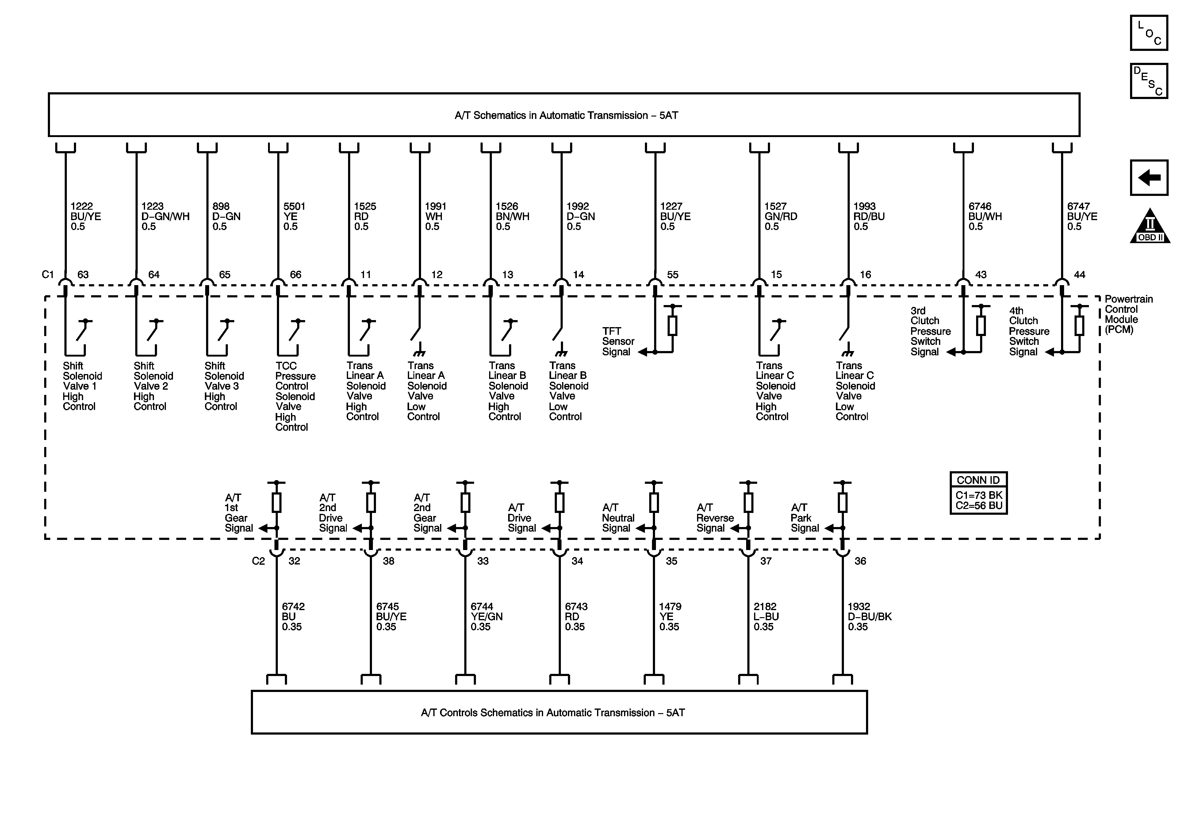
Figure 13:

Transmission Controls References


Object Number: 1241247  Size: FS
Master Electrical Component List
Powertrain Control Module Description
Controlled/Monitored Subsystem References
OBD II Symbol Description Notice
Solenoids, Switches, and Sensors
Power, Ground, PNP Switch, and Communication Data