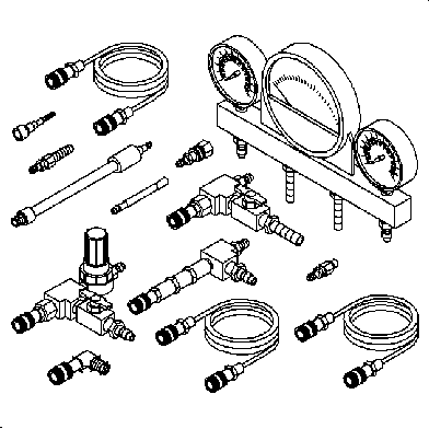
Tools Required
| • | SA9127E Gage Bar Set |
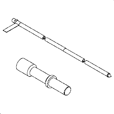
| • | SA9804E Fuel Tank Drain Hose |
Using The Fuel Pump
Caution: Do not allow smoking or the use of open flames in the area where work on the fuel or EVAP system is taking place. Anytime work is being done on the fuel system, disconnect the negative battery cable, except for those tests where battery voltage is required.
Caution: Never drain or store fuel in an open container due to the possibility of fire or explosion.
Using the fuel pump to drain the tank is the easiest procedure if the pump is operable. The fuel can be pumped out with the vehicle on the ground or on the hoist.
On The Ground
- Relieve the fuel system pressure. Refer to Fuel Pressure Relief .
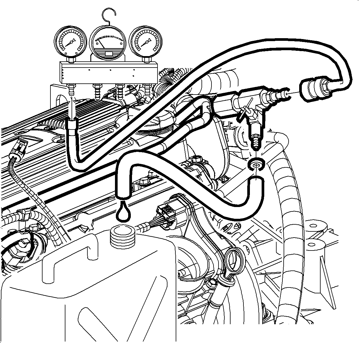
- Disconnect the fuel feed line at the fuel rail and install the 3/8 inch x 1/4 inch quick connect from the SA9127E into the fuel feed line.
- Connect a suitable drain hose to the other end of the adapter and connect the drain hose into a certified fuel handling cart.
- Connect the scan tool to the vehicle and turn the ignition ON.
- Energize the fuel pump using the scan tool. Refer to Fuel System Diagnosis .
- Pump out the fuel until no more than 1/4 tank remains.
Caution: Fuel supply lines will remain pressurized for long periods of time after the engine is shutdown. This pressure must be relieved before servicing the fuel system.
Caution: Whenever fuel line fittings are loosened or removed, wrap a shop cloth around the fitting and have an approved container available to collect any fuel.
On The Hoist
- Connect the scan tool to the vehicle diagnostic connector and turn the ignition ON.
- Relieve the fuel system pressure. Refer to Fuel Pressure Relief .
- Raise the vehicle on a hoist to a comfortable working height, keeping the scan tool outside of the vehicle and accessible from under the car.
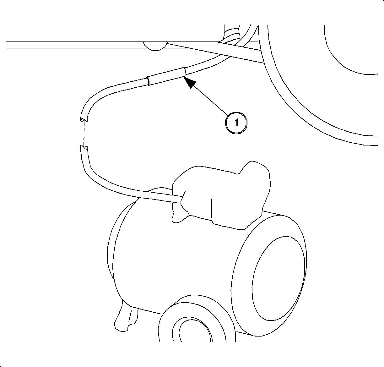
- Disconnect the chassis fuel feed line at fuel tank.
- Install the 3/8 inch x 1/4 inch quick connect (1) adapter from the SA9127E onto the fuel feed line.
- Connect a suitable drain hose to the other end of the adapter, and connect the drain hose to a certified fuel handling cart.
- Energize the fuel pump using the scan tool. Refer to Fuel System Diagnosis .
- Pump out the fuel until no more than 1/4 tank remains.
Caution: Fuel supply lines will remain pressurized for long periods of time after the engine is shutdown. This pressure must be relieved before servicing the fuel system.
Caution: Ensure that the vehicle is properly supported and squarely positioned. To help avoid personal injury when a vehicle is on a hoist, provide additional support for the vehicle on the opposite end from which the components are being removed.
Caution: Whenever fuel line fittings are loosened or removed, wrap a shop cloth around the fitting and have an approved container available to collect any fuel.
Siphoning The Fuel Tank
Caution: Do not allow smoking or the use of open flames in the area where work on the fuel or EVAP system is taking place. Anytime work is being done on the fuel system, disconnect the negative battery cable, except for those tests where battery voltage is required.
If the fuel pump is inoperative, the tank can be drained by siphoning from the tank. A suitable means is through the fuel filler pipe with the correct type and stiffness of tubing as used with the SA9804E .
- Disconnect the negative battery cable. Refer to Battery Negative Cable Disconnection and Connection in Engine Electrical.
- Open the fuel filler door and remove the gas cap.
- Insert the siphon hose guide/funnel into the fuel filler pipe.
- Insert the SA9804E into the guide funnel and into the fuel filler pipe. Some resistance may be encountered when the tip of the siphon hose reaches the inlet check valve. Repeated probing may be necessary to slide the hose tip through the check valve cage.
- Begin the fuel siphoning process. Place the fuel into an approved fuel container.
- Remove the siphon hose from the fuel filler pipe after draining is complete.
Caution: Do not allow smoking or the use of open flames in the area where work on the fuel or EVAP system is taking place. Anytime work is being done on the fuel system, disconnect the negative battery cable, except for those tests where battery voltage is required.
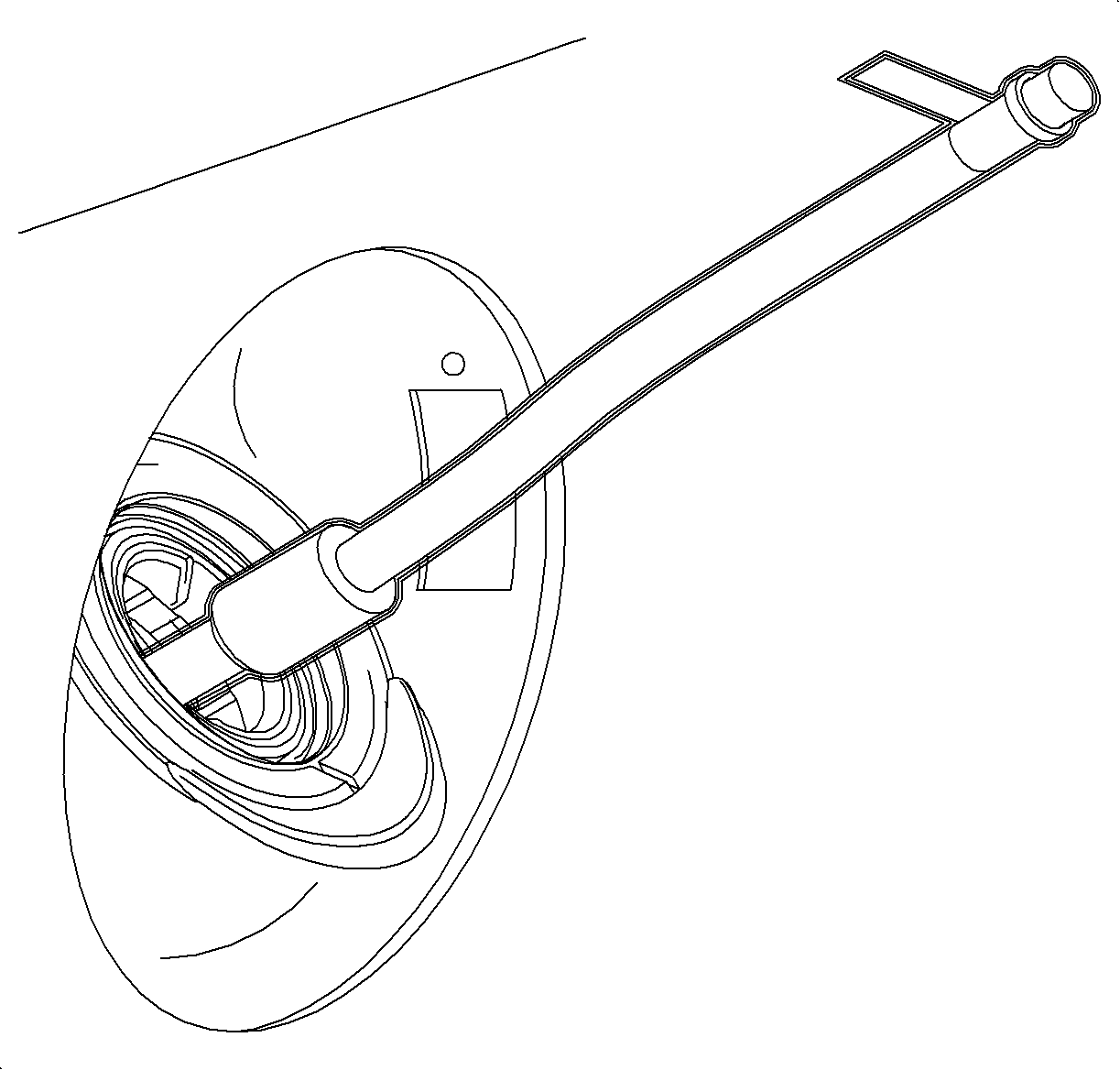
Notice: Do not attempt to insert any other type of siphon hose or tube into the fuel filler pipe. The design of the inlet check valve at the end of the fuel filler tube restricts the insertion of a hose and, most importantly, prevents the removal of this hose. See Fuel Inlet Check Valve in this section. If the siphon hose becomes stuck in the check valve, the fuel filler pipe will not be able to be removed from the fuel tank without damage to the fill pipe or fuel tank.
Important: When inserting the drain hose, take care to prevent damaging the fuel level sensor assembly.
Important: The siphon hose will reach the bottom of the tank, on the primary side only, within about 25.4 cm (10 in) of the end fitting and tag. When connecting the siphon hose to another length of hose connected to the fuel drain tanker, DO NOT insert the siphon hose into the fill pipe funnel past the tag at the fitting end. If inserted too far, the upper portion of the siphon hose may pass through the check valve cage and then jam on attempted removal.
Caution: Whenever fuel lines are removed, catch fuel in an approved container. Container opening must be a minimum of 300 mm (12 in) diameter to adequately catch the fluid.
Important: The fuel flow rate from the siphon hose will range from 1.1 L/min (0.3 gal/min) up to 3.8 L/min (1 gal/min), depending on whether it is gravity siphoned or with an air-powered pump.
