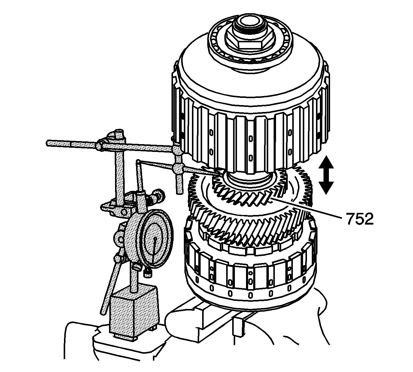
- Measure the axial clearance for the 1st drive gear (726). Measuring the axial clearance before disassembly of the 1st/2nd
clutch shaft will help determine the wear on the components and what selective washer to use during assembly.
| 1.1. | Position the 1st/2nd clutch shaft assembly in a soft-jaw vise with the nut end up. |
| 1.2. | Install the
SA9179NE
and a hole attachment tool on the 1st/coast hub (752). |
| 1.3. | Set the dial indicator to zero. |
| 1.4. | Lift up on the 1st/coast hub (752) and record the axial clearance reading. |
| 1.5. | Measure the axial clearance in 2 more locations. |
| 1.6. | Average the readings to get the axial clearance. |
Specification
1st gear axial clearance 0.085-0.130 mm (0.003-0.050 in)
| • | If the axial clearance is higher than the specification, during inspection look for excessive wear on the thrust bearing surfaces of the gears. |
| • | If there is not excessive wear, replace the 1st/coast hub washer (722) with a thicker washer to be within the axial clearance specifications. |
| • | If the axial clearance is lower than the specification, during inspection look for burrs or contamination on the thrust bearing surfaces of the gears. |
| 1.7. | Record the measurement for reference during assembly. |
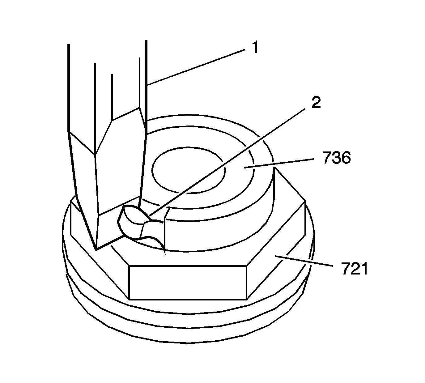
Notice: Ensure that all the metal particles are collected in order to prevent internal damage to the transmission or bearings.
- Using a chisel (1) remove the stake area from the 1st/2nd clutch shaft retaining nut (721). Do not damage the threads on the clutch shaft.
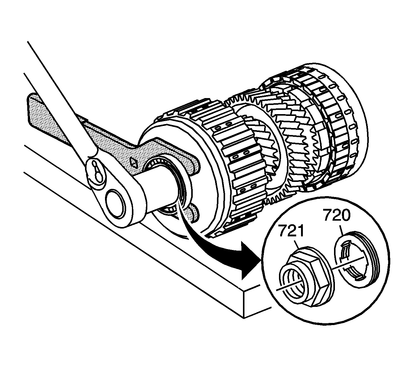
- Remove the 1st/2nd clutch shaft retainer nut (721).
| 3.1. | Lay the 1st/2nd clutch shaft assembly on a bench. |
| 3.2. | Insert
DT 46540
between the 1st/coast housing (718) and the 1st/2nd clutch shaft rear bearing (719). |
| 3.3. | Using a breaker bar and a 38 mm six-point socket loosen the 1st/2nd clutch shaft retainer nut (721). |
| 3.4. | Hold the
DT 46540
against the bench top. |
| 3.5. | Remove the 1st/2nd clutch shaft retainer nut (721). |
| 3.6. | Remove any burrs or metal shavings from the clutch shaft threads. |
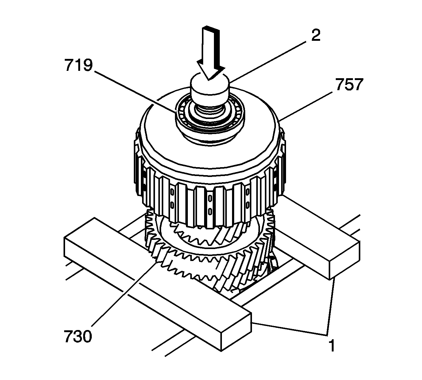
Notice: Support the component while using the press. Failure to support the
component may allow the component to drop, causing damage.
- Using a hydraulic press remove the 1st/2nd clutch shaft rear bearing (719) and the 1st/2nd clutch drive gear (730).
| • | Use press plates (1) under the 1st/2nd clutch shaft drive gear (730). |
| • | Protect the threads of the clutch shaft using a shaft protector (2). |
| • | Hold onto the 1st/2nd clutch shaft assembly to prevent the assembly from dropping. |
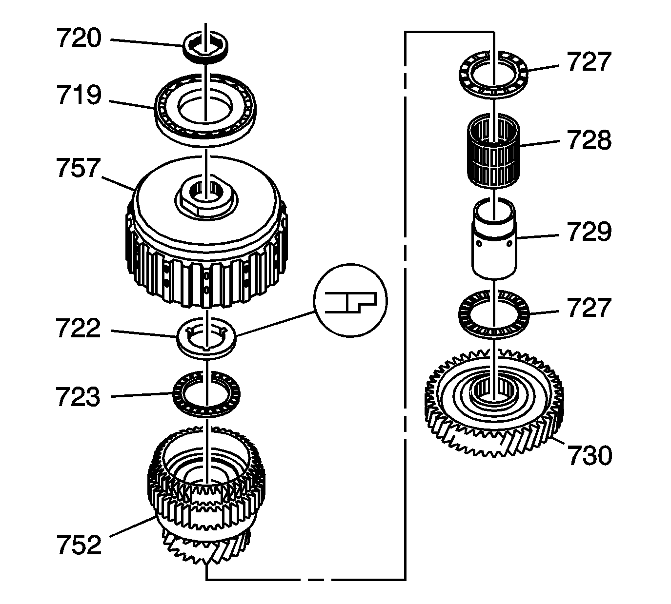
- Separate the following components,
which were removed when pressing off the rear bearing and drive gear.
| • | 1st/2nd clutch shaft retaining nut washer (720) |
| • | 1st/2nd clutch shaft rear bearing (719) |
| • | 1st/coast clutch assembly (757) |
| • | 1st/coast clutch hub thrust bearing race (722) |
| • | 1st/coast clutch hub thrust bearing (723) |
| • | 1st/coast clutch hub and coast sprag assembly (752) |
| • | 1st drive gear thrust bearing (727) |
| • | 1st drive gear inner bearing (728) |
| • | 1st drive gear inner bearing race (729) |
| • | 1st drive gear thrust bearing (727) |
| • | 1st/2nd clutch shaft drive gear (730) |
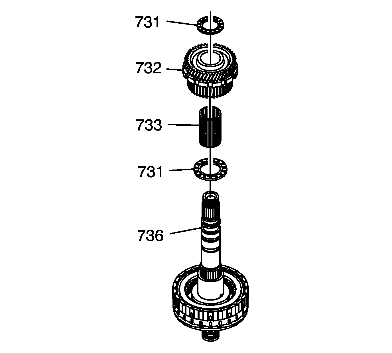
- Remove the following from the 1st/2nd clutch shaft (736):
| • | 2nd drive gear thrust bearing (731) |
| • | 2nd drive with clutch hub and park gear (732) |
| • | 2nd drive gear inner bearing (733) |
| • | 2nd drive gear thrust bearing (731) |
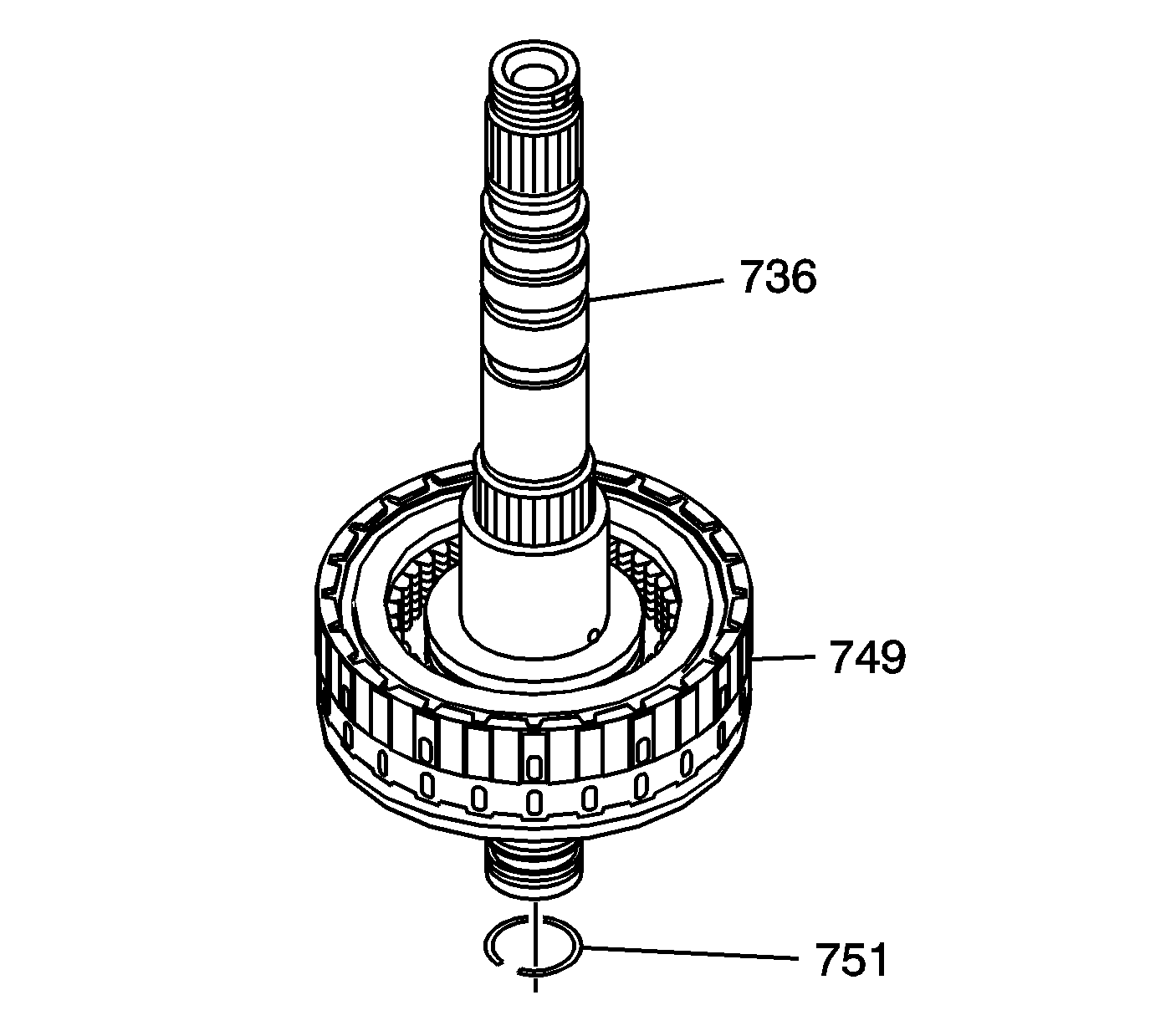
- Remove the 2nd clutch housing retaining ring (751) from the 1st/2nd clutch shaft 736).
- Remove the 2nd clutch housing assembly (749) from the 1st/2nd clutch shaft (736).
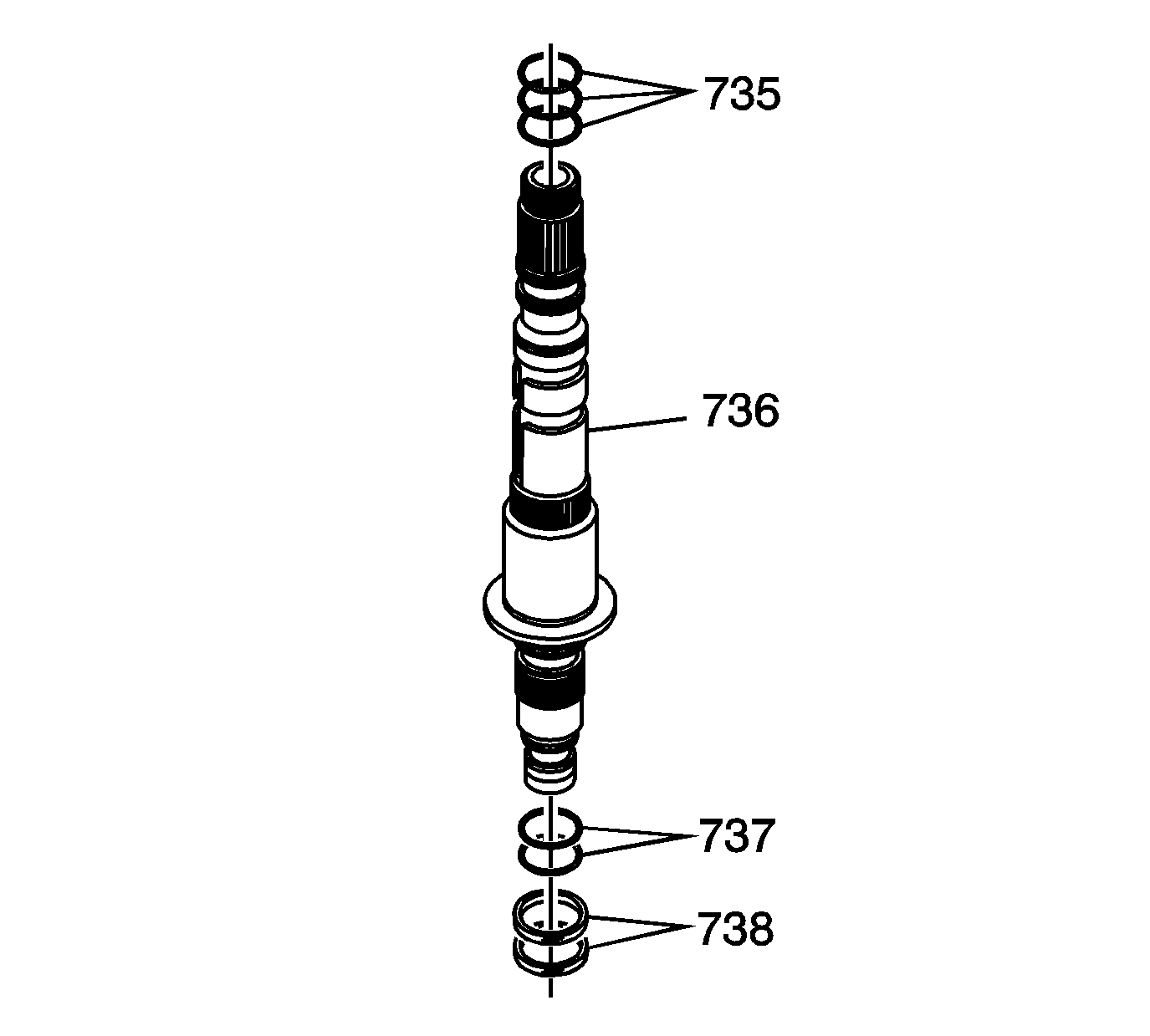
- Remove the 1st/coast clutch housing fluid passage seals (735).
- Remove the 1st/2nd clutch shaft fluid passage seals (738).
- Remove the 2nd clutch housing fluid passage seals (737).
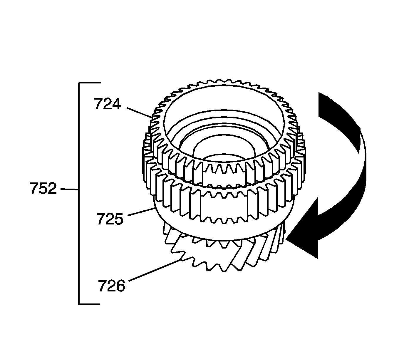
- Inspect the operation of the 1st/coast hub and coast sprag assembly (752).
| • | Hold the coast clutch hub (724) and turn clockwise the 1st drive gear (726). The assembly should turn freely clockwise. |
| • | Turn the 1st drive gear (726) the opposite direction, counterclockwise. The assembly should lock. |
- Inspect the gears on the 1st/coast hub and coast sprag assembly (752) for damage or excessive wear.
- Replace the 1st/coast hub and coast sprag assembly (752) if faulty. The one-way clutch and the hub are serviced as an assembly.
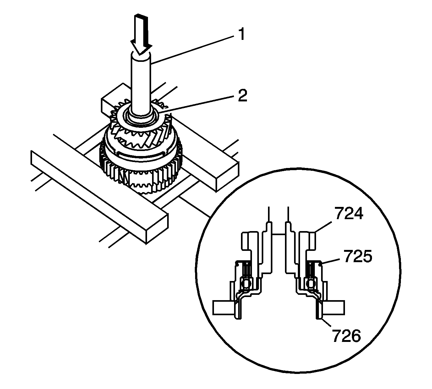
Important: If necessary the 1st/coast hub and coast sprag assembly (752) can be disassembled for cleaning.
- Using
EN 46342
(1) and
DT 46516
(2) with a hydraulic press, remove the coast clutch hub (724) form the 1st drive gear (726).
- Clean the components in solvent and air dry.
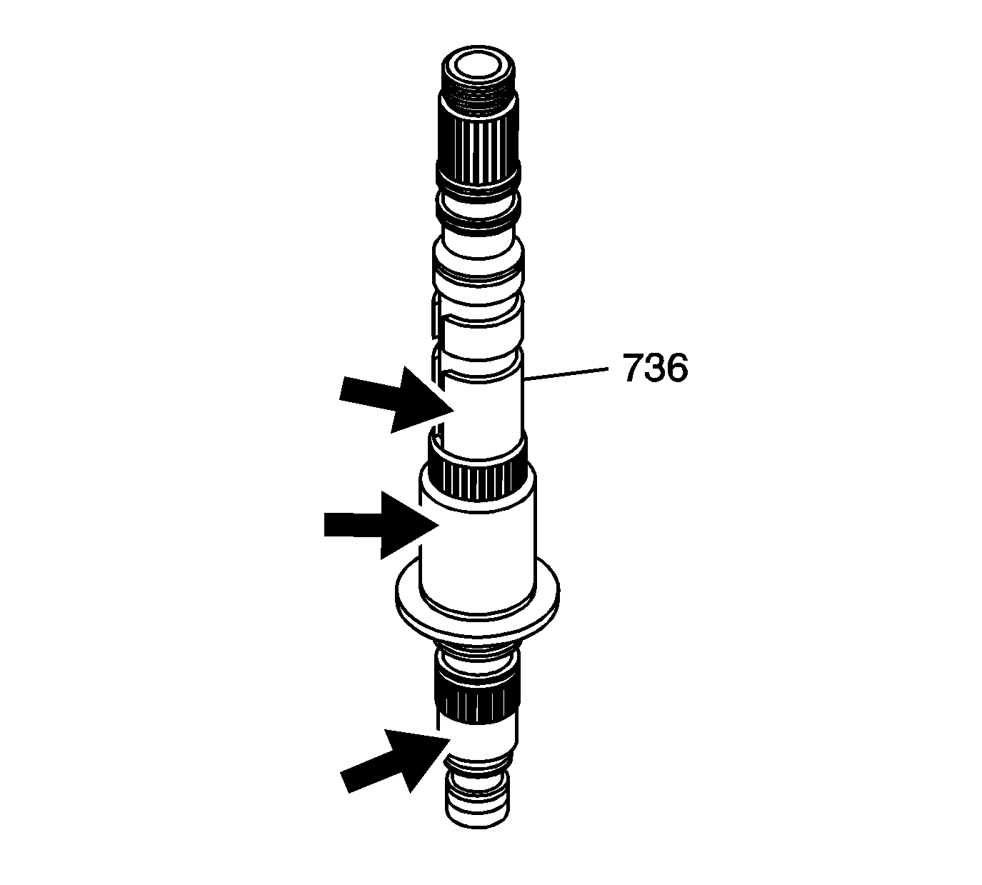
- Clean the 1st/2nd clutch shaft (736) in solvent, air dray and blow out the oil passages.
- Inspect the 1st/2nd clutch shaft (736) for the following conditions:
Refer to 1st/2nd Clutch Shaft in
Transmission Clearance Specifications
.
| • | Shaft splines for excessive wear, witness marks from the gears is normal |
| • | Bearing journal surfaces for wear, scoring, or brinelling |
| • | Fluid passage seal grooves for damage |
| • | Thrust bearing surface on shaft flange for excessive wear, roughness, or scoring |
- Replace the 1st/2nd clutch shaft (736) if faulty.
- Clean the gears and bearing for the 1st/2nd clutch shaft insolvent and air dry.
- Inspect the gears for damaged teeth.
- Inspect the thrust surface on the gears for excessive wear and scoring.
- Inspect the bearings for roughness, brinneling, or bent cages.
- Replace any faulty components.


