For 1990-2009 cars only
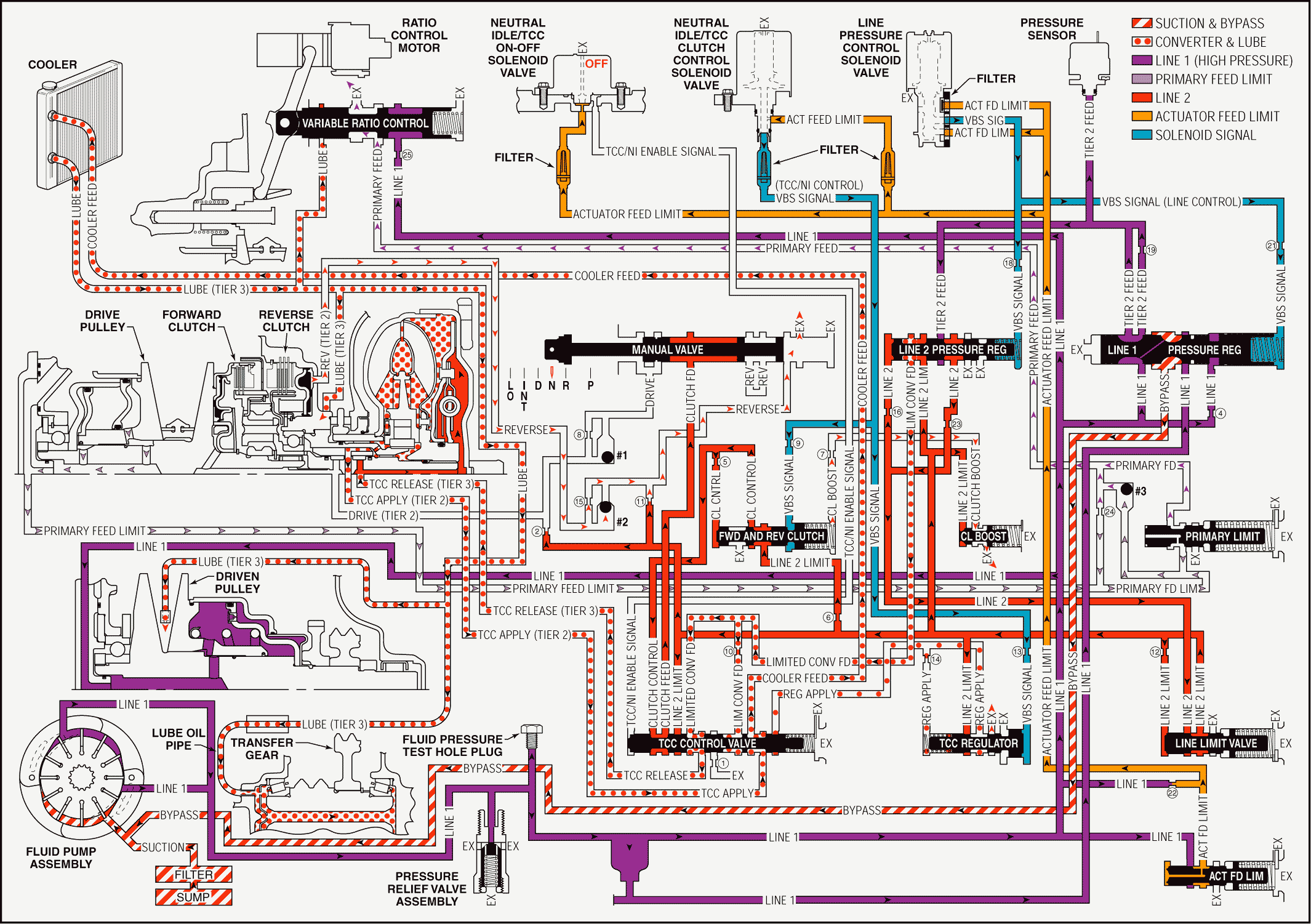
When the range selector lever is moved to the Neutral (N) position, the hydraulic and electrical system operation is identical to Park (P) range. However, if Neutral is selected after the vehicle was operating in Reverse (R), the following changes would occur in the hydraulic system:
Reverse Clutch Releases
Important: Remember that the function of an orifice is to control the flow rate of fluid and the rate of apply or release of a clutch.
Manual Valve: The manual valve is moved to the Neutral position and blocks clutch feed pressure from entering the reverse fluid circuit. The reverse fluid circuit is opened to an exhaust at the manual valve.Reverse Clutch: Reverse clutch fluid exhausts from the reverse clutch to the #2 ball check valve allowing the reverse clutch to release.
#2 Ball Check Valve: Exhausting reverse clutch fluid seats the #2 ball check valve and is forced to pass through orifice #15. Reverse fluid then flows to the manual valve where it exhausts.
Pressure Regulation
Line Pressure Control Solenoid Valve: The line pressure control solenoid valve duty cycle is ramped down, decreasing VBS signal (line control) fluid pressure.Line 2 Pressure Regulator Valve: When VBS signal fluid pressure decreases, orificed line 2 fluid pressure is able to move the line 2 pressure regulator valve against spring force, thus decreasing the amount of tier 2 feed fluid pressure that is regulated into the line 2 circuit.
Line Limit Valve: Because line 2 fluid pressure is decreased, the amount of fluid regulated through the line limit valve into the line 2 limit fluid circuit is also decreased.
Clutch Boost Valve: When line 2 limit fluid pressure is decreased, the clutch boost valve spring is able to shift the clutch boost valve to the released position, allowing clutch boost fluid to exhaust.
Forward and Reverse Clutch Valve: When clutch boost fluid exhausts, VBS signal and orificed clutch control fluid pressures are able to move the forward and reverse clutch valve against spring force. This decreases the amount of 2 limit fluid pressure regulated into the clutch control circuit.
TCC Control Valve: Decreased clutch control fluid pressure passes through the TCC control valve, thus decreasing the pressure in the clutch feed circuit. Extra fluid pressure is not required at the manual valve in Neutral because no clutches are applied.
Ratio Control
Important: Allowing fluid to bypass an orifice when exhausting ensures a quick release of the clutch or pulley. This prevents the friction material from dragging and creating excess fluid temperatures or damaging the clutch.
Ratio Control Motor and Variable Ratio Control Valve: The ratio control motor is commanded by the TCM to the low ratio position and moves the variable ratio control valve against spring force. This blocks line 1 fluid and allows primary feed fluid pressure to exhaust.Variable Drive Pulley Assembly Released: Primary feed limit fluid exhausts from the variable drive pulley assembly releasing the variable drive pulley piston.
#3 Ball Check Valve: Exhausting primary feed fluid unseats the #3 ball check valve, allowing a quick exhaust of fluid into the primary feed limit circuit. Primary feed limit fluid then exhausts at the variable ratio control valve.
Neutral - Engine Running

