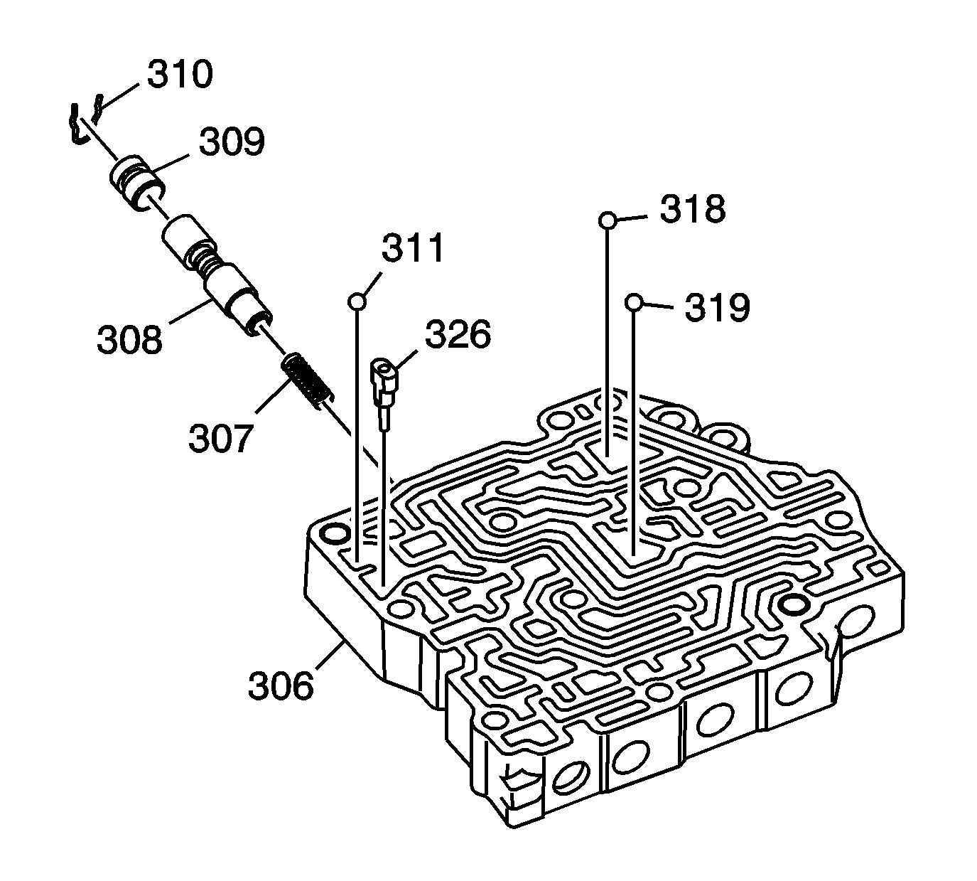
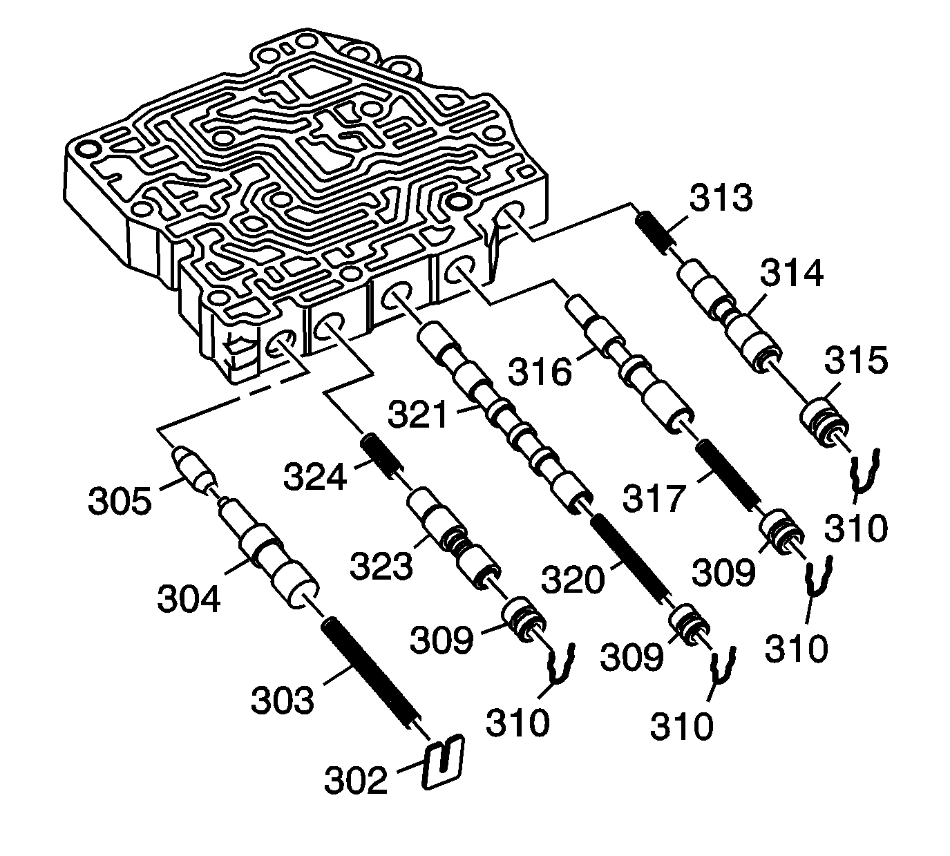
Removal Procedure

Caution: Valve springs can be tightly compressed. Use care when removing retainers
and plugs. Personal injury could result.
Notice: Do not use a magnet in order to remove the control valve body ball check
valves. This may magnetize the control valve body ball check valves, causing
metal particles to stick to them.
- Remove the following steel check balls from the servo valve body (306):
| • | 1st clutch accumulator check valve (311) |
| • | 1st clutch check valve (318) |
| • | 2nd clutch check valve (319) |
- Remove the 1st accumulator choke (326).
- Remove the valve bore plug retainer clip (310) from the servo valve
body, then remove the following components:
| • | The valve bore plug (308) |
| • | The clutch pressure control (CPC) valve (308) |
| • | The CPC valve return spring (307) |

Caution: Valve springs can be tightly compressed. Use care when removing retainers
and plugs. Personal injury could result.
- Remove the following:
| • | Valve bore plug retainer clip (310), bore plug (315), reverse
CPC valve (314), and Reverse CPC valve return spring (313). |
| • | Valve bore plug retainer clip (310), bore plug (309), return
spring (317), and servo control valve (316). |
| • | Valve bore plug retainer clip (310), bore plug (309), return
spring (320), and shift valve C (321). |
| • | Valve bore plug retainer clip (310), bore plug (309), CPC
valve A (323), and return spring (324). |
| • | Valve bore retainer (302), return spring (303), kick-down
valve (304), and kick-down short valve (305). |
Inspection Procedure
Caution: When you use compressed air in order to clear fluid passages and to
dry parts, always aim the air pressure away from face and eyes. Always wear
adequate eye protection in order to avoid injury from dirt and debris that
may adhere to parts.
- Clean all parts thoroughly and dry them with compressed air. Blow out all passages.
- Inspect the servo valve body for scoring and damage.
- Inspect all valves for wear or damage. If a valve does not operate, refer
to
General Valve Body Service Instructions
.
- Lubricate all parts with automatic transmission fluid during assembly.
Installation Procedure

- Install the reverse CPC valve (314),
return spring (313), bore plug (315), and valve bore plug retainer clip (310).
- Install the servo control valve (316), return spring (317),
bore plug (309), and valve bore plug retainer clip (310).
- Install the shift valve C (321), return spring (320),
bore plug (309), and valve bore plug retainer clip (310).
- Install the CPC valve A, return spring (324), control valve A (323),
bore plug (309), and valve bore plug retainer clip (310).
- Install the kick-down short valve (305), kick-down
valve (304), return spring (303), and valve bore retainer plate (302).

- Install the clutch pressure control valve B
return spring (307), control valve B (308), bore plug (309),
and retainer clip (310).
- Install the following steel check balls in their correct passages:
| • | 1st clutch accumulator check valve (311) |
| • | 1st clutch check valve (318) |
| • | 2nd clutch check valve (319) |
- Install the 1st accumulator choke (326).


