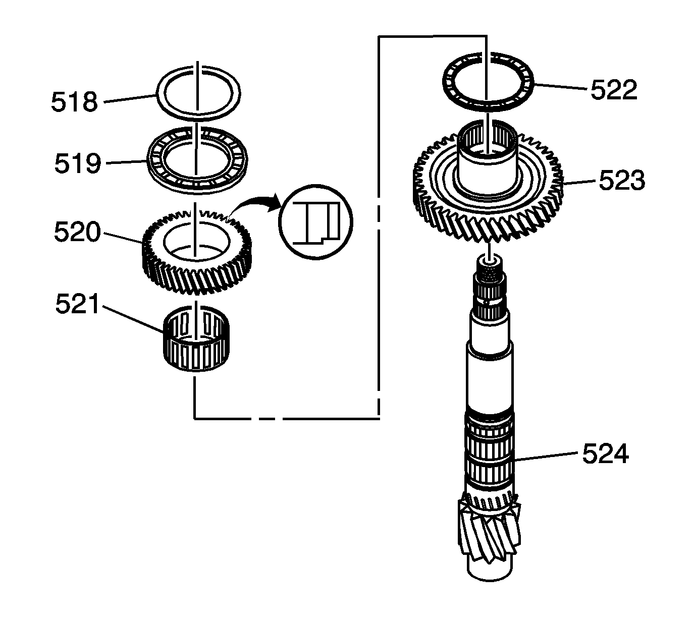
- Install the following components on the
output shaft:
| • | The 1st/2nd driven gear (523) |
| • | The 1st/2nd driven gear 65 x 83 x 4.5 mm thrust bearing (522) |
| • | The 1st/2nd idler gear 57 x 65 x 28.7 mm inner bearing (521) |
| • | The 1st/2nd idler gear (520) with shoulder side down |
| • | The 1st/2nd idler gear 56 x 878.5 x 5.5 mm thrust bearing (519) |
| • | The 1st driven gear 56 mm selective spacer (518) |
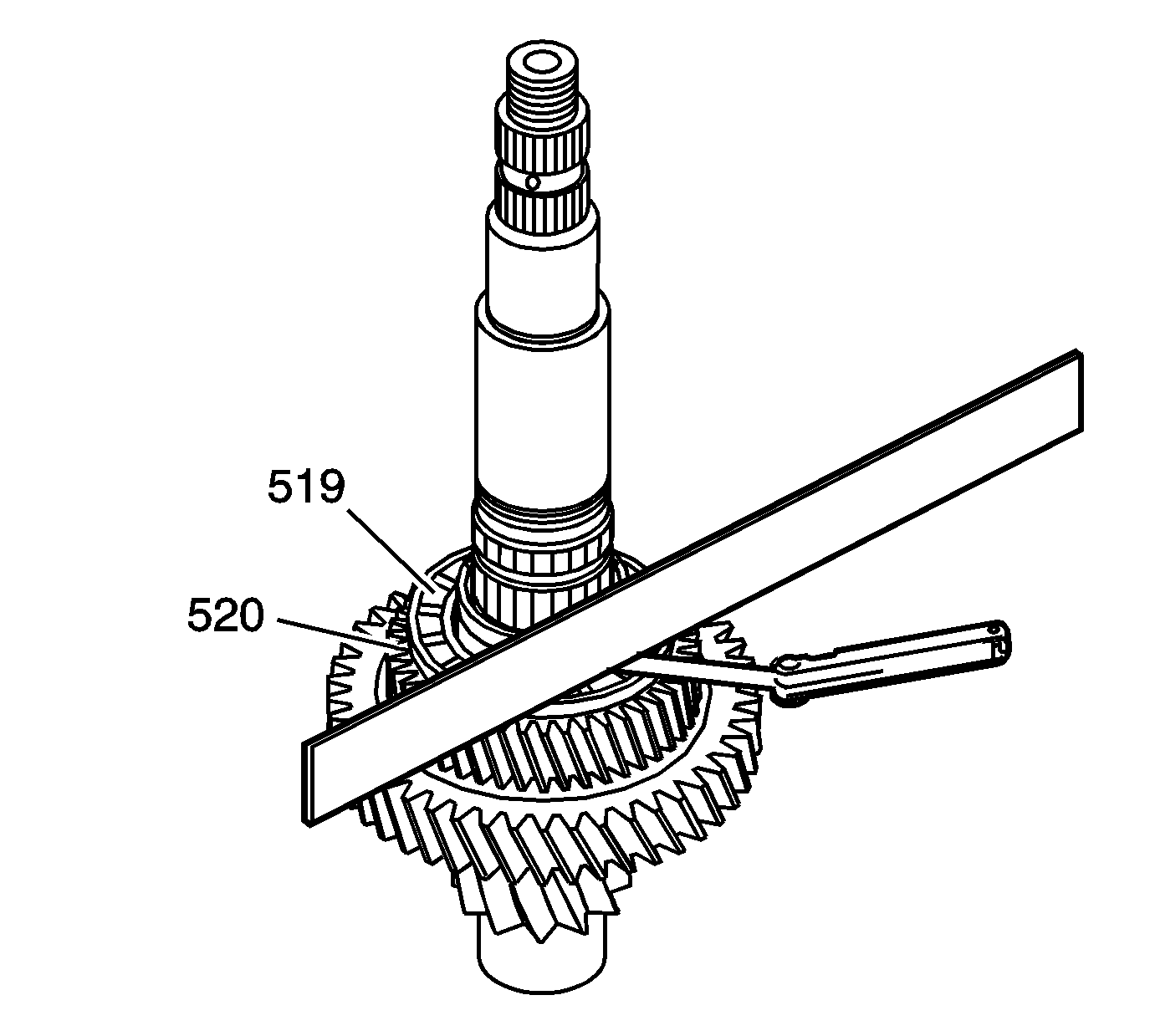
- Put a straight edge across the top of the
1st/2nd idler gear thrust bearing (519).
- Using a feeler gage measure between the straight edge and the roller bearings
on the 1st/2nd idler gear thrust bearing (519) in 3 places. Use the average
of the 3 measurements as the actual clearance.
- Measure the 1st/2nd idler gear (520) axial clearance in at least
3 places on the gear. Use the average of the 3 measurements as the actual clearance.
Specification
1st/2nd idler gear clearance 0.005-0.040 mm
(0.0002-0.0016 in)
- If the measurement exceeds the specifications, remove and measure the
thickness of the 1st driven gear 56 mm selective spacer (518).
- Select and install a new 1st driven gear 56 mm selective spacer (518)
in order to obtain the specified clearance. Measure the clearance again to ensure
that the 1st/2nd idler gear is within specifications.
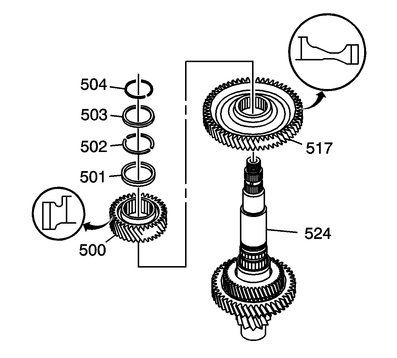
- Install the following components on the
output shaft:
| • | The 1st driven gear (517) with the gear protrusion facing up |
| • | The 3rd/4th driven gear (500) with the gear protrusion facing up |
| • | The 3rd/4th driven gear 50.2 mm selective spacer (501) |
| • | The 3rd/4th driven gear 39 mm split retaining rings (502) |
| • | The 3rd/4th driven gear 39 mm retaining ring cap (503) |
| • | The 3rd/4th driven gear 39 mm retaining ring cap retainer (504) |
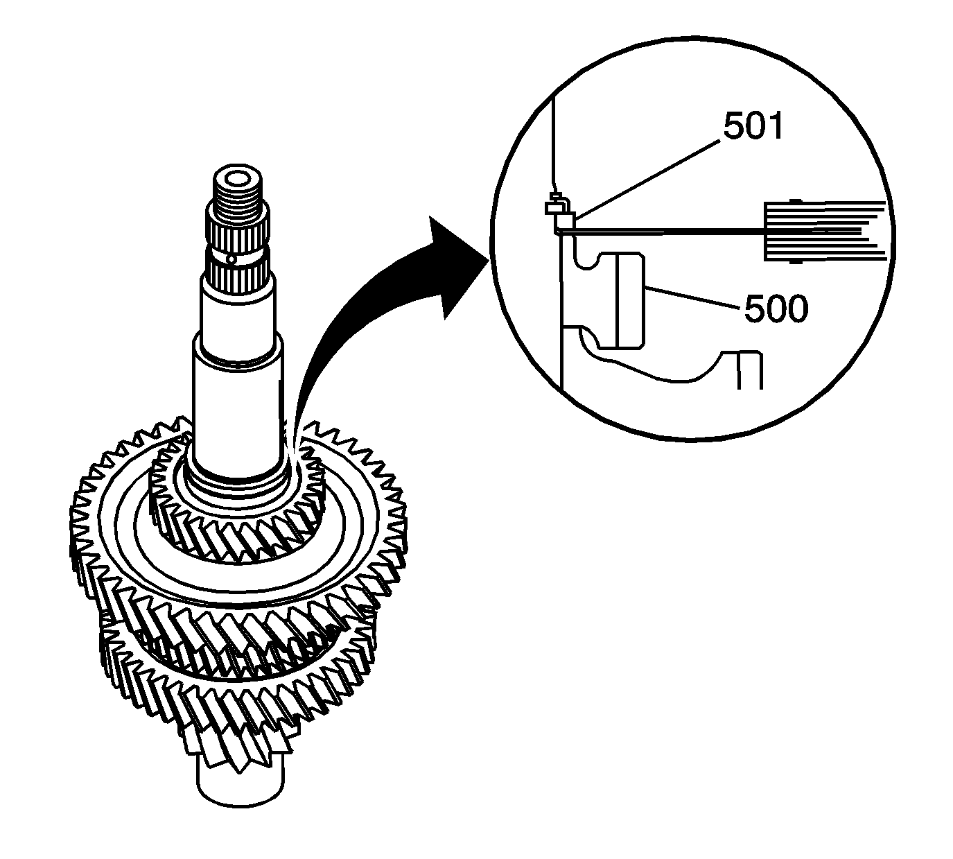
- Measure the clearance between the 3rd/4th
driven gear (500) and the 3rd/4th driven gear 50.2 mm selective spacer (501)
with a feeler gage (1) in at least 3 places. Use the average of the
3 measurements as the actual clearance.
Specification
The clearance between the 3rd/4th driven gear
and the 3rd/4th driven gear selective spacer 0.005-0.040 mm (0.0002-0.0016 in).
- If the measurement exceeds 0.040 mm (0.016 in), remove and
measure the thickness of the 3rd/4th driven gear 52 mm selective spacer (501).
- Select and install a new 3rd/4th driven gear 52 mm selective spacer (501)
in order to obtain the specified clearance, then check for the proper clearance again.
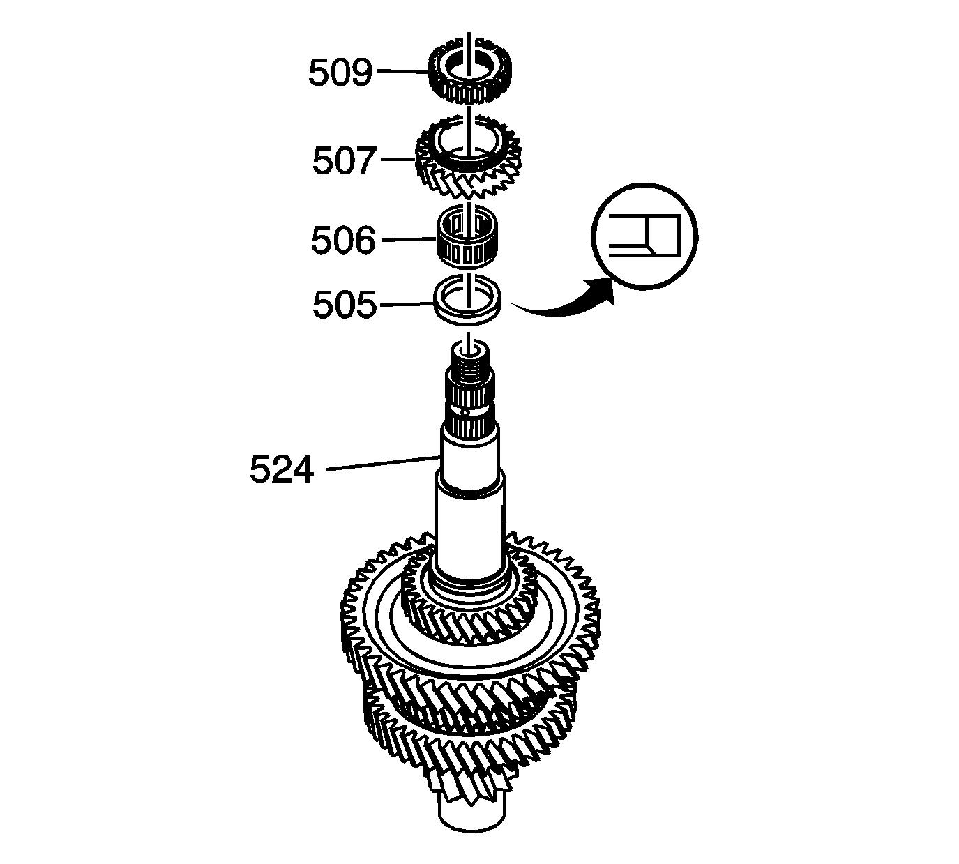
- Install the following components on the output shaft:
| • | The 5th driven gear spacer (505) |
| • | The 5th driven gear inner bearing (506) |
| • | The 5th driven gear (507) |
| • | The 5th/reverse synchronizer hub (509) |
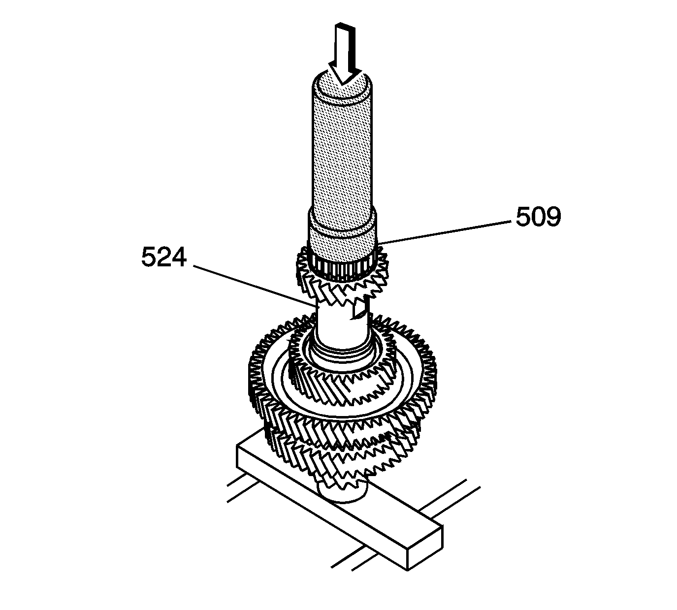
- Using a hydraulic press and
DT 46509
complete the installation of the 5th/reverse
synchronizer hub (509).
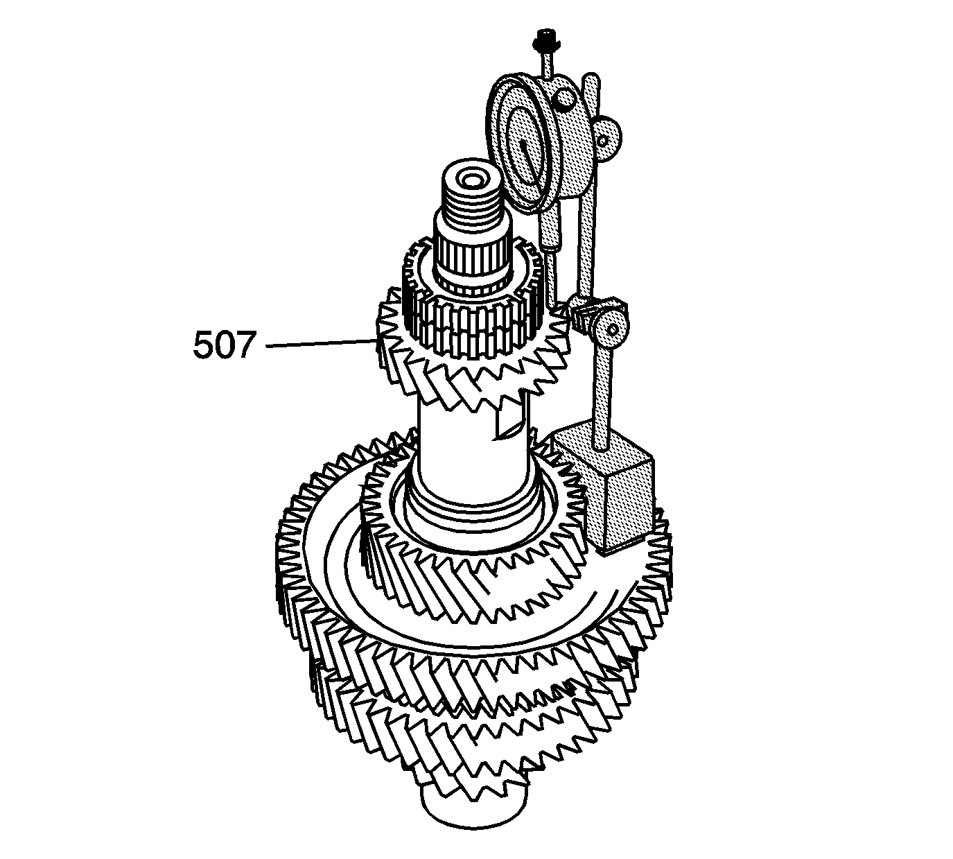
- Measure the 5th driven gear (507)
axial clearance.
| 13.1. | Install
SA9179NE
on
the 5th driven gear. |
| 13.3. | Lift up on the 5th driven gear and record the measurement. |
Specification
5th driven gear axial clearance 0.12-0.27 mm
(0.0047-0.0106 in)
| 13.4. | If the clearance exceeds specifications inspect for excessive wear on
the thrust surface of the 5th driven gear (507), the 5th/reverse synchronizer
hub (509), and the shoulder of the output shaft (524). |
| 13.5. | If there is not any clearance, ensure the 5th/reverse synchronizer hub (509)
is completely installed and there are no burrs or debris between the gears. |
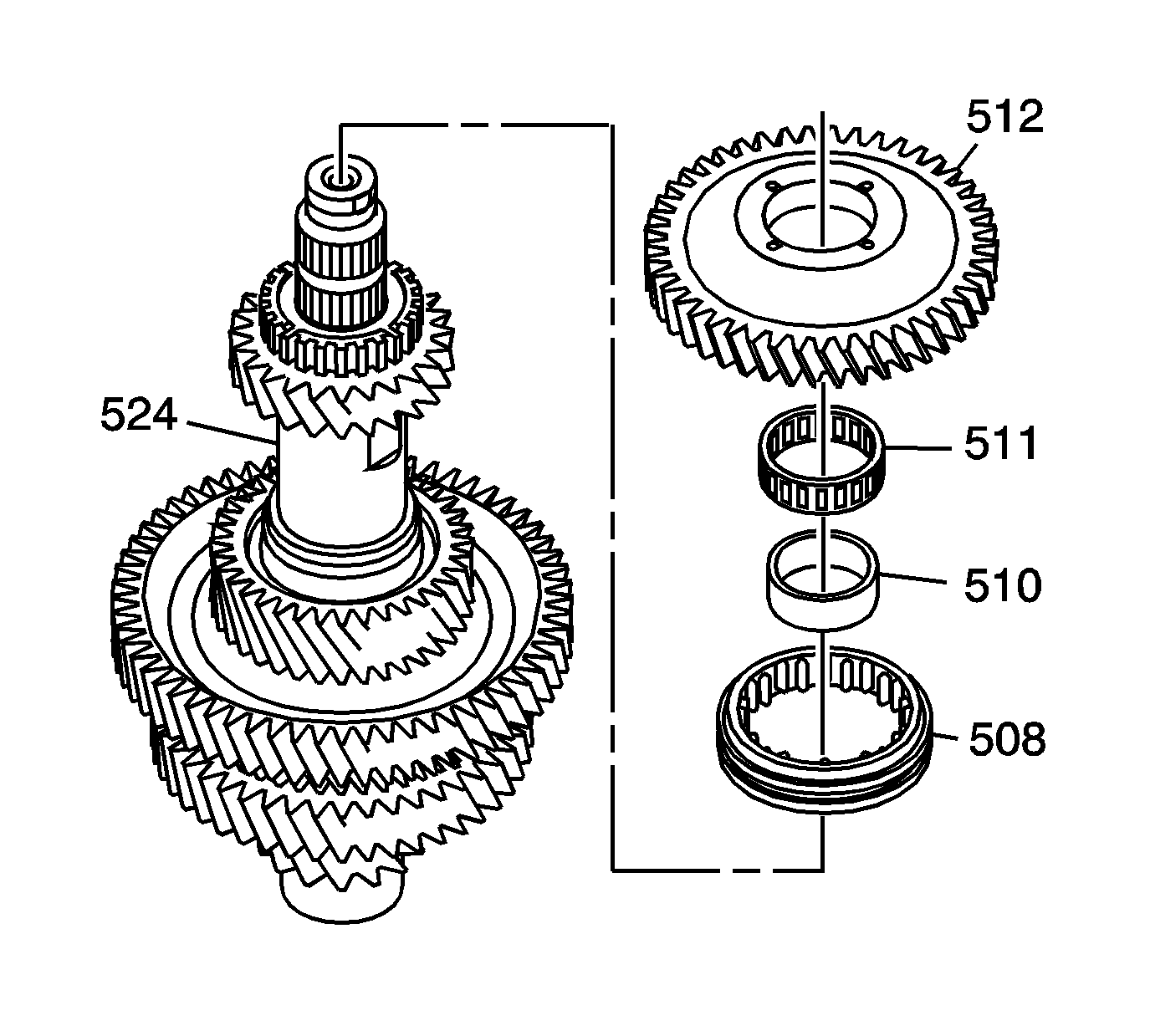
- Install the following components on the
output shaft (524):
| • | The 5th/reverse synchronizer sleeve (508) |
| • | The reverse driven gear 31 x 40 x 14.5 mm inner bearing race (510) |
| • | The reverse driven gear 40 x 46 x 14.5 mm inner bearing (511) |
| • | The reverse driven gear (512) |
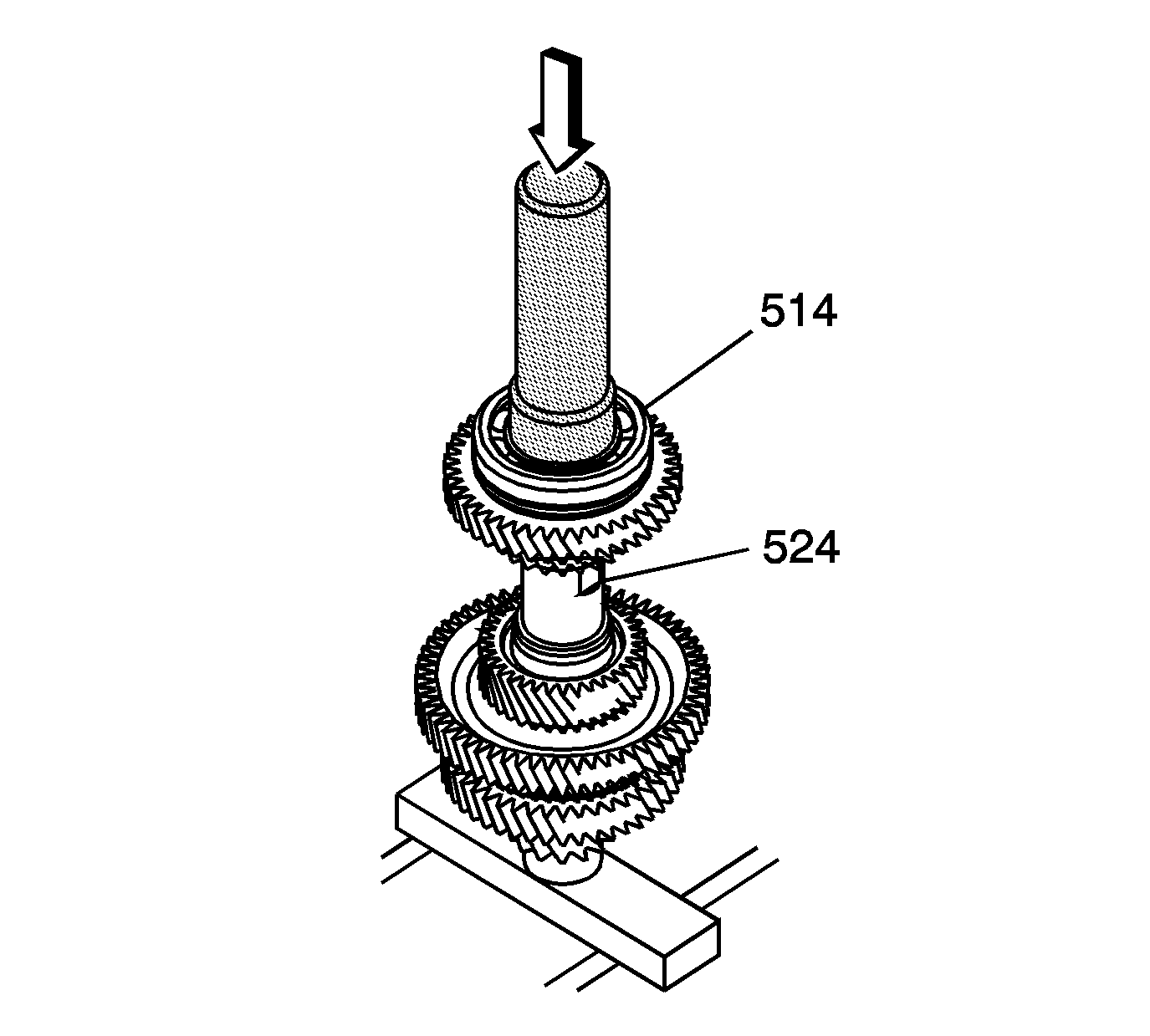
- Using the
DT 46509
and a hydraulic press, install the output shaft 31 x 93 x 19 mm
rear bearing (514) on the output shaft (524).
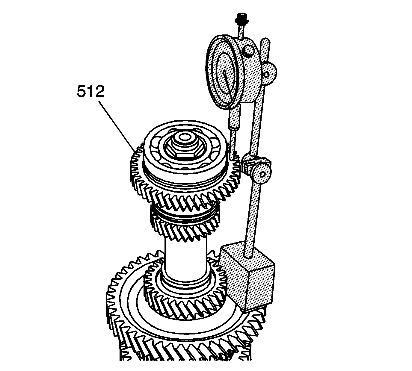
- Measure the reverse driven gear (512) axial clearance.
| 16.1. | Install
SA9179NE
on
the reverse driven gear. |
| 16.3. | Lift up on the reverse driven gear and record the measurement. |
Specification
Reverse driven gear axial clearance 0.10-0.25 mm
(0.0039-0.0098 in)
| 16.4. | If the clearance exceeds specifications inspect for excessive wear on
the thrust surface of the reverse driven gear (512) or the 5th/reverse synchronizer
hub (509). |
| 16.5. | If there is not any clearance, ensure the output shaft rear bearing (514)
is completely installed and there are no burrs or debris between the gears. |
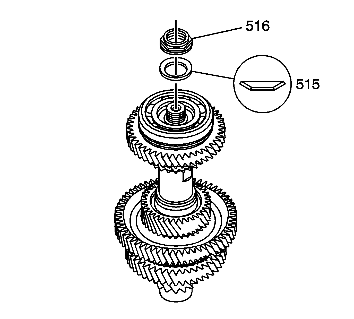
- Install an output shaft washer (515)
in the direction as shown.
- Loosely install an output shaft retaining nut (516).
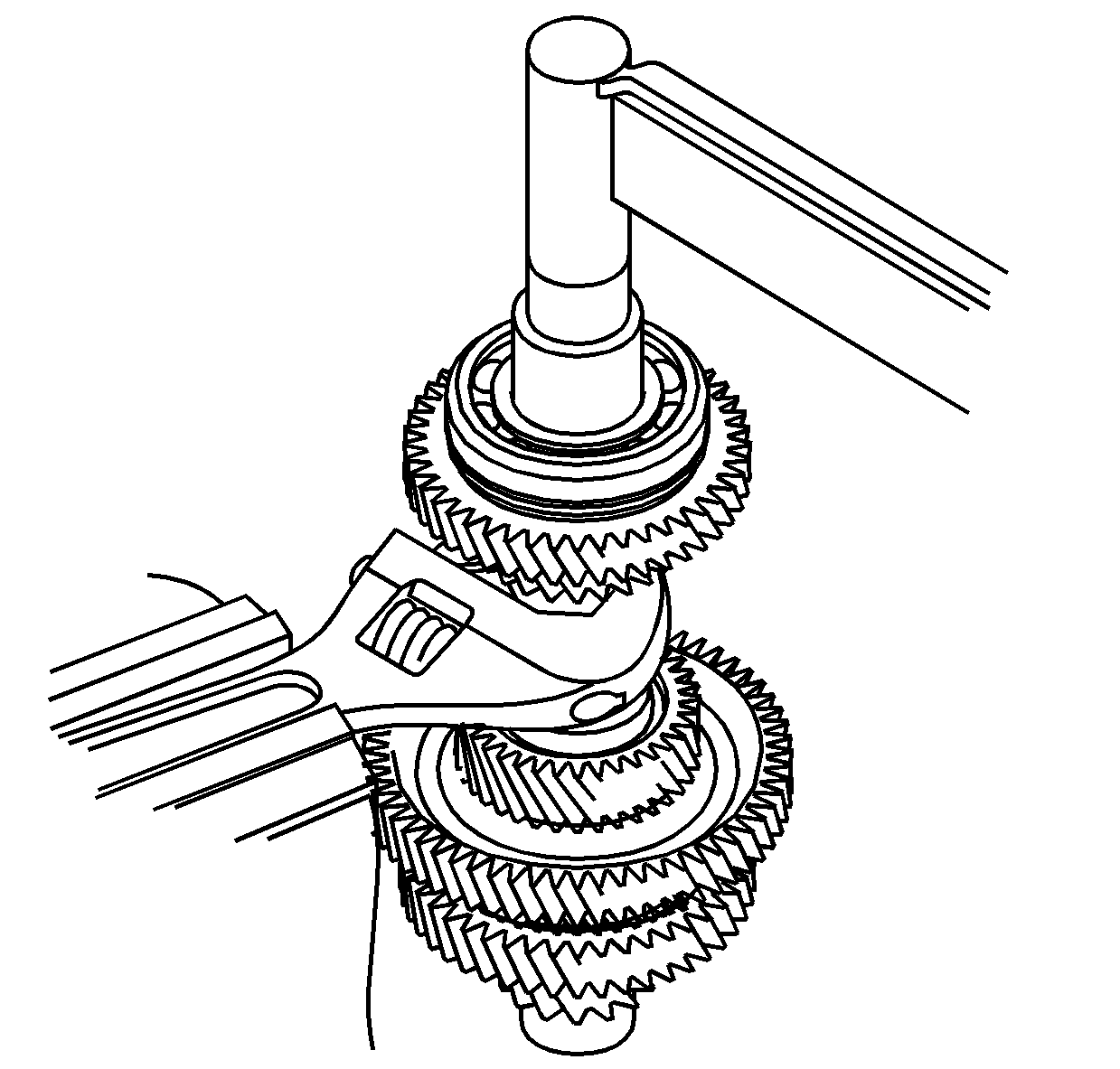
Important:
| • | Do not use an impact wrench to tighten the nut. |
| • | The nut is left handed thread. |
- To tighten the retaining nut (516), use an adjustable wrench mounted
in a vise. Securely hold the output shaft in the adjustable wrench while tightening.
Tighten
Tighten the nut to 167 N·m (123 lb ft).
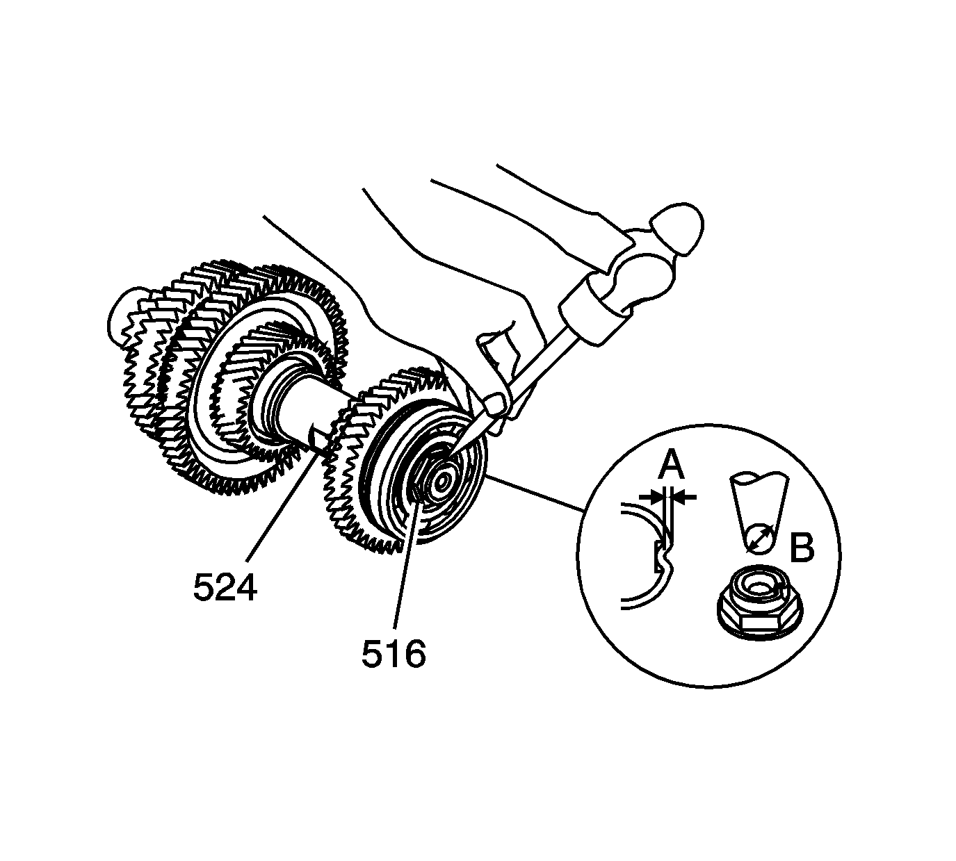
- Using a 3.5 mm (9/64 in) punch (b),
stake the output shaft nut (516) in place on the output shaft (524)
to the specified depth (a).
Specification
Stake the nut to 0.7-1.3 mm (0.03-0.05 in.)


