For 1990-2009 cars only
Tools Required
| • | J 23327 Spring Compressor |
| • | J 28585 Snap Ring Remover |
| • | J 45124 Removable Bridge |
Note these items during assembly:
| • | Clean all parts thoroughly and dry them. |
| Caution: When you use compressed air in order to clear fluid passages and to dry parts, always aim the air pressure away from face and eyes. Always wear adequate eye protection in order to avoid injury from dirt and debris that may adhere to parts. |
| • | Use compressed air to clear all passages. |
| • | Apply automatic transmission fluid to all O-ring seals before assembly. |
| • | Soak all clutch fiber plates thoroughly in automatic transmission fluid for a minimum of 30 minutes. |
- Install new O-ring seals in the 2nd clutch piston (746) as follows:
- Install the 2nd clutch piston (746) into the 2nd clutch housing (749) by applying hand pressure and rotating the 2nd clutch piston assembly.
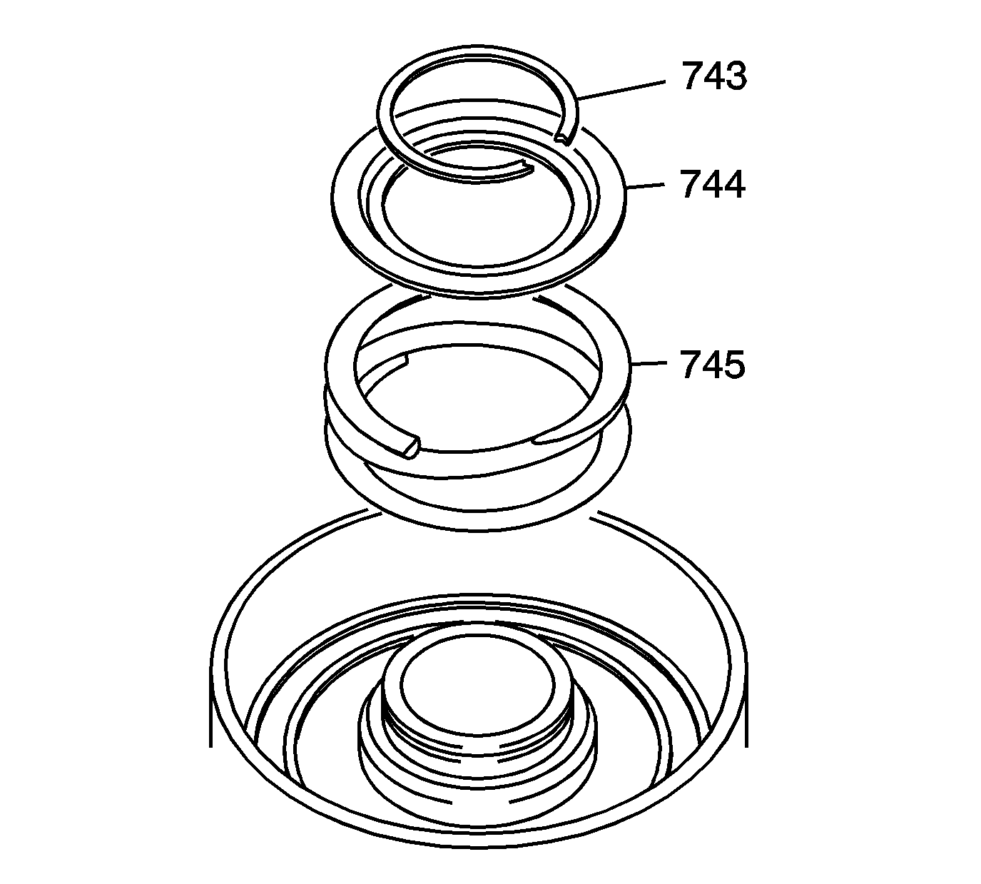
- Install the 2nd clutch piston return spring (745).
- Install the 2nd clutch piston retainer cap (744).
- Install the 2nd clutch piston 42 mm retaining ring (743) on top of the retainer cap (744).
- Using the bridge and legs of the J 45124 (2) with the forcing screw of the J 23327 (1) and J 21420-2 (3) plate of the J 23327 , compress the clutch piston return spring until the groove for the clutch spring retainer cap retaining ring (743) is accessible.
- Install the 42 mm, 2nd clutch piston retaining ring (743).
- Remove the tools.
- Install into the 2nd clutch housing (749) the following components:
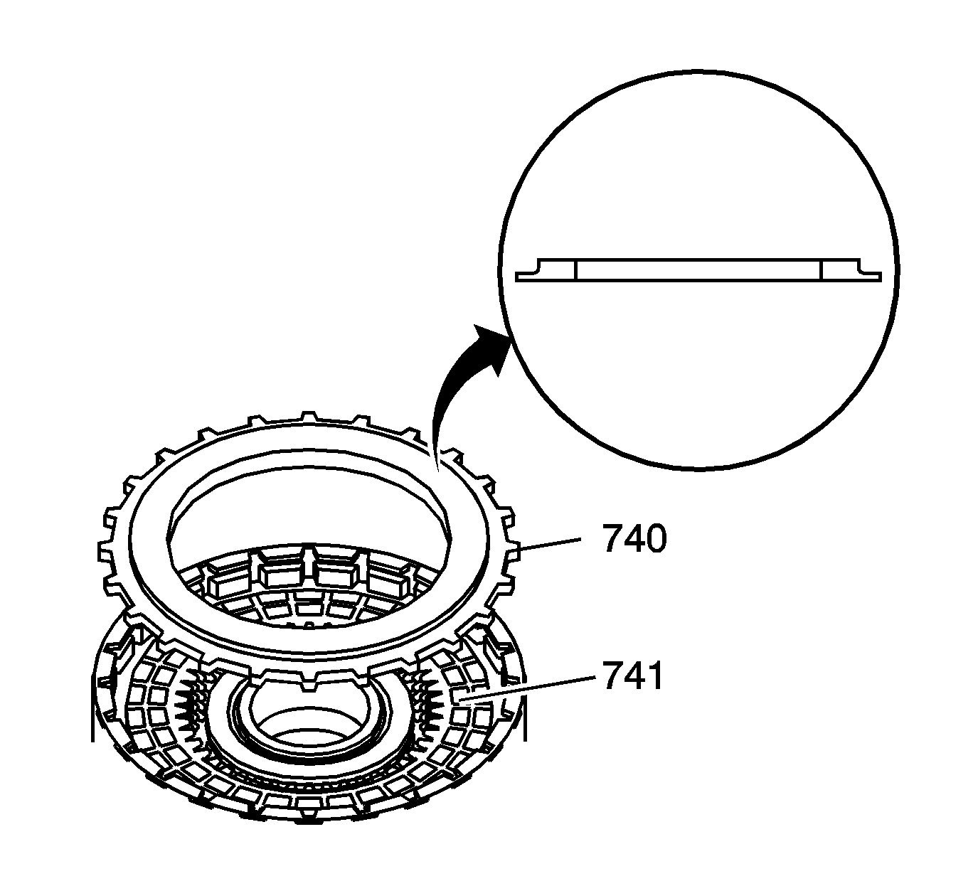
- Install the selective 2nd clutch backing plate (740) with the flat side facing the last 2nd clutch fiber plate (741) as shown in the insert.
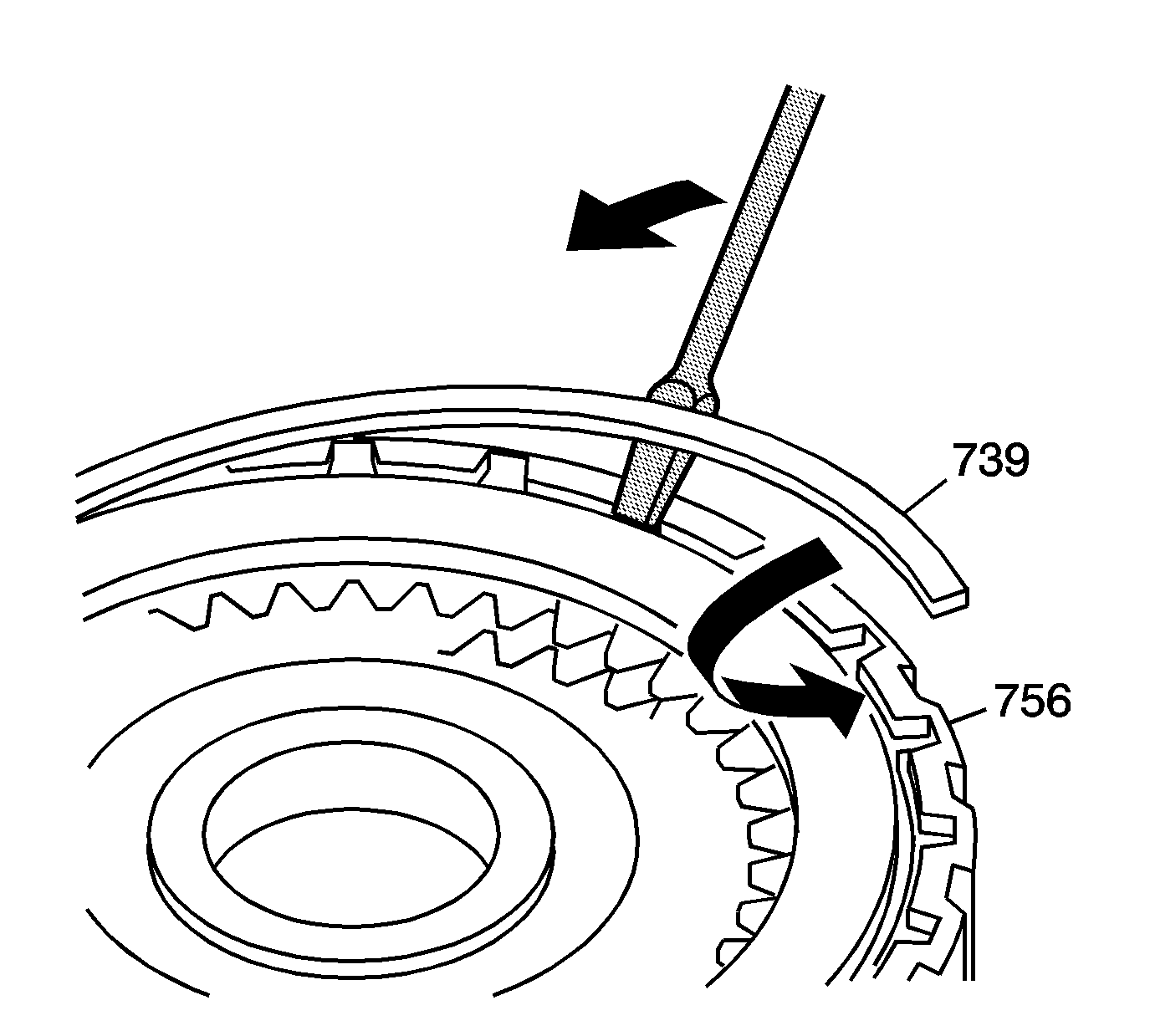
- Using J 28585 , install the 129 mm 2nd clutch backing plate retaining ring (739) into the groove in the 2nd clutch housing (756).
- Measure the clutch backing plate clearance. Refer to Clutch Backing Plate Clearance Measurement .
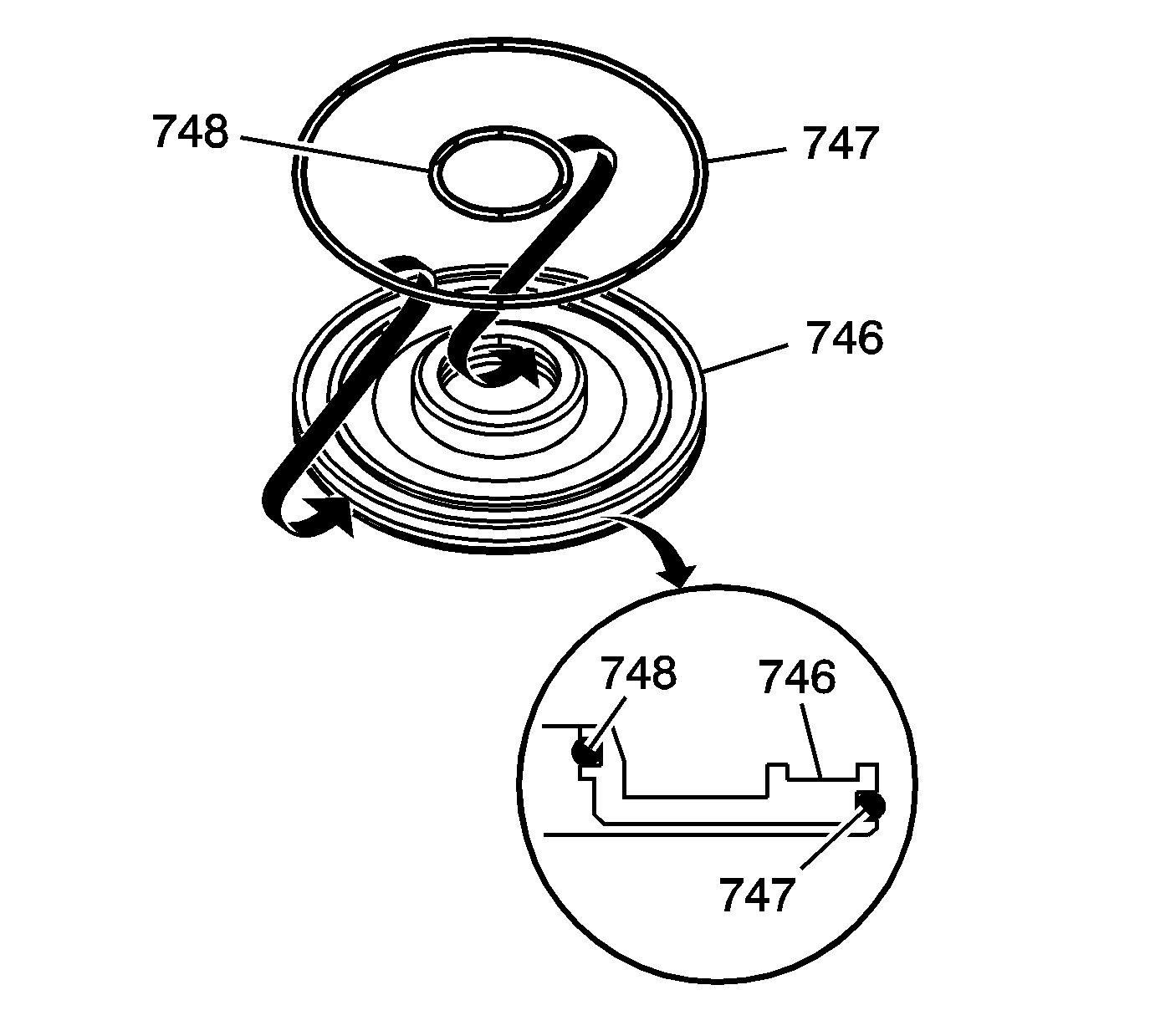
| 1.1. | Install the 2nd clutch inner O-ring seal (748). |
| 1.2. | Install the 2nd clutch outer O-ring seal (747). |
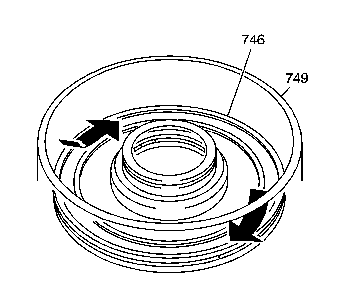
| • | Ensure proper seating. |
| • | Do not pinch the O-ring seal by installing the piston with excessive force. |
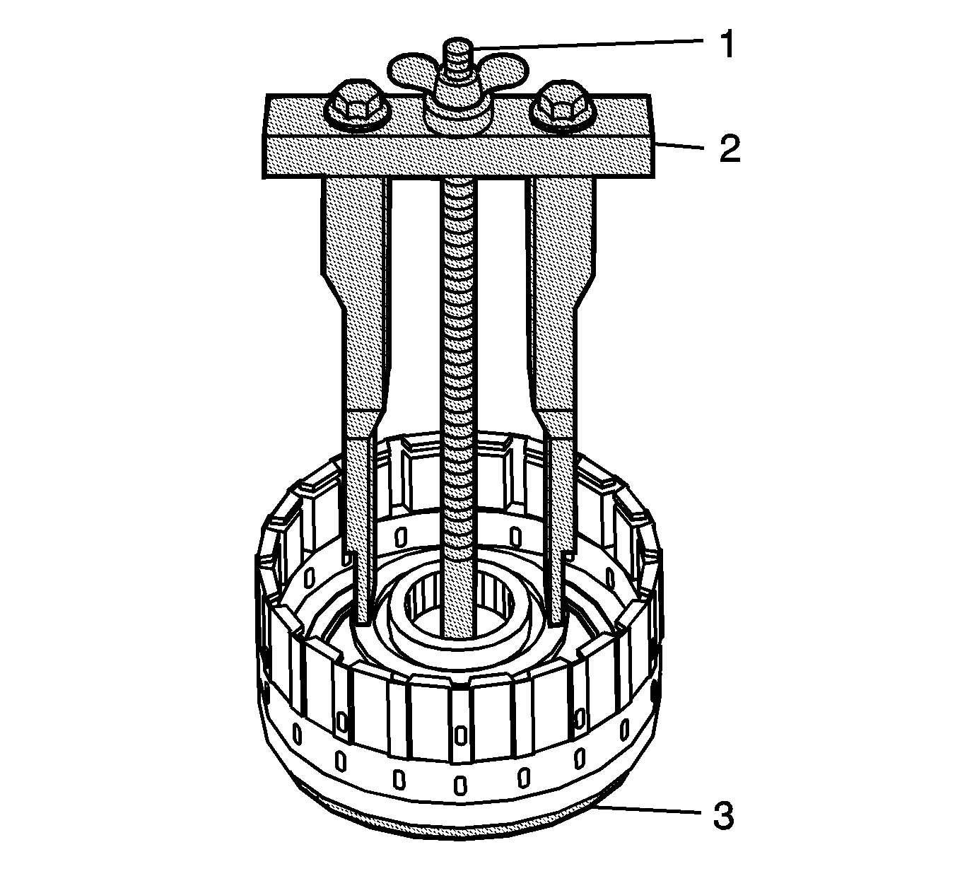
Important: Position the legs of the J 45124 on the spring retainer cap only where the spring is in contact with the cap.
| • | Adjust the legs of the J 45124 to have full contact with the clutch piston return spring retainer cap. |
| • | Do not place the legs on the spring retainer cap that is not supported by the spring. |
| • | Ensure the legs remain in position where the spring retainer cap is in contact with the spring. |

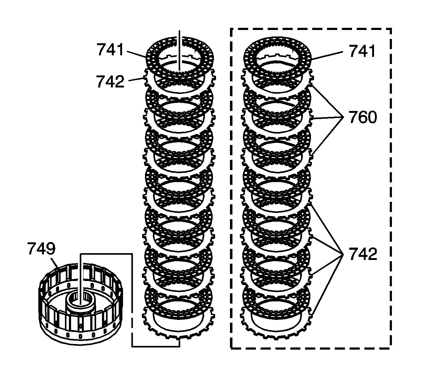
Important: If replacing the clutch plates, the clutch plate kit will include three 2nd clutch steel wave plates (760) and four 2nd clutch steel flat plates (742). The 2nd clutch assembly 1st design contains seven 2nd clutch steel flat plates (742). The 2nd design contains three 2nd clutch steel wave plates (760) and four 2nd clutch steel flat plates (742).
| • | 2nd clutch steel flat plate (742). |
| • | 2nd clutch fiber plate (741). |
| • | Continue to alternately install the above components. The 2nd clutch steel wave plates (760), if equipped, are installed in the top three positions. |
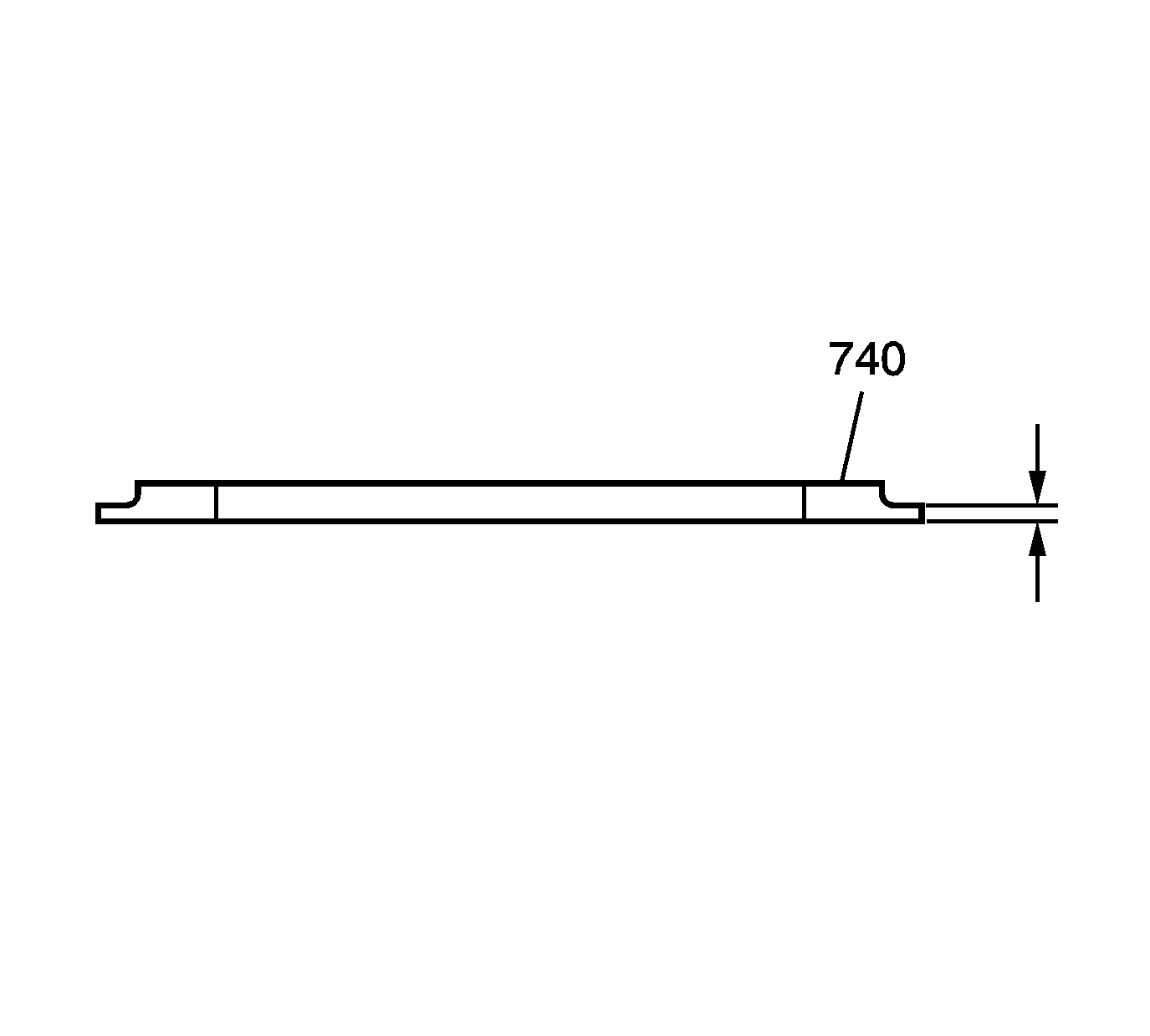
Important: The thickness of the backing plate (740) is measured at the outer thickness.
