Exhaust Manifold Pipe Replacement 3.5L (L66)
Removal Procedure
- Raise the vehicle on a hoist. Refer to Lifting and Jacking the Vehicle .
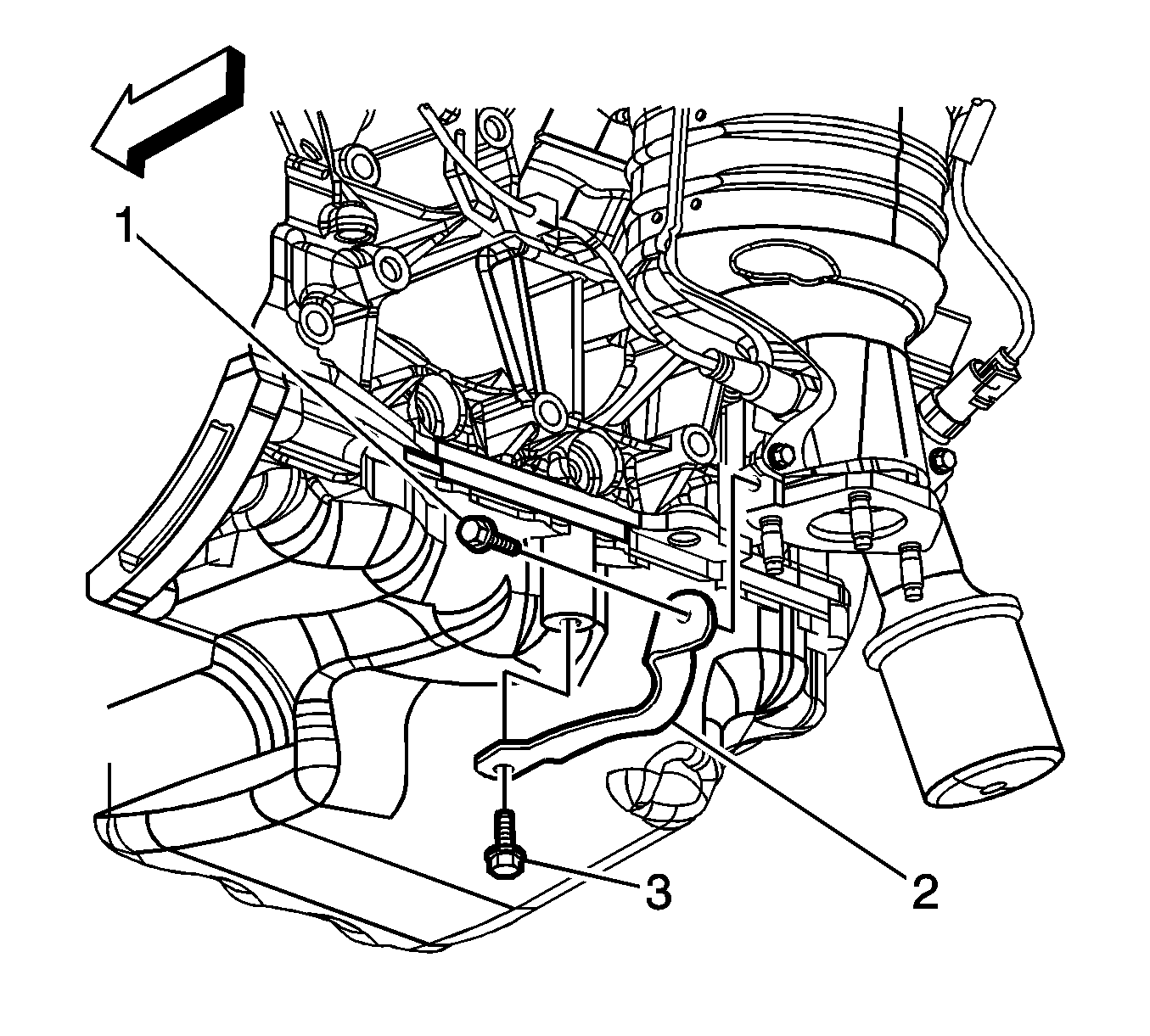
- Remove the oil pan bracket (2) and bolts (1, 3).
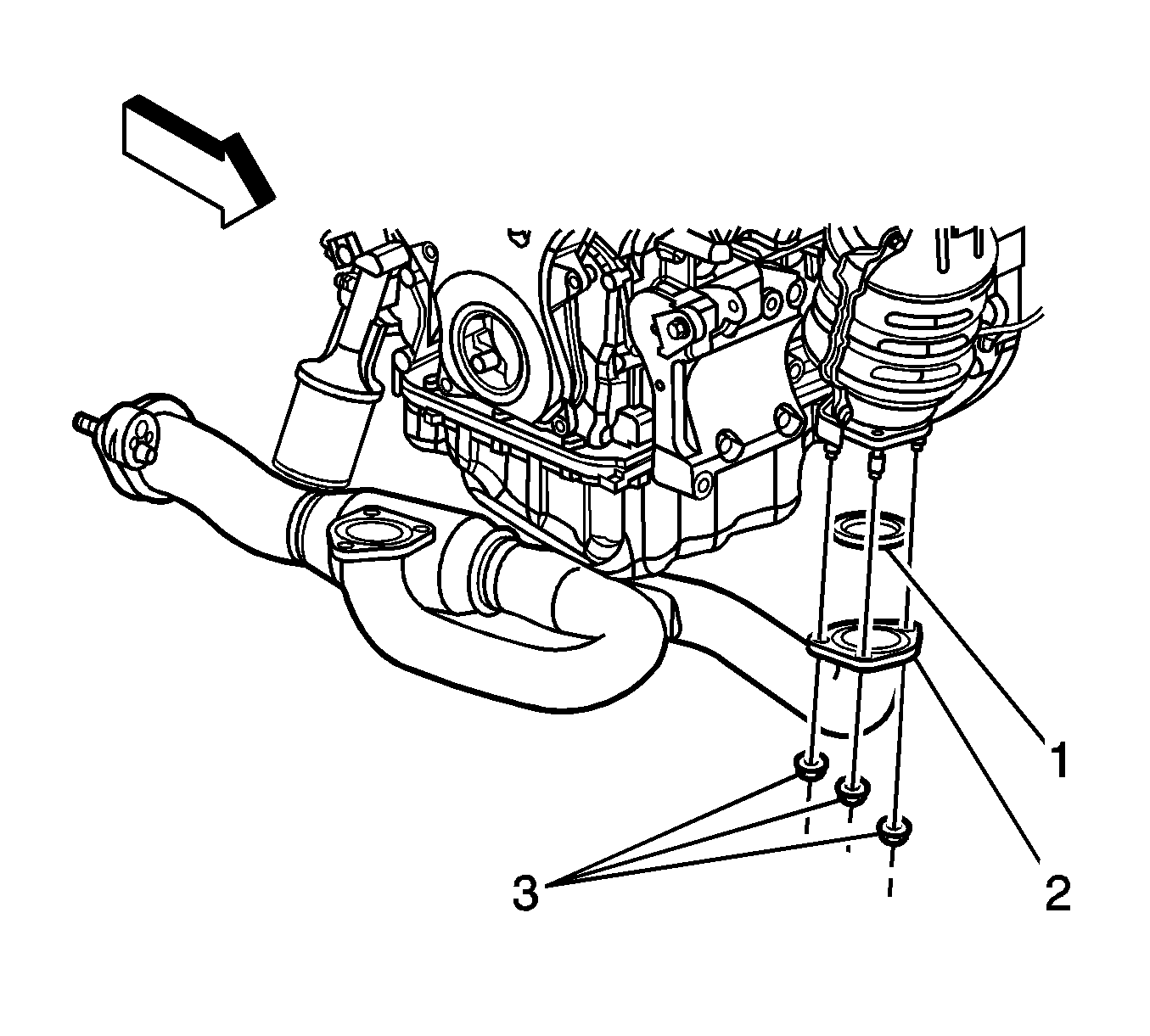
- Remove the exhaust pipe flange to the catalytic converter nuts (3) .
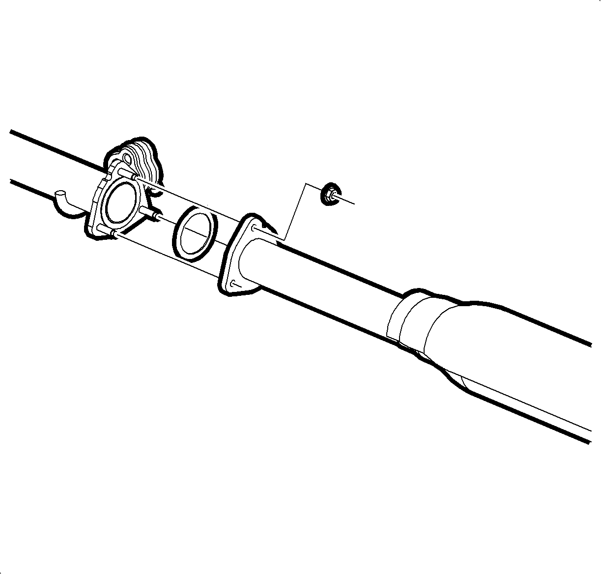
- Remove the exhaust pipe to mid muffler pipe nuts.
- Remove the front exhaust pipe.
- Fully remove and discard the used gaskets.
Installation Procedure
Notice: Excessive flexing of the exhaust pipe may damage the flex coupling. Limit flexing to 12 degrees.
- Position pipe into vehicle, and install new gaskets onto converter studs.
- Assemble exhaust pipe to converters, install new nuts and tighten .
- Install the new gasket (1) onto the exhaust pipe rear flange.
- Assemble the front pipe to rear pipe, install the nuts and tighten.
- Install the oil pan bracket (2) and bolts (1, 3) and tighten.
- Lower the vehicle. Refer to Lifting and Jacking the Vehicle .
- Start the engine and check for exhaust leaks.

Notice: Refer to Fastener Notice in the Preface section.
Tighten
Tighten the nuts to 18 N·m (13 lb ft).
Tighten
Tighten the front pipe-to-rear pipe nuts to 30 N·m (22 lb ft).

Tighten
Tighten the bolts to 20 N·m (14 lb ft).
Exhaust Manifold Pipe Replacement L61
Removal Procedure
Caution: Ensure that the vehicle is properly supported and squarely positioned. To help avoid personal injury when a vehicle is on a hoist, provide additional support for the vehicle on the opposite end from which the components are being removed.
Notice: Excessive flexing of the exhaust pipe may damage the flex coupling. Limit flexing to 12 degrees.
- Raise the vehicle on a hoist. Refer to Lifting and Jacking the Vehicle in General Information.
- Disconnect the electrical connector from the oxygen sensor (O2S).
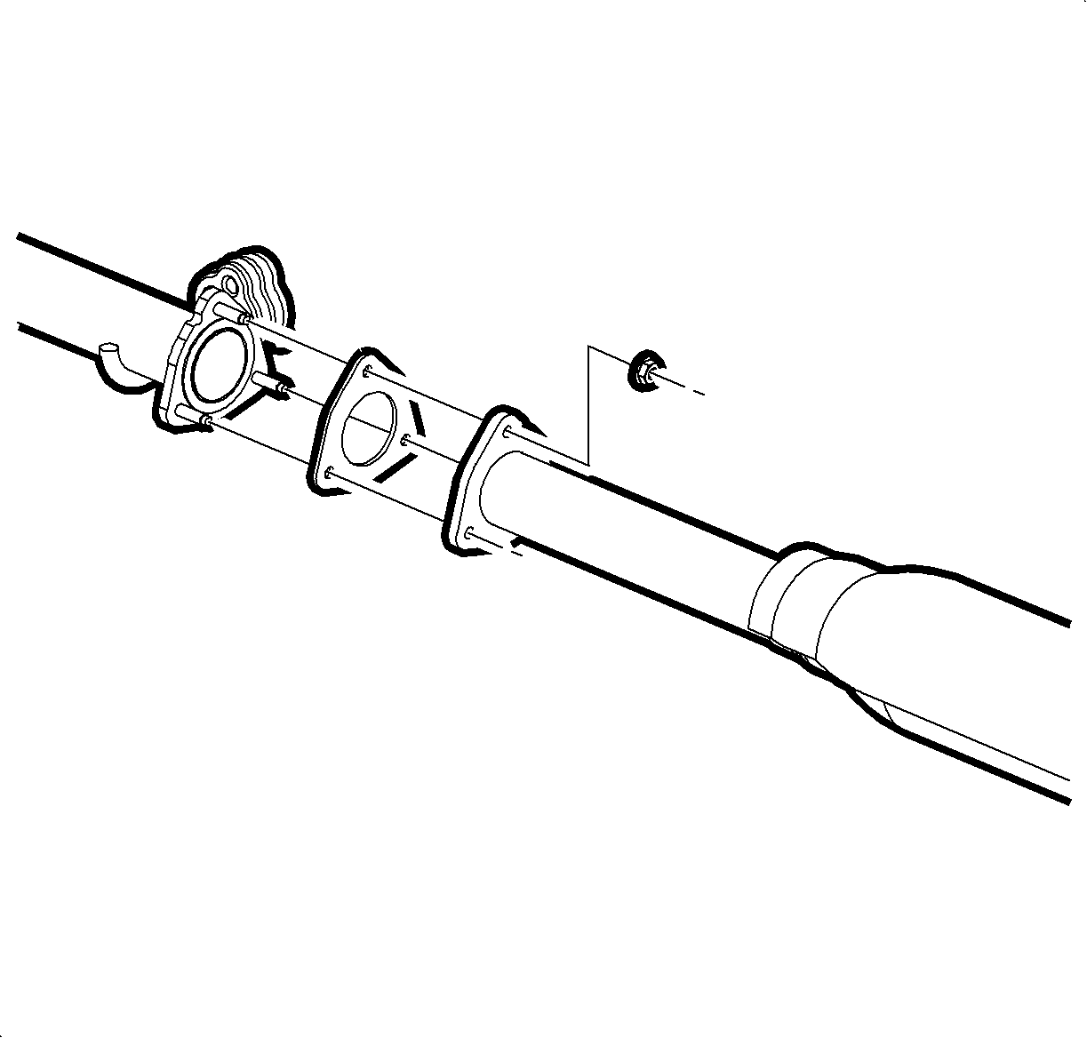
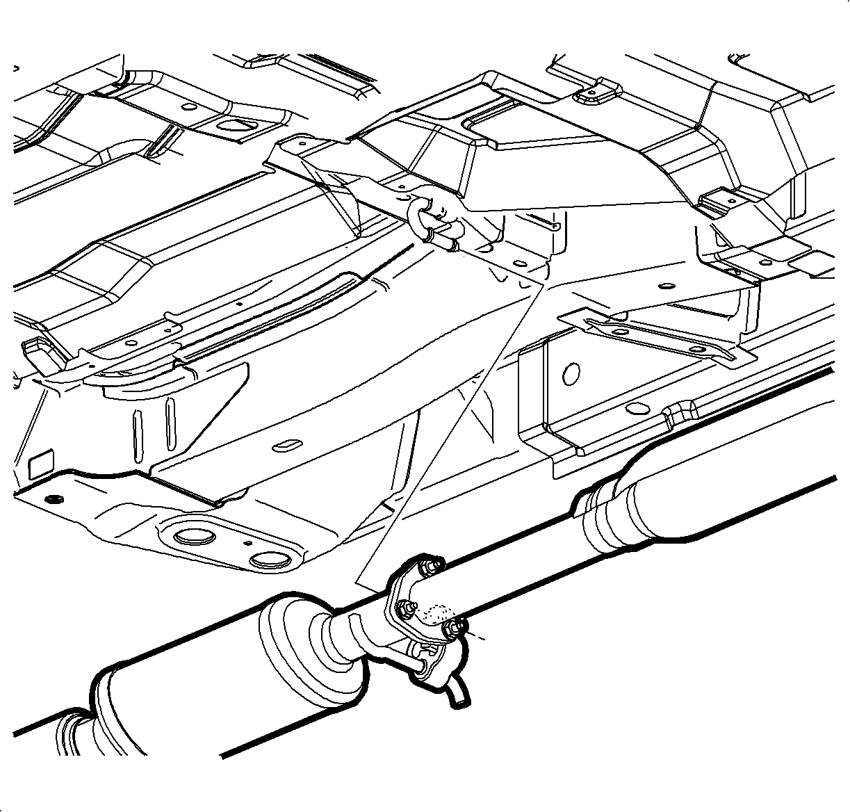
- Remove the nuts from the exhaust pipe flange to intermediate pipe and separate the flange from the studs.
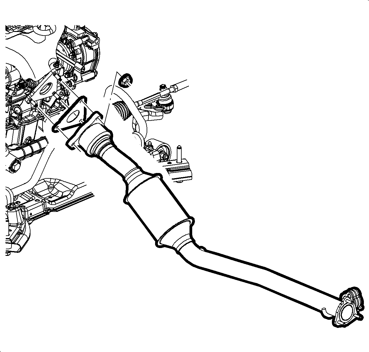
- Remove the nuts from the exhaust pipe flange to exhaust manifold.
- Separate the hanger from the rubber isolator.
- Separate the pipe flange from the manifold studs and remove the exhaust pipe.
- Fully remove and discard used gaskets.
- Remove the oxygen sensor if transferring to a new exhaust pipe.
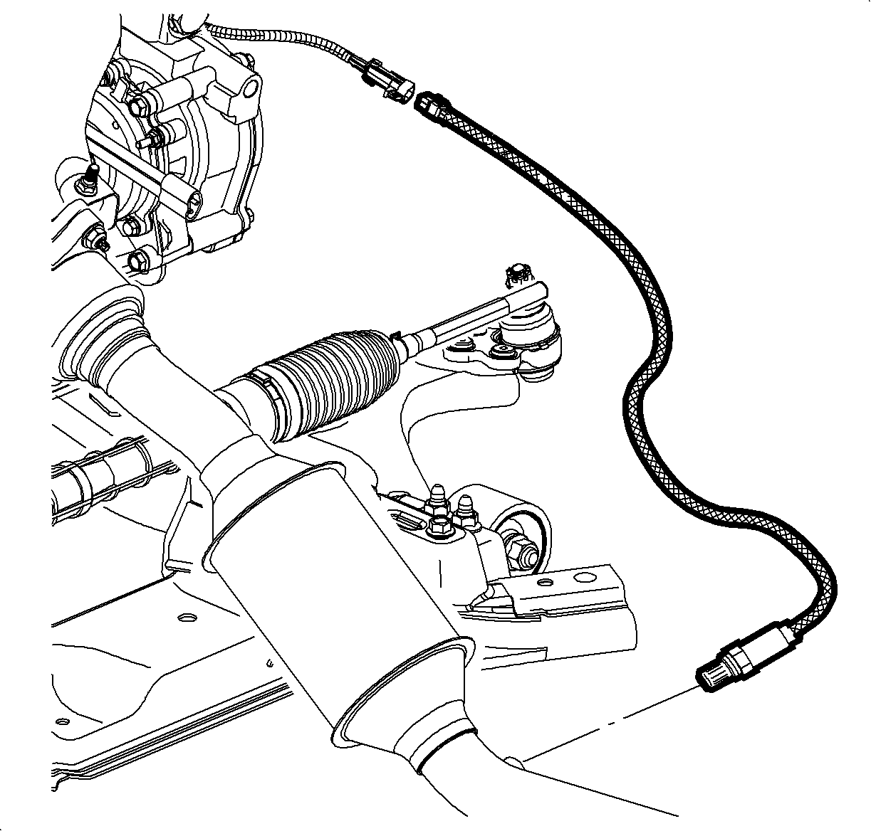
Important: Do not apply silicon products to the oxygen sensor.
Installation Procedure
- Install a new gasket onto the exhaust manifold studs.
- Assemble the exhaust pipe to manifold. Install new nuts and tighten.
- Install the new gasket onto the exhaust pipe flange.
- Assemble the exhaust pipe to intermediate pipe. Install new nuts and tighten.
- Lower the vehicle. Refer to Lifting and Jacking the Vehicle in General Information.
- Start the engine and check for exhaust leaks.

Notice: Refer to Fastener Notice in the Preface section.
Tighten
Tighten the nuts to 42 N·m (31 lb ft).

Tighten
Tighten the nuts to 30 N·m (22 lb ft).
