For 1990-2009 cars only
Removal Procedure
- With the tires in the straight forward position, remove the key from the ignition.
- Disconnect the negative battery cable. Refer to Battery Negative Cable Disconnection and Connection in Engine Electrical.
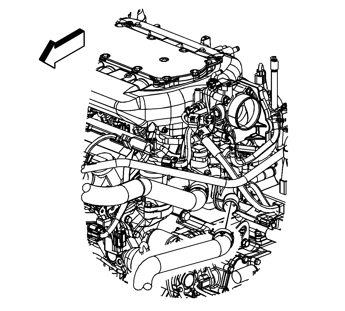
- Remove the air cleaner assembly. Refer to Air Cleaner Assembly Replacement in Engine Controls - 3.5L (L66).
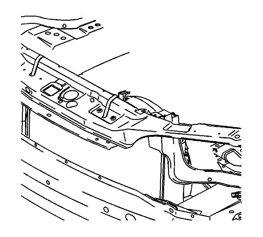
- Secure the cooling module to the upper body structure.
- Remove the battery and battery tray. Refer to Battery Tray Replacement in Engine Electrical.
- Disconnect the transmission shifter cable.
- Disconnect the wiring harness from the underhood junction block. Refer to Instrument Panel Electrical Center or Junction Block Replacement in Wiring Systems.
- Evacuate the A/C system. Refer to Refrigerant Recovery and Recharging in Heating, Ventilation, and Air Conditioning.
- Drain the cooling system. Refer to Cooling System Draining and Filling in Engine Cooling.
- Remove the powertrain control module (PCM). Refer to Powertrain Control Module Replacement in Engine Controls - 3.5L (L66).
- Remove the A/C low pressure tube at the front lift bracket.
- Disconnect the generator positive cable.
- Disconnect the A/C high pressure switch harness.
- Remove the A/C tube from the A/C compressor. Refer to Compressor Hose Assembly Replacement in Heating, Ventilation, and Air Conditioning.
- Disconnect the A/C line from the condenser to the compressor.
- Disconnect the coolant reservoir hose from the engine to reservoir.
- Disconnect the radiator inlet and outlet hoses from the engine.
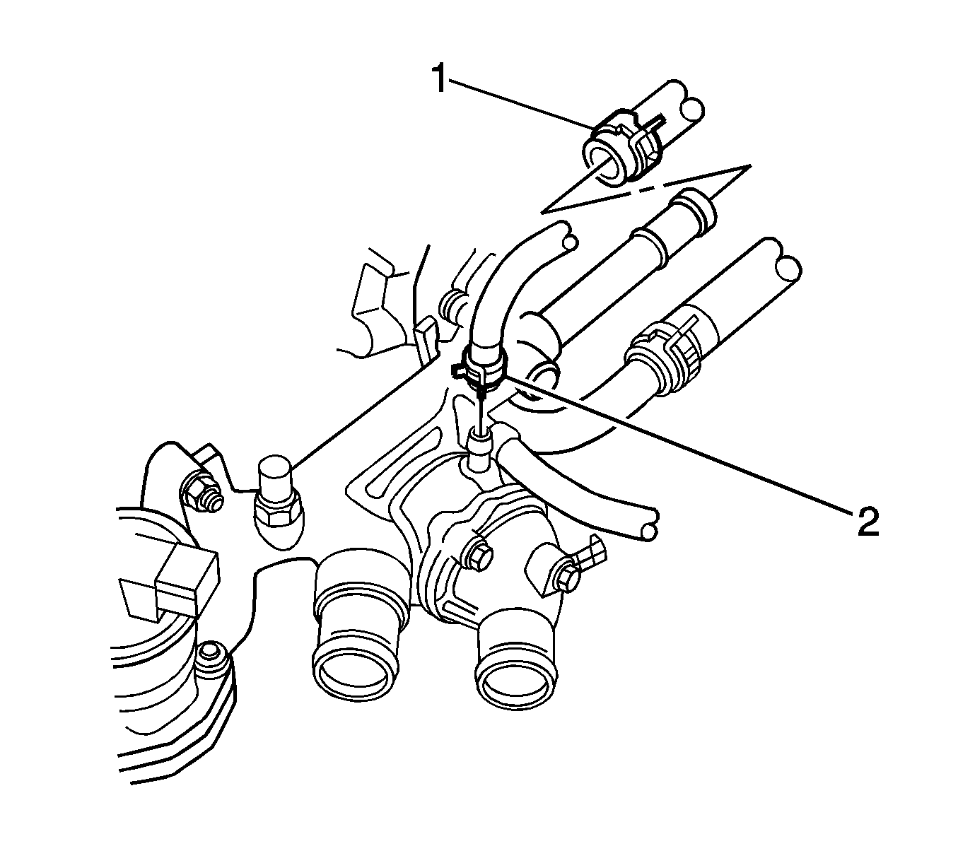
- Remove the inlet and outlet heater hoses (1, 2).
- Remove the starter positive cable.
- Relieve the fuel pressure. Refer to Fuel Pressure Relief in Engine Controls - 3.5L (L66).
- Disconnect the fuel feed line.
- Disconnect the fuel evaporative emission (EVAP) line.
- Raise and support the vehicle. Refer to Lifting and Jacking the Vehicle in General Information.
- Remove the lower transaxle-to-engine bolts.
- Remove the power take-off unit (PTU). Refer to Transfer Case Replacement in Transfer Case - MJ8.
- Remove the torque convertor inspection cover.
- Remove the torque convertor-to-flywheel bolts.
- Remove the front wheels. Refer to Tire and Wheel Removal and Installation in Tires and Wheels.
- Remove the left wheelhouse liner. Refer to Front Wheelhouse Liner Replacement in Body Front End.
- Disconnect the transmission cooler lines from the transmission and bracket. Refer to Oil Cooler Hose/Pipe Replacement .
- Remove the left and right tie rod ends from the steering knuckles. Refer to Rack and Pinion Outer Tie Rod End Replacement in Power Steering System.
- Remove the left and right stabilizer bar links. Refer to Stabilizer Shaft Link Replacement in Front Suspension.
- Disconnect the left and right lower ball joints. Refer to Lower Control Arm Ball Joint Replacement in Front Suspension.
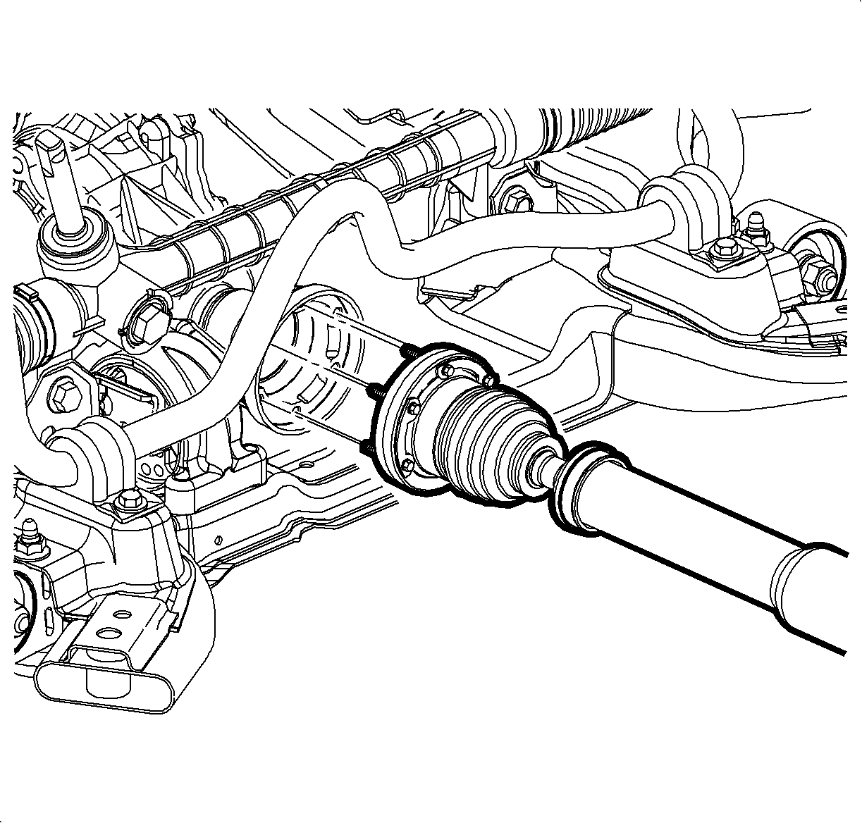
- Remove the left and right axle shaft nuts. Refer to Front Wheel Drive Shaft Replacement in Wheel Drive Shafts.
- Remove the propeller shaft. Refer to Propeller Shaft Replacement in Propeller Shaft.
- Disconnect the intermediate shaft from the steering gear. Refer to Intermediate Steering Shaft Replacement in Steering Wheel and Column.
- Remove the front exhaust pipe. Refer to Exhaust Manifold Pipe Replacement in Engine Exhaust.
- Remove the 3 front fender pushpins to allow the front fender to flex.
- Use a paint pen or magic marker to mark the frame to the body position.
- Support the engine in the cradle with wood blocks.
- Disconnect the front engine mount from the body. Refer to Engine Mount Replacement - Right Side in Engine Mechanical - 3.5L (L66).
- Position the engine support table under the powertrain assembly.
- With the table positioned, fully raise the table to contact with the powertrain assembly.
- Remove the cradle bolts.
- Slowly lower the table to the floor.
- Remove the starter.
- Remove the following components:
- Remove the transmission mount from the transmission. Refer to Transmission Rear Mount Replacement .
- Remove the rear transmission mount bracket. Refer to Transmission Rear Mount Bracket Replacement .
- Separate the transmission from the engine.
- Remove the transfer case, if equipped. Refer to Transfer Case Replacement .
Important: In order to prevent possible SIR system deployment, do not attempt to rotate the steering shaft.
Important: During the powertrain removal, support the vehicle by placing a jack at the rear of the vehicle.
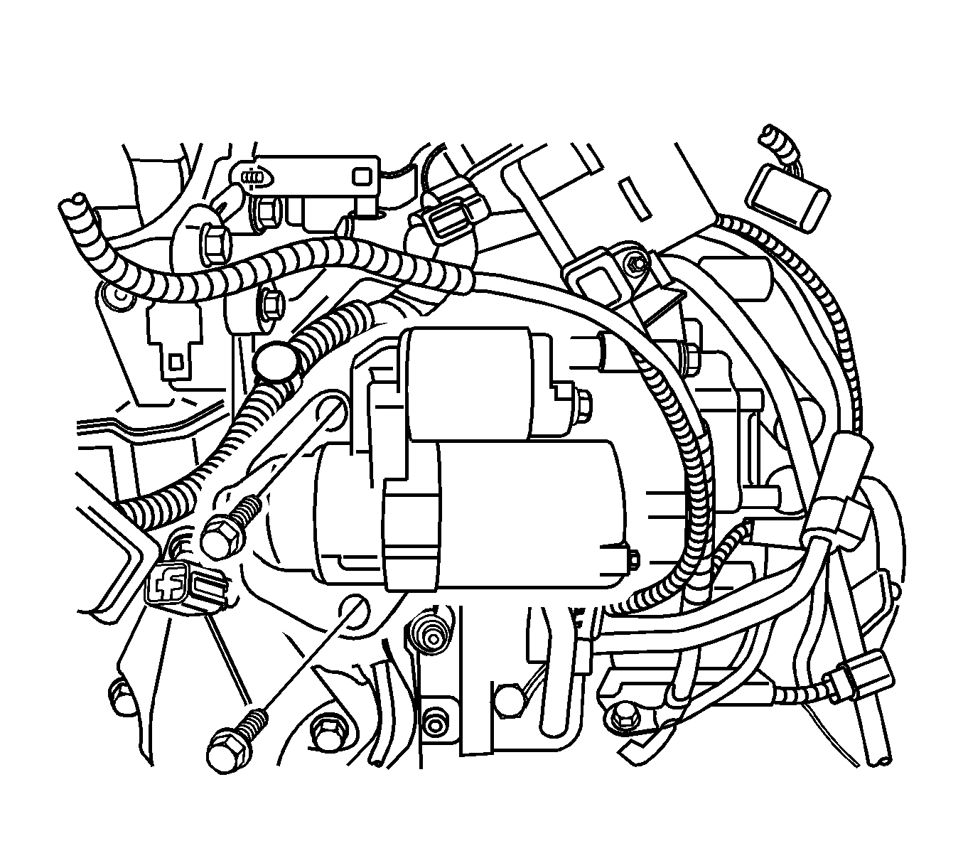
| 47.1. | Remove the transmission shift cable bracket. |
| 47.2. | Remove the Park/Neutral position switch. Refer to Park/Neutral Position Switch Replacement . |
| 47.3. | Remove the transmission vent hose. |
Installation Procedure
- Align the transmission to the engine.
- Install the transmission mount bracket. Refer to Transmission Rear Mount Bracket Replacement .
- Install the transmission mount to the engine. Refer to Transmission Rear Mount Replacement .
- Install the following components:
- Install the starter. Refer to Starter Motor Replacement in Engine Electrical.
- Install the powertrain assembly to the vehicle.
- Install the cradle bolts. Refer to Frame Replacement in Frame and Underbody.
- Remove the engine support table.
- Install the front engine mount bolts to the body. Refer to Engine Mount Replacement - Right Side in Engine Mechanical - 3.5L (L66).
- Remove the wood blocks from the cradle.
- Install the lower transaxle-to-engine bolts.
- Install the PTU. Refer to Transfer Case Replacement in Transfer Case - MJ8.
- Install the torque convertor-to-flywheel bolts.
- Install the torque convertor inspection cover.
- Install the 3 front fender pushpins
- Install the front exhaust pipe. Refer to Exhaust Manifold Pipe Replacement in Engine Exhaust.
- Connect the intermediate shaft from the steering gear. Refer to Intermediate Steering Shaft Replacement in Steering Wheel and Column.
- Install the propeller shaft. Refer to Propeller Shaft Replacement in Propeller Shaft.
- Install the left and right axle shaft nuts. Refer to Front Wheel Drive Shaft Replacement in Wheel Drive Shafts.
- Connect the left and right lower ball joints. Refer to Lower Control Arm Ball Joint Replacement in Front Suspension.
- Install the left and right stabilizer bar links. Refer to Stabilizer Shaft Link Replacement in Front Suspension.
- Install the left and right tie rod ends to the steering knuckles. Refer to Rack and Pinion Outer Tie Rod End Replacement in Power Steering System.
- Connect the transmission cooler lines to the transmission and bracket. Refer to Oil Cooler Hose/Pipe Replacement .
- Install the left wheelhouse liner. Refer to Front Wheelhouse Liner Replacement in Body Front End.
- Install the front tires. Refer to Tire and Wheel Removal and Installation in Tires and Wheels.
- Lower the vehicle.
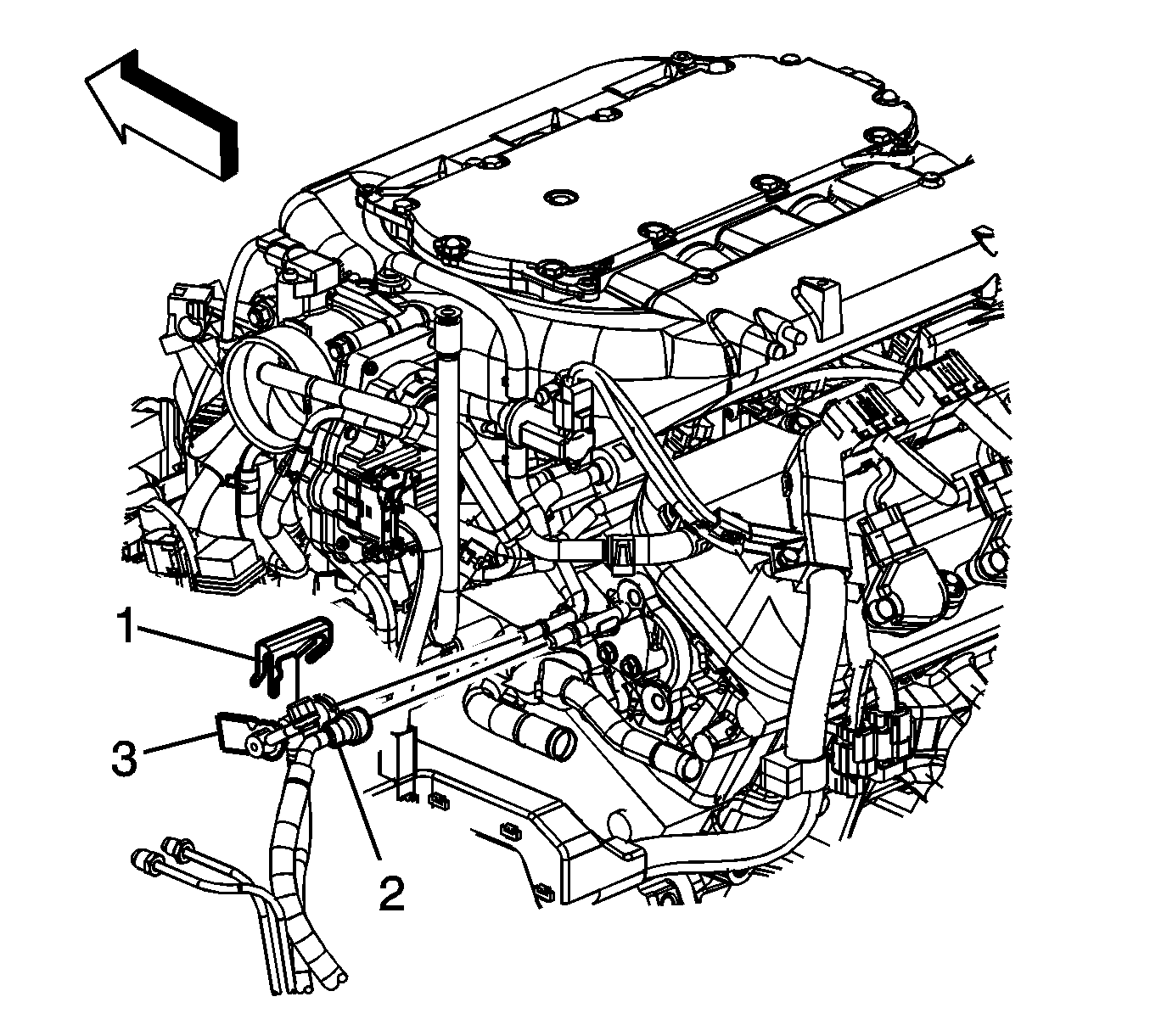
- Install the fuel EVAP line (3).
- Connect the fuel feed line (2). Refer to Fuel Hose/Pipes Replacement - Chassis in Engine Mechanical - 3.5L (L66).
- Install the starter positive cable.
- Install the inlet and outlet heater hoses.
- Connect the inlet and outlet radiator hoses to the engine.
- Install the A/C tube to the A/C compressor. Refer to Compressor Hose Assembly Replacement in Heating, Ventilation, and Air Conditioning.
- Connect the coolant reservoir hose from engine to reservoir.
- Connect the A/C line from the condenser to the compressor.
- Connect the A/C high pressure switch harness.
- Connect the generator positive cable and nut.
- Install the A/C lower pressure tube at the front lift bracket. Refer to Liquid Line Replacement in Heating, Ventilation, and Air Conditioning.
- Install the PCM. Refer to Powertrain Control Module Replacement in Engine Controls - 3.5L (L66).
- Connect the radiator inlet and outlet hoses to the engine.
- Fill the vehicle with coolant. Refer to Cooling System Draining and Filling in Engine Cooling.
- Connect the wiring harness to the underhood junction block. Refer to Instrument Panel Electrical Center or Junction Block Replacement in Wiring Systems.
- Connect the transmission shifter cable.
- Remove the cooling module support.
- Install the battery tray and battery. Refer to Battery Tray Replacement in Engine Electrical.
- Install the air cleaner assembly. Refer to Air Cleaner Assembly Replacement in Engine Controls - 3.5L (L66).
- Install the air outlet duct assembly. Refer to Air Cleaner Resonator Outlet Duct Replacement in Engine Mechanical - 3.5L (L66).
- Connect the negative battery cable. Refer to Battery Negative Cable Disconnection and Connection in Engine Electrical.
- Perform the idle learn procedure. Refer to Idle Learn in Engine Controls - 3.5L (L66).
Notice: Refer to Fastener Notice in the Preface section.
| 4.1. | Install the transmission vent hose. |
| 4.2. | Install the Park/Neutral position switch. Refer to Park/Neutral Position Switch Replacement . |
| 4.3. | Install the transmission shift cable bracket and bolts. |
Tighten
Tighten the bolts to 10 N·m (89 lb in).

Tighten
Tighten the bolts to 64 N·m (47 lb ft).
Tighten
Tighten the bolts to 12 N·m (106 lb in).
Tighten
Tighten the bolts to 12 N·m (106 lb in).
Tighten
Tighten the starter cable to 12 N·m (106 lb in).
Tighten
Tighten the nut to 12 N·m (106 lb in).


