For 1990-2009 cars only
Special Tools
J 45059 Angle Meter
Removal Procedure
- Remove the engine. Refer to Engine Replacement .
- Remove the crankshaft balancer. Refer to Crankshaft Balancer Removal
- Remove the front cover. Refer to Engine Front Cover and Oil Pump Removal.
- Remove the engine oil pan. Refer to Oil Pan Removal .
- Remove the crankshaft position sensor.
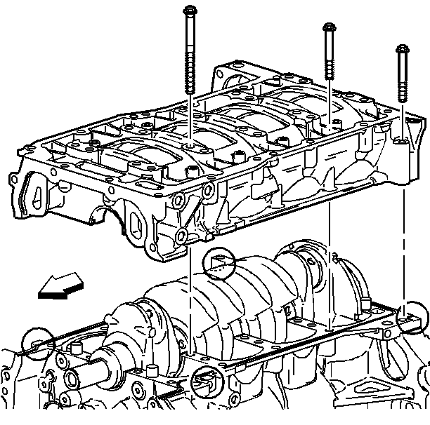
- Remove the 3 perimeter bolts.
- Remove and discard the crankshaft bearing bolts.
- Using the pry points and an appropriate prying tool, gently separate the upper and lower crankcase.
- Clean the sealing material from the engine block and lower the crankcase.

Important: Do not forget the 2 outside rear bolts.
Installation Procedure
- Apply oil to the crankshaft bearing surfaces.
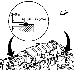
- Apply a 2-5 mm (0.08-0.20 in) bead (a) of sealer GM P/N 12378521 (Canadian P/N 88901148) to the surface of the engine block-to-lower crankcase mating surface.
- Install the lower crankcase.
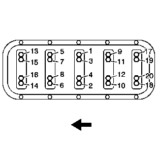
- Install the NEW crankshaft bearing bolts in sequence finger tight.
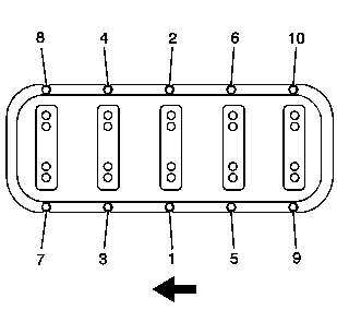
- Tighten the lower crankcase perimeter bolts in sequence.
- Install the crankcase position sensor.
- Install the front cover. Refer to Engine Front Cover and Oil Pump Installation.
- Install the crankshaft balancer. Refer to Crankshaft Balancer Installation.
- Install the engine oil pan. Refer to Oil Pan Installation .
- Install the engine. Refer to Engine Replacement.


Tap gently into place with a suitable tool, if necessary. Ensure it is aligned properly on the dowels.
Notice: Refer to Fastener Notice in the Preface section.

| 4.1. | Tighten the crankshaft bearing bolts in sequence. |
Tighten
Tighten the crankshaft bearing bolts to 20 N·m (15 lb ft).
| 4.2. | Tighten the crankshaft bearing bolts in sequence using the J 45059 . |
Tighten
Tighten the crankshaft bearing bolts to 70 degrees using the
J 45059 .

Tighten
Tighten the lower crankcase perimeter bolts to 25 N·m (18 lb ft).
