For 1990-2009 cars only
Removal Procedure
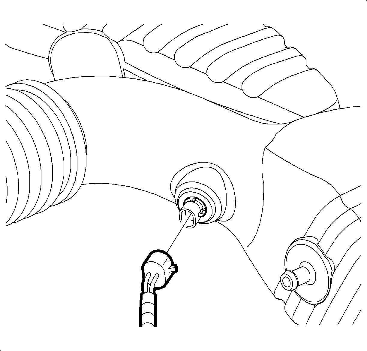
- Disconnect the intake air temperature (IAT) sensor connector.
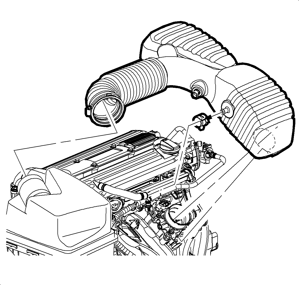
- Loosen the clamp at the air cleaner assembly.
- Remove the push pin attachment from the outlet resonator/duct assembly to support bracket.
- Loosen the clamp at the throttle body assembly.
- Disconnect the positive crankcase ventilation (PCV) fresh air vent hose at the outlet duct assembly.
- Remove the outlet resonator/duct assembly.
- Cover the throttle body opening with a shop towel and use the shop air to remove any dirt at the base of the throttle body to intake and intake manifold to cylinder head.
- Disconnect the harness connector at the throttle body.
- Remove the throttle body bolts.
- Remove the throttle body.
- Remove the throttle body gasket.
- Block the intake manifold opening with a clean shop towel to prevent dirt from entering.
- Remove the engine control module (ECM) bolts and set the ECM aside.
- Disconnect the electrical connectors (injector harness) attach to the side of the manifold and position the harness away from the manifold and set aside.
- Disconnect the manifold absolute pressure (MAP) sensor.
- Disconnect the purge hose.
- Disconnect the electrical attachment bolt at bottom of the manifold.
- Raise the vehicle. Refer to Lifting and Jacking the Vehicle .
- Disconnect the electrical harness clips at the bottom of the manifold.
- Lower the vehicle.
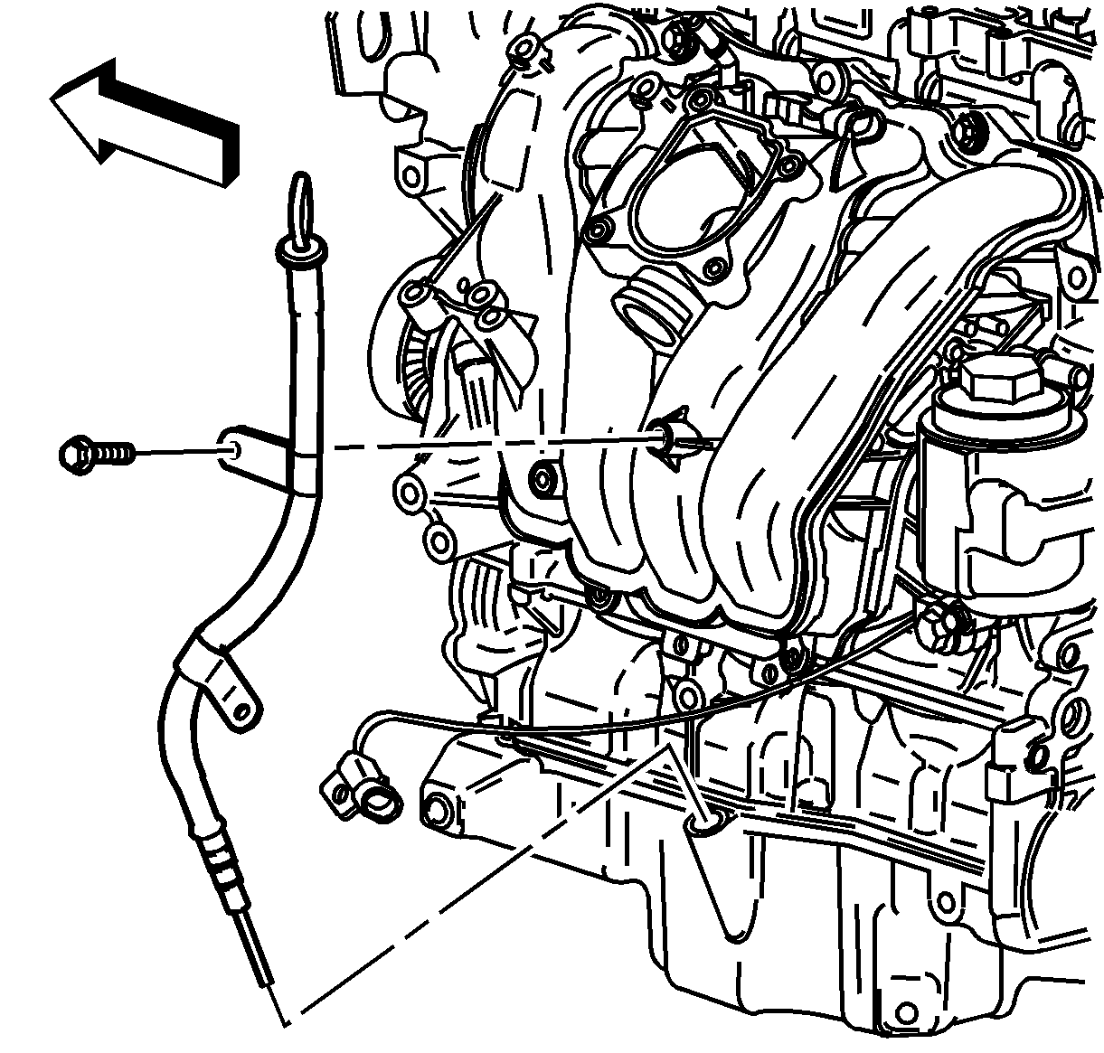
- Remove the oil level tube bolt and rotate tube away from the manifold.
- Remove the intake manifold bolts and nuts.
- Pull the manifold away from the cylinder head.
- Disconnect the brake booster hose at the manifold by releasing the white tab.
- Remove the intake manifold assembly.
- Remove the intake manifold gasket and discard.
- Block the intake manifold to cylinder head openings with a clean shop towel to prevent dirt from entering.
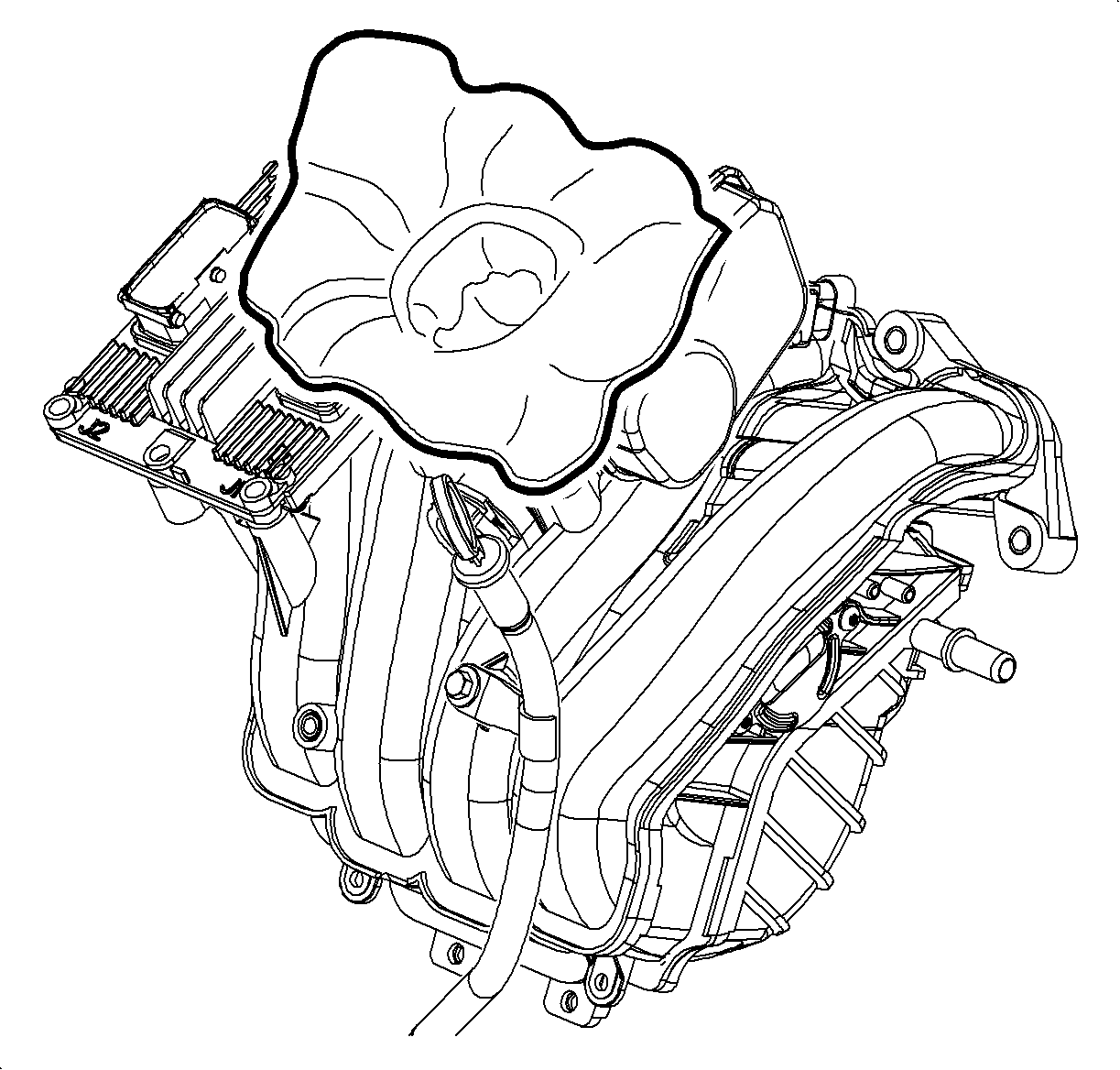
Important: The mating surfaces between the throttle body to manifold and manifold to cylinder head should be free from dirt and foreign material before servicing.
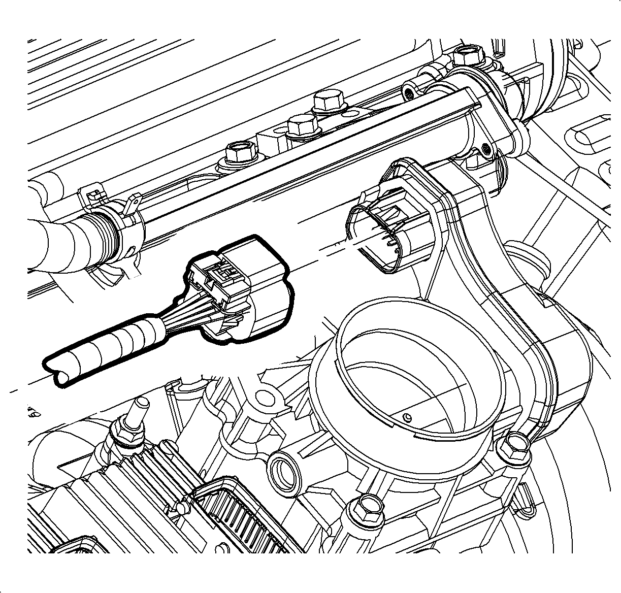
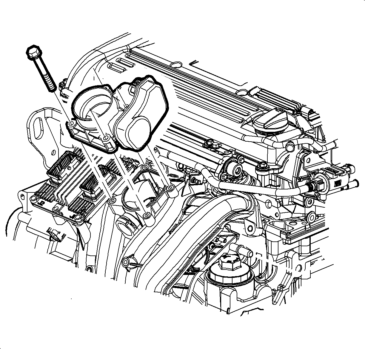
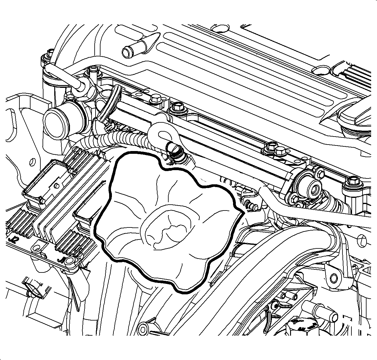
Notice: Cover the intake manifold opening with a shop towel whenever the throttle body is removed to prevent foreign material entry.
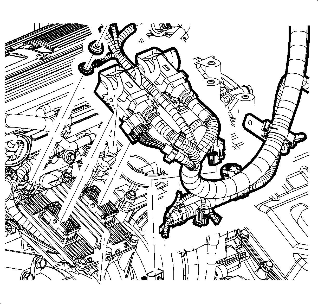
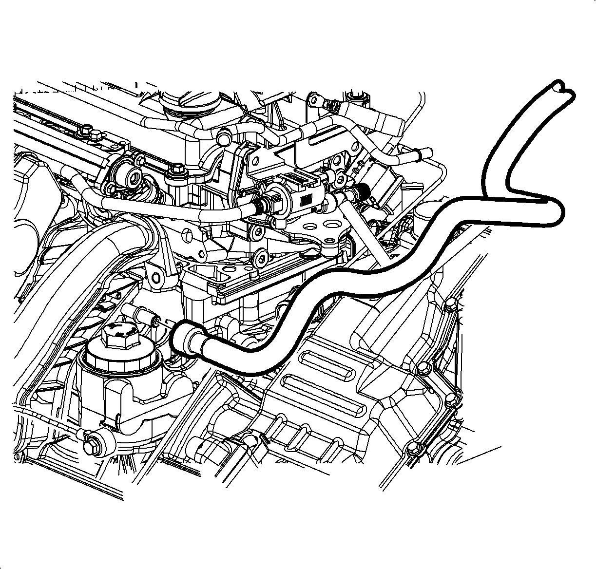
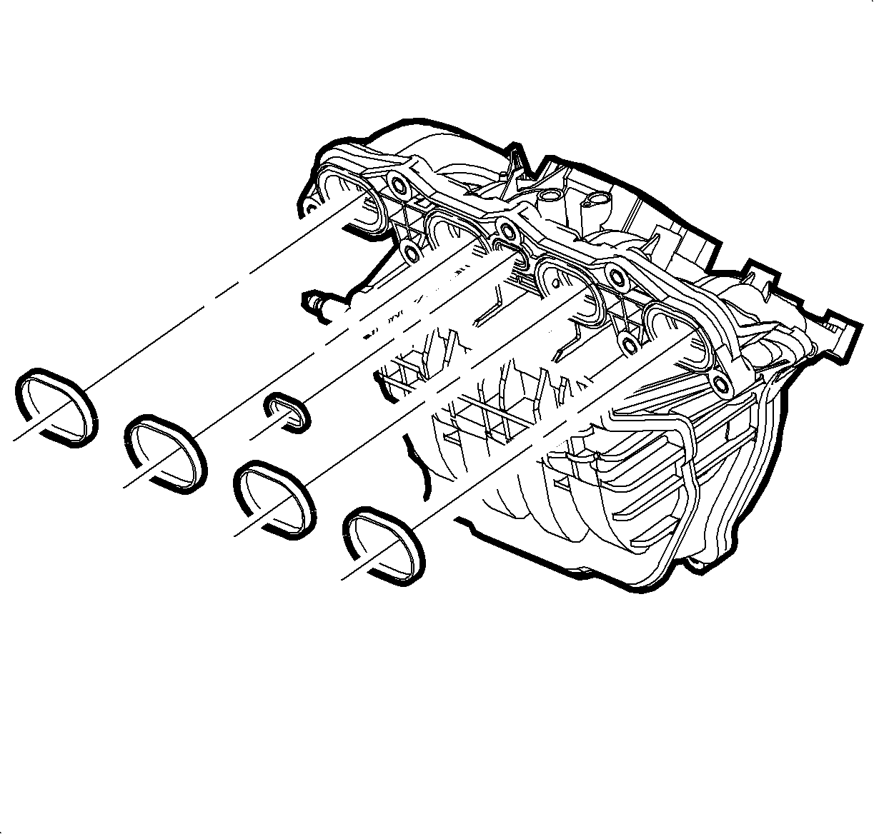
Important: The intake manifold gasket is not reusable.
Notice: Cover the cylinder head ports with a shop towel to prevent foreign material from entering the cylinder head.
Installation Procedure
- Remove the shop towel from the throttle body opening.
- Install the intake manifold gasket to manifold.
- Connect the brake booster hose to intake manifold.
- Install the intake manifold to cylinder head.
- Install the intake manifold bolts and nuts.
- Install the oil level indicator tube assembly and bolt.
- Install the ECM assembly and bolts.
- Attach the electrical harness to the bottom of the intake manifold.
- Connect the electrical connector at the ECM, injector harness and MAP sensor.
- Connect the purge hose.
- Remove the shop towel from the throttle body opening.
- Install the new throttle body gasket.
- Install the throttle body assembly and bolts.
- Connect the throttle body electrical connector.
- Position the outlet resonator/duct assembly into position.
- Connect the PCV fresh air vent hose assembly.
- Tighten the clamp at the throttle body assembly.
- Position the outlet resonator/duct assembly up with support bracket and install the push-pin.
- Tighten the clamp at the air cleaner assembly.
- Connect the intake air temperature (IAT) sensor connector.


Notice: Refer to Fastener Notice in the Preface section.
Tighten
| • | Tighten the intake manifold-to-cylinder head bolts L61 to 10 N·m (89 lb in). |
| • | Tighten the intake manifold-to-cylinder head nuts L61 to 10 N·m (89 lb in). |

Tighten
Tighten the oil level indicator tube-to-intake manifold bolt L61 to 10 N·m (89 lb in).


Tighten
Tighten the throttle body-to-intake manifold bolts L61 to 10 N·m (89 lb in).


