For 1990-2009 cars only
Removal Procedure
- Remove the drive belt. Refer to Drive Belt Replacement.
- Remove the oil level indicator tube. Refer to Oil Level Indicator and Tube Replacement.
- Install the engine support fixture. Refer to Engine Support Fixture.
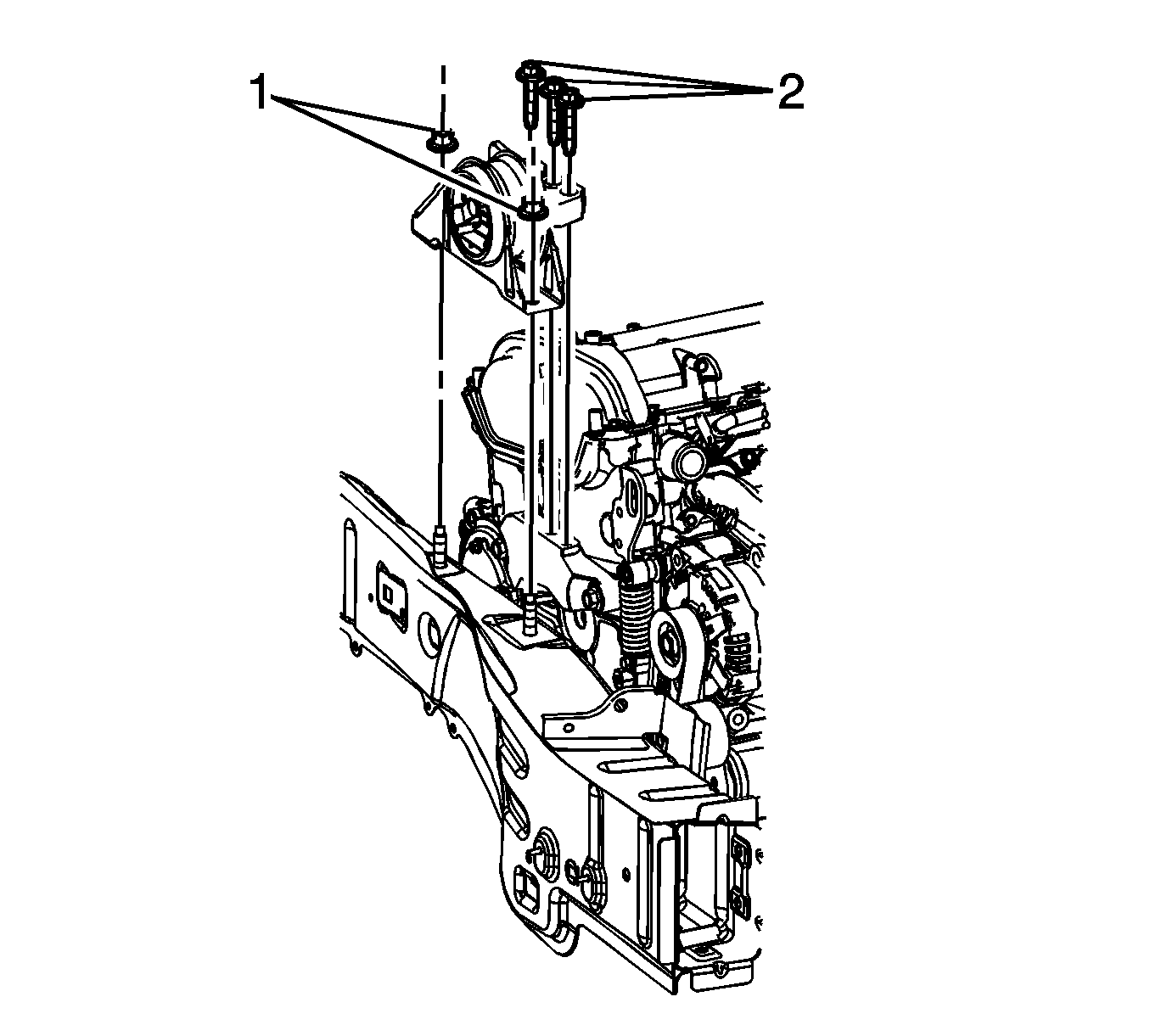
- Remove engine mount to bracket bolts (2).
- Remove the engine mount to side rail nuts (1).
- Remove the engine mount from the engine compartment.
- Using the engine support fixture, raise the engine approximately 3 inches.
- Raise and support the vehicle. Refer to Lifting and Jacking the Vehicle.
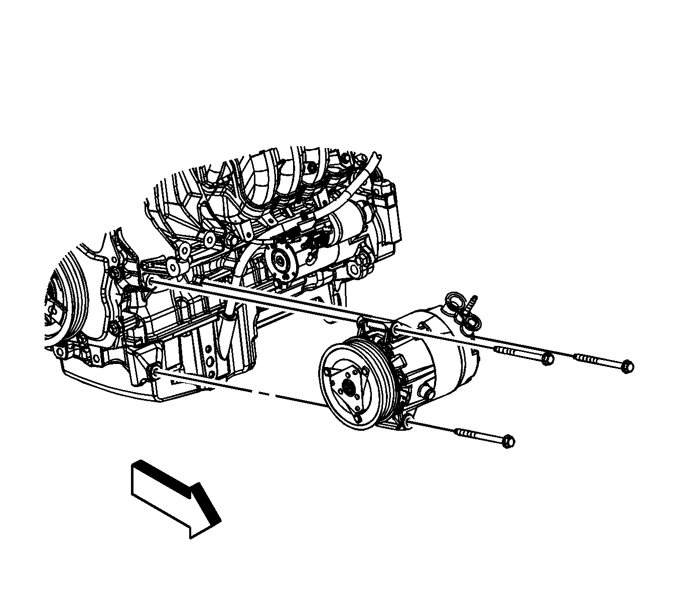
- Loosen the upper air conditioning (A/C) compressor bolts.
- Remove the lower A/C compressor bolt.
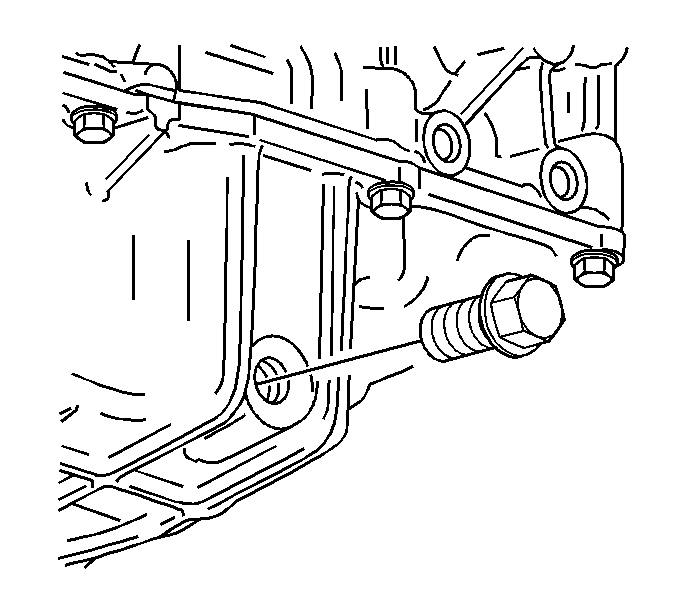
- Place a suitable drain pan under the oil pan drain plug.
- Remove the oil pan drain plug.
- Drain the engine oil.
- Reinstall the oil pan drain plug until snug.
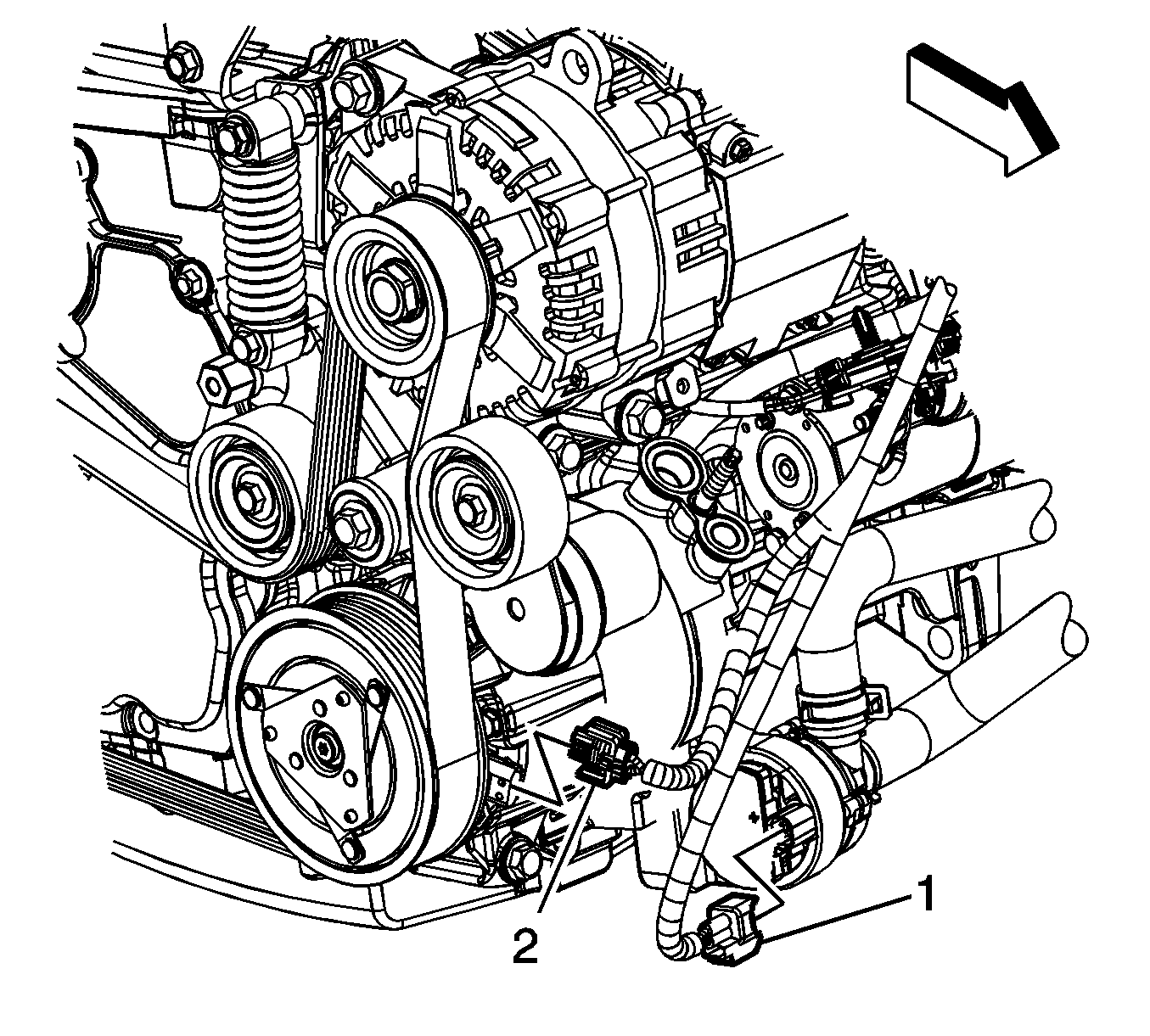
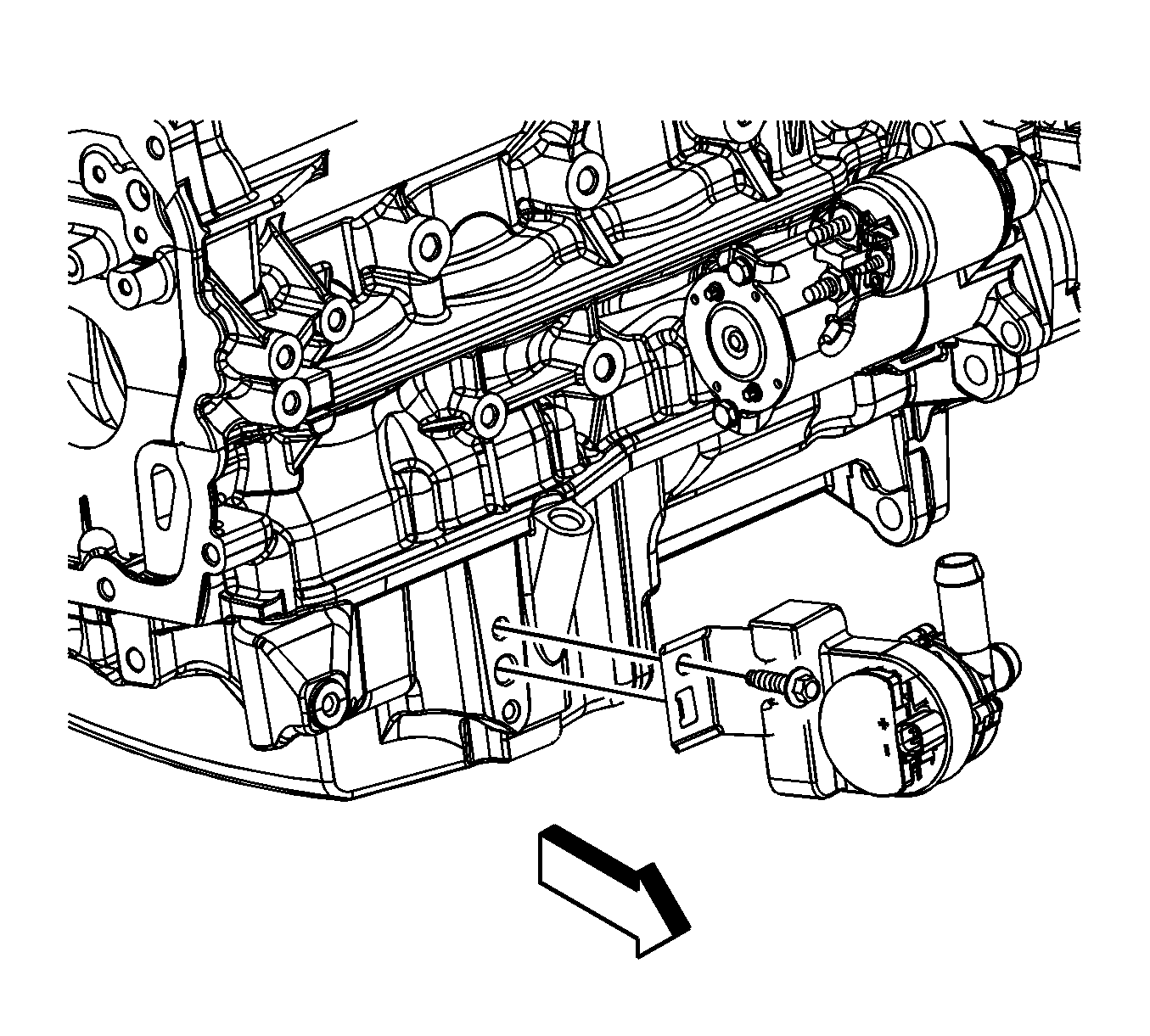
- Disconnect the engine wiring harness electrical connector (1) from the generator control module coolant pump.
- Remove the generator control module coolant pump bolt.
- Remove the generator control module coolant pump from the oil pan.
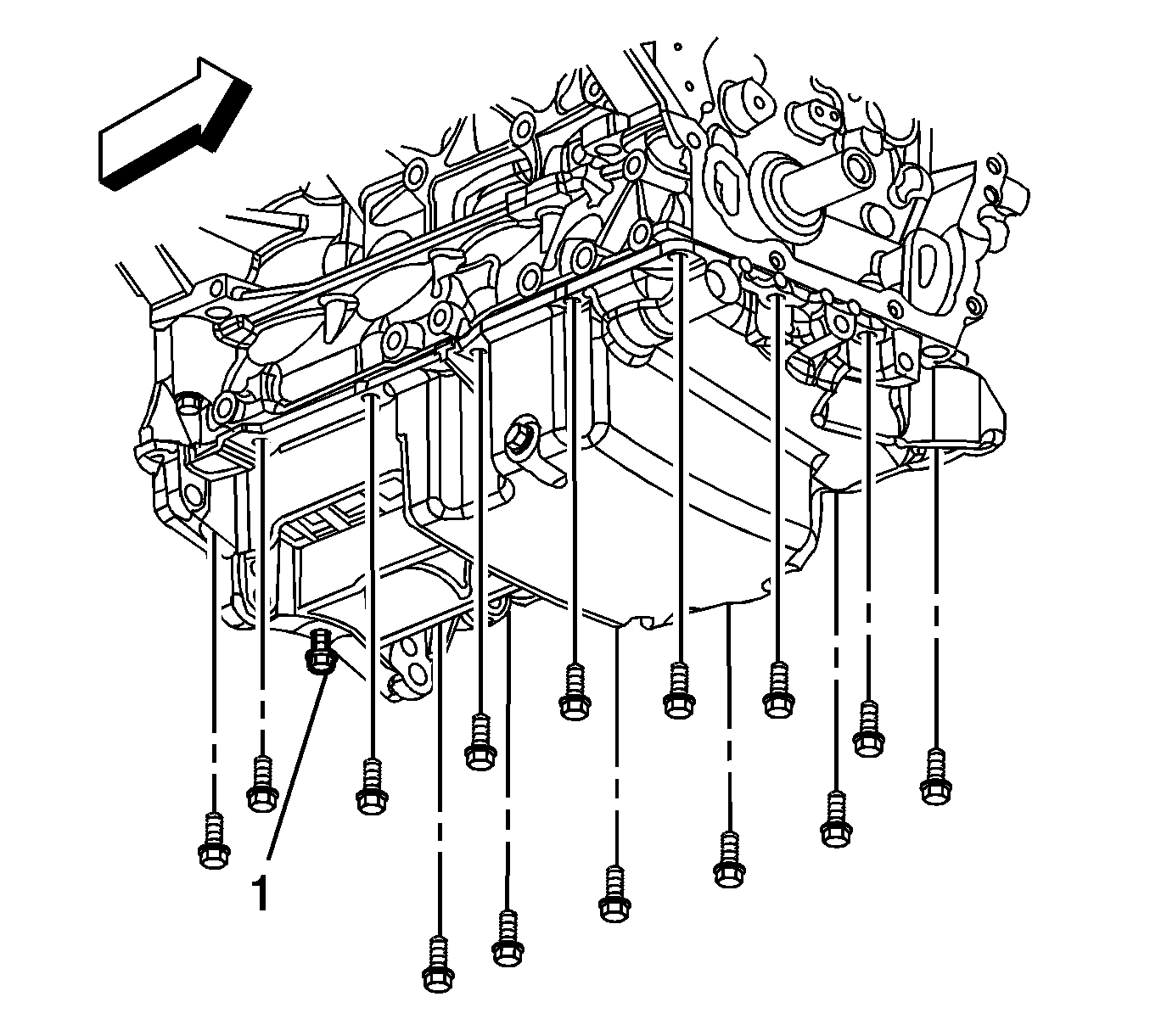
- Remove the 4 oil pan to transaxle bolts.
- Remove the oil pan bolts.
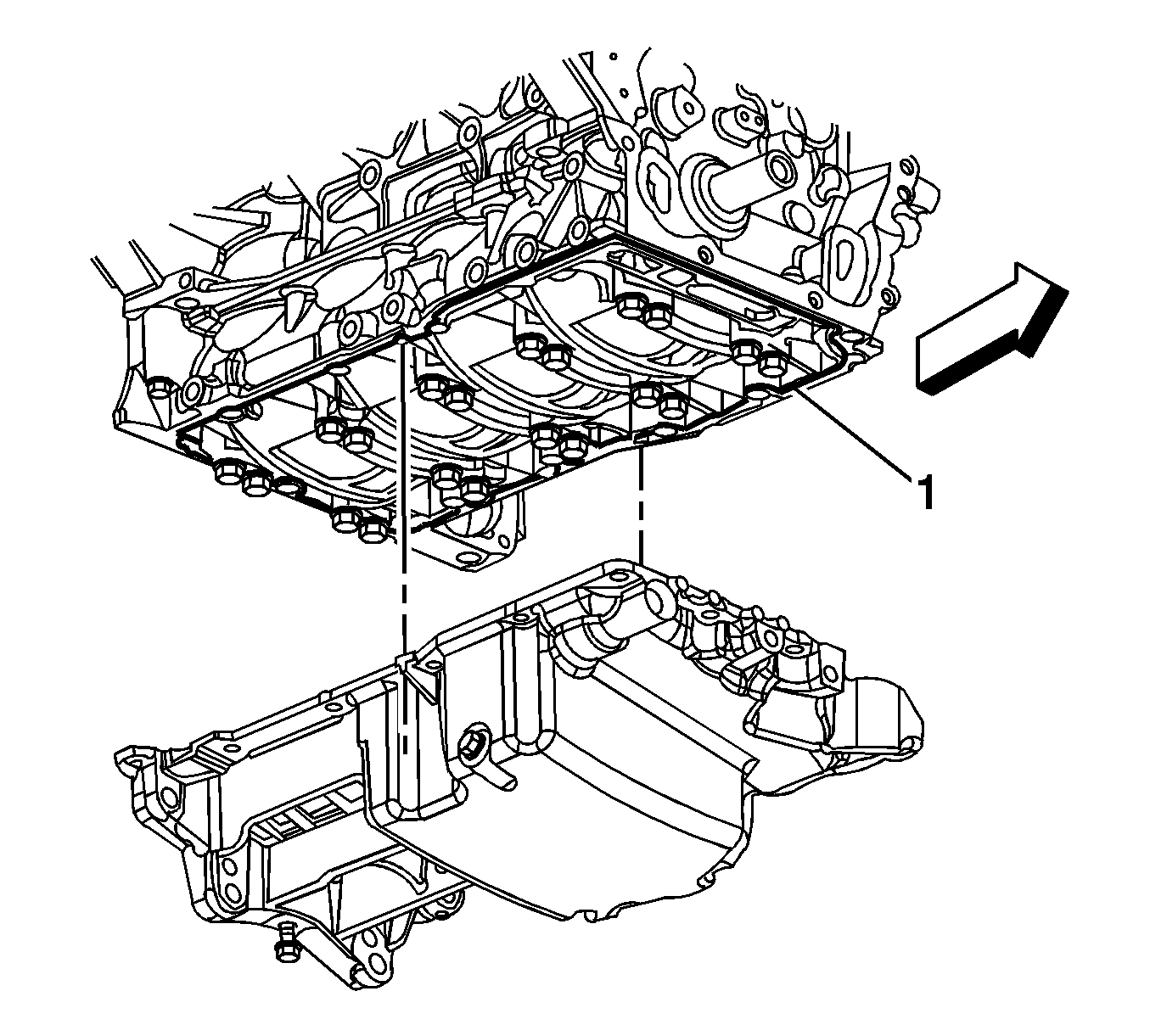
- Remove the oil pan
- Remove any old oil pan sealant (1).
Important: The support fixture bar must be installed to provide enough access to remove and properly tighten the oil pan bolts.
Installation Procedure
- Ensure that the oil pan and the sealing surface on the lower crankcase are free of all oil and debris.
- Apply a 2 mm bead of sealant (1) around the perimeter of the oil pan and the oil suction port opening. DO NOT over apply the sealant. More than a 2 mm bead is not required. Refer to Adhesives, Fluids, Lubricants, and Sealers.
- Install the oil pan.
- Install the oil pan bolts.
- Install the 4 oil pan to transaxle bolts.
- Tighten the oil pan bolts in the sequence shown.
- Install the generator control module coolant pump to the oil pan. Ensure that the anti-rotation tab is inserted into the hole in the oil pan.
- Install the generator control module coolant pump bolt.
- Connect the engine wiring harness electrical connector (1) to the generator control module coolant pump.
- Lower the vehicle.
- Using the engine support fixture, lower the engine.
- Place the engine mount onto the side rail studs.
- Install the engine mount to side rail nuts (1).
- Install engine mount to bracket bolts (2).
- Tighten the engine mount to bracket bolts in the following sequence.
- Remove the engine support fixture.
- Install the oil level indicator tube. Refer to Oil Level Indicator and Tube Replacement.
- Install the drive belt. Refer to Drive Belt Replacement.
- Fill the engine oil to the proper leve.


Notice: Refer to Fastener Notice in the Preface section.
Tighten
Tighten the bolts to 75 N·m (55 lb ft).
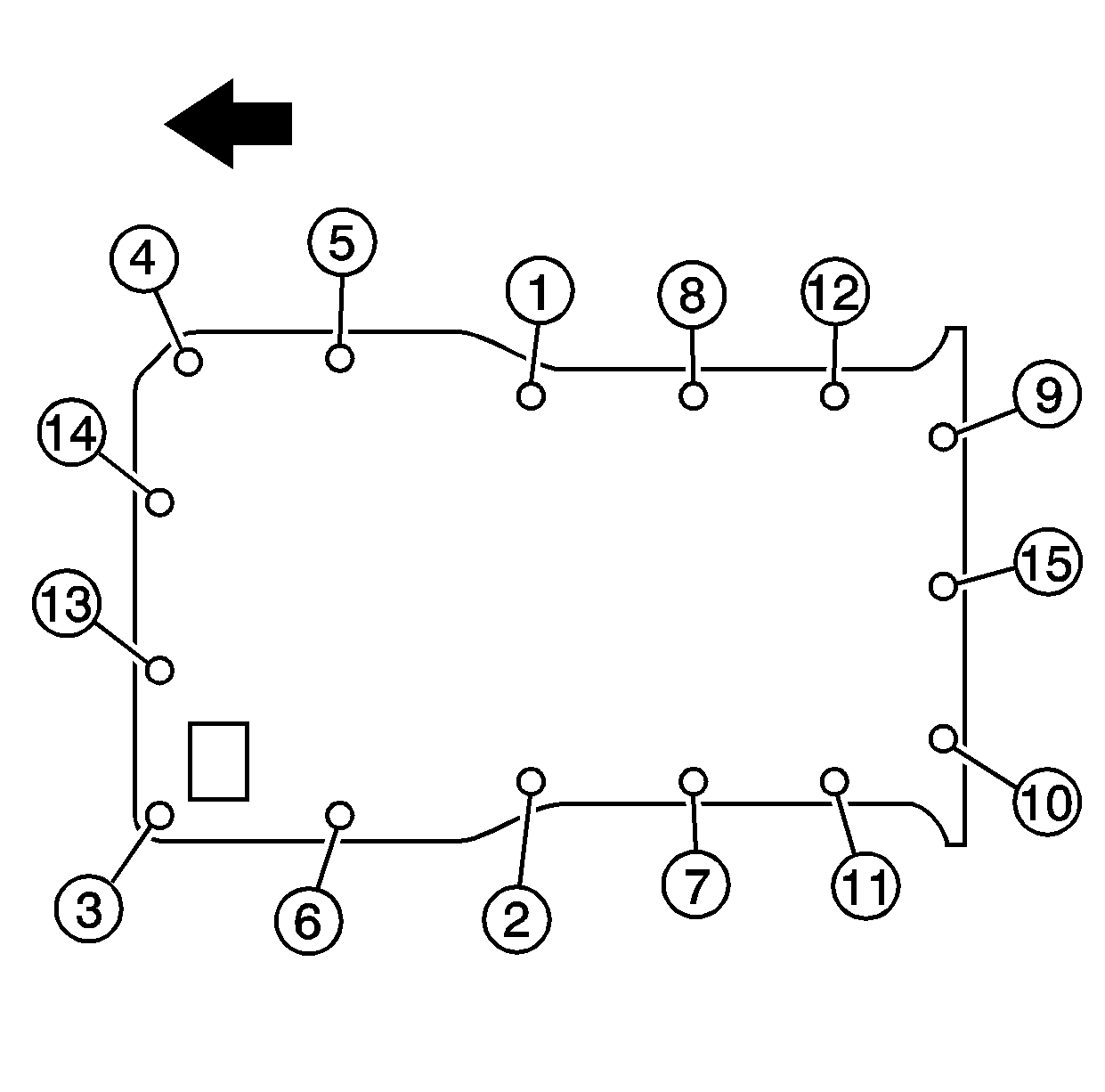
Tighten
Tighten the bolts to 25 N·m (18 lb ft).

Tighten
Tighten the bolt to 25 N·m (18 lb ft).


Tighten
Tighten the nuts to 100 N·m (74 lb ft).
| 15.1. | Middle |
| 15.2. | Rear |
| 15.3. | Front |
Tighten
Tighten the bolts to 50 N·m (37 lb ft).
