Tools Required
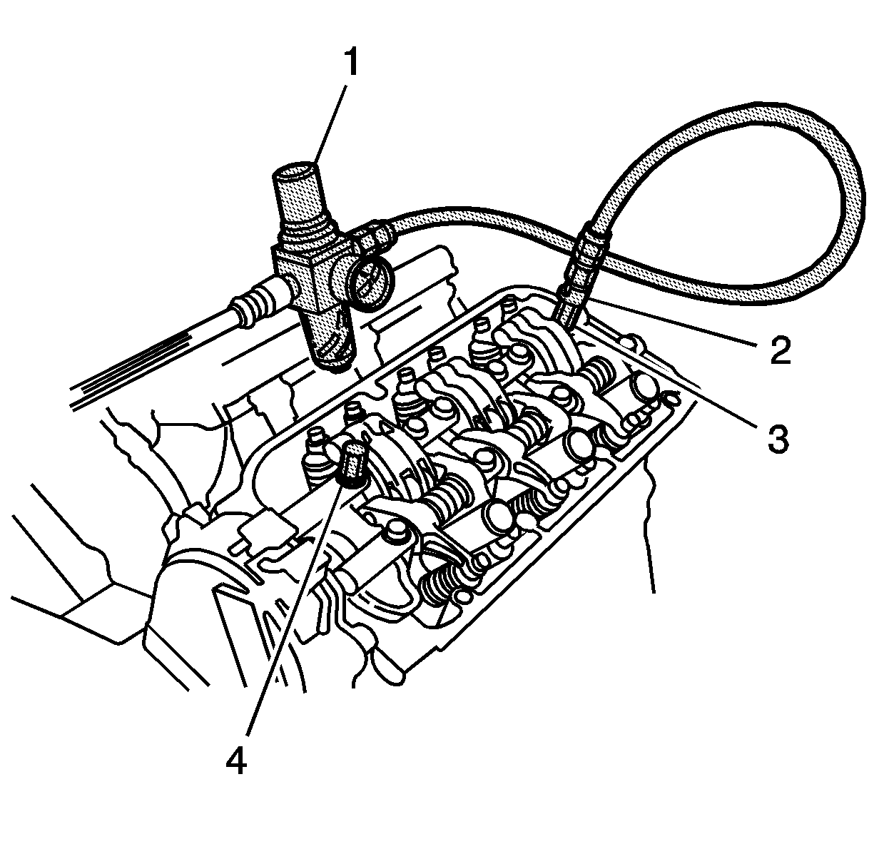
| • | EN 46339 Intake Rocker Arm Testing Adapter |
| • | EN 46340 Intake
Rocker Arm Testing Air Stopper |
| • | EN 46348 Intake
Rocker Arm Testing Air Pressure Regulator and Hose |
| • | EN 46352 Intake
Rocker Arm Testing Air Adapter |
- Start the engine and let it run for 5 minutes.
- Turn the ignition to the OFF position.
- Remove the intake air duct.
- Remove the brake booster vacuum hose from the intake manifold.
- Remove the ignition coils. Refer to
Valve Rocker Arm Cover Removal - Left Side
and
Valve Rocker Arm Cover Removal - Right Side
.
- Remove the intake manifold. Refer to
Intake Manifold Removal
.
- Remove the valve rocker arm covers. Refer to
Valve Rocker Arm Cover Removal - Left Side
and
Valve Rocker Arm Cover Removal - Right Side
.

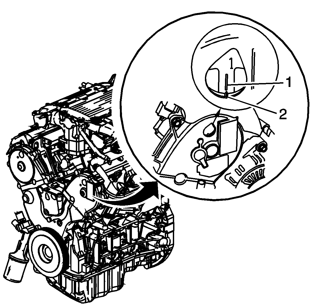
- Rotate the engine and
set number 1 piston at top dead center (TDC). In this position, the
mark on the camshaft sprocket (1) will align with the pointer on the
cover (2).

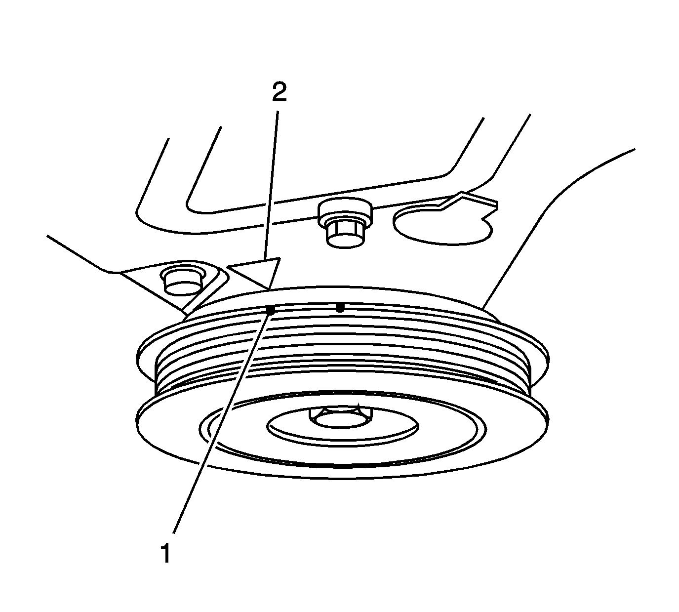
- With the engine rotated
and positioned with number 1 piston at TDC, the alignment mark on
the crankshaft balancer (1) will also be aligned with the pointer (2)
on the front cover.

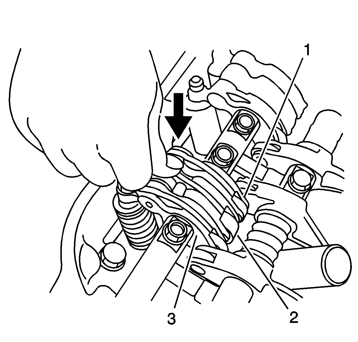
- Push on the intake mid
rocker arm (2) for the number 1 cylinder. The mid rocker arm
should move independently of the primary (1) and secondary (3)
rocker arms.
| • | If any of the rocker arm requires replacement, replace the primary,
mid, and secondary rocker arms as an assembly and test again. |
- Repeat Steps 9 and 10 on each of the remaining
intake mid rocker arms with the piston of the cylinder to be tested at TDC.
Important: In order to properly test the rocker arms, the shop air supply must
be higher than 690 kPa (100 psi).
- Inspect the valves for proper valve adjustment. Refer to
Valve Lash Adjustment
.
- Cover the timing belt with a shop towel to protect the belt.

- Remove the 2 end
intake rocker arm shaft mounting bolts and install the EN 46339
(3), EN 46340
(4), EN 46348
(1) and the EN 46352
(2).
- Connect the shop air supply.
- Loosen the valve on the regulator and adjust the air pressure
to 440-540 kPa (64-78 psi).

Important: If the synchronizing pistons do not move after applying shop air pressure,
move the primary and secondary rocker arms up and down manually.
- Ensure the primary rocker arm (2) and intake secondary rocker
arm (1) are mechanically connected by the piston and that the mid
rocker arm does not move independently when pushed manually. If any intake
mid rocker arms move independently of the primary and secondary rocker arms,
replace the rocker arms as an assembly.
- Inspect the valve lash adjusters. Replace lash adjusters that
do not move smoothly. Refer to
Valve Lash Adjuster Cleaning and Inspection
.
- Upon completion, inspect and ensure the Service Engine Soon
lamp is not illuminated.


