Tools Required
Valve Inspection
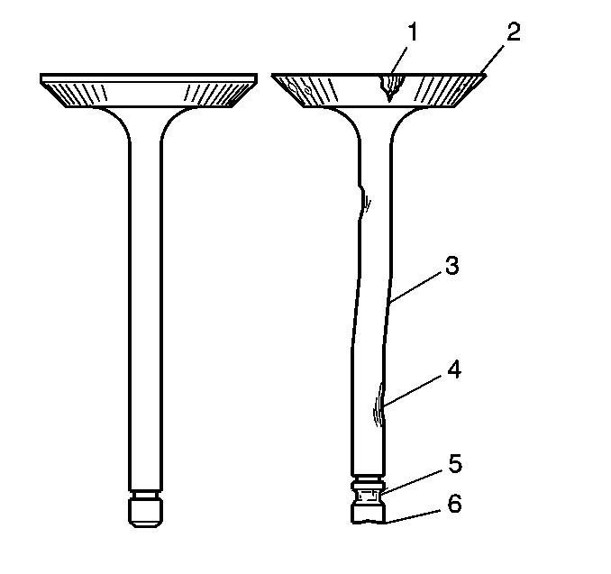
- Inspect the valve stems for scoring, wear or warpage.
| • | A valve stem that has excessive scoring (3 or 4) or wear (4 or 6) must be replaced. |
| • | A valve guide that is worn and has excessive stem-to-guide clearance must be replaced. |
- Inspect the valve for the following conditions:
| • | Burnt or eroded areas (1) |
| • | A worn or scored stem (4) |
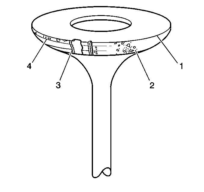
- Inspect the valve face for the following conditions:
| • | Worn or no margin (1 or 4) |
| • | Burnt or eroded areas (3) |
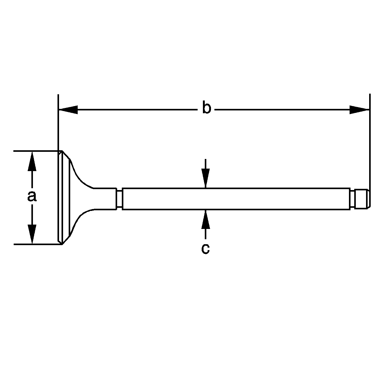
- Measure the valve.
Specification
| • | Intake valve head diameter (a): 34.9-35.1 mm (1.374-1.382 in) |
| • | Intake valve overall length (b): 115.7-116.3 mm (4.555-4.579 in) |
| • | Intake valve stem diameter (c) - new: 5.485-5.495 mm (0.2159-0.2163 in) |
| • | Intake valve stem diameter (c) - service limit: 5.455 mm (0.2148 in) |
| • | Exhaust valve head diameter (a): 29.9-30.1 mm (1.177-1.185 in) |
| • | Exhaust valve overall length (b): 113.9-114.5 mm (4.484-4.508 in) |
| • | Exhaust valve stem diameter (c) - new: 5.45-5.46 mm (0.2146-0.215 in) |
| • | Exhaust valve stem diameter (c) - service limit: 5.42 mm (0.2134 in) |
Measuring Valve Stem-to-Guide Clearance - Dial Indicator Method
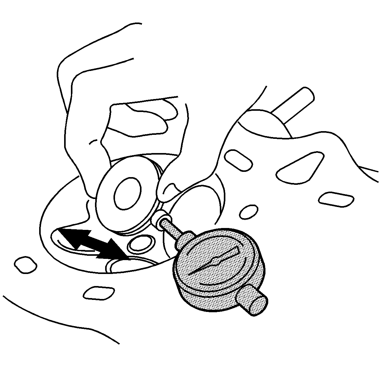
- Slide the valve out of the guide, approximately 10 mm (0.4 in),
in order to measure the guide-to-stem clearance with the
SA9179NE
. Rock the stem in the direction of the normal thrust.
| • | If the measurement exceeds the service limit, install a new valve and measure again. |
| • | If the measurement is within the service limit, assemble using existing valve. |
| • | If the measurement with a new valve exceeds the service limit, replace the valve guide. |
- Compare the measurements to the specifications.
Specification
| • | Intake valve stem-to-guide clearance - new: 0.02-0.045 mm (0.0008-0.0018 in) |
| • | Intake valve stem-to-guide clearance - service limit: 0.08 mm (0.003 in) |
| • | Exhaust valve stem-to-guide clearance - new: 0.055-0.08 mm (0.0022-0.0031 in) |
| • | Exhaust valve stem-to-guide clearance - service limit: 0.11 mm (0.004 in) |
Measuring Valve Stem-to-Guide Clearance - Micrometer Method

- Measure the outside diameter (O.D.) of the valve stem (c). Take measurements in 3 places along the stem.
- Measure the inside diameter (I.D.) of the valve guide (a). Take measurements in 3 places along the guide bore.
- Calculate the stem-to-guide clearance (b).
Specification
| • | Intake valve stem-to-guide clearance - new: 0.02-0.045 mm (0.0008-0.0018 in) |
| • | Intake valve stem-to-guide clearance - service limit: 0.08 mm (0.003 in) |
| • | Exhaust valve stem-to-guide clearance - new: 0.055-0.08 mm (0.0022-0.0031 in) |
| • | Exhaust valve stem-to-guide clearance - service limit: 0.11 mm (0.004 in) |
Valve Guide Replacement
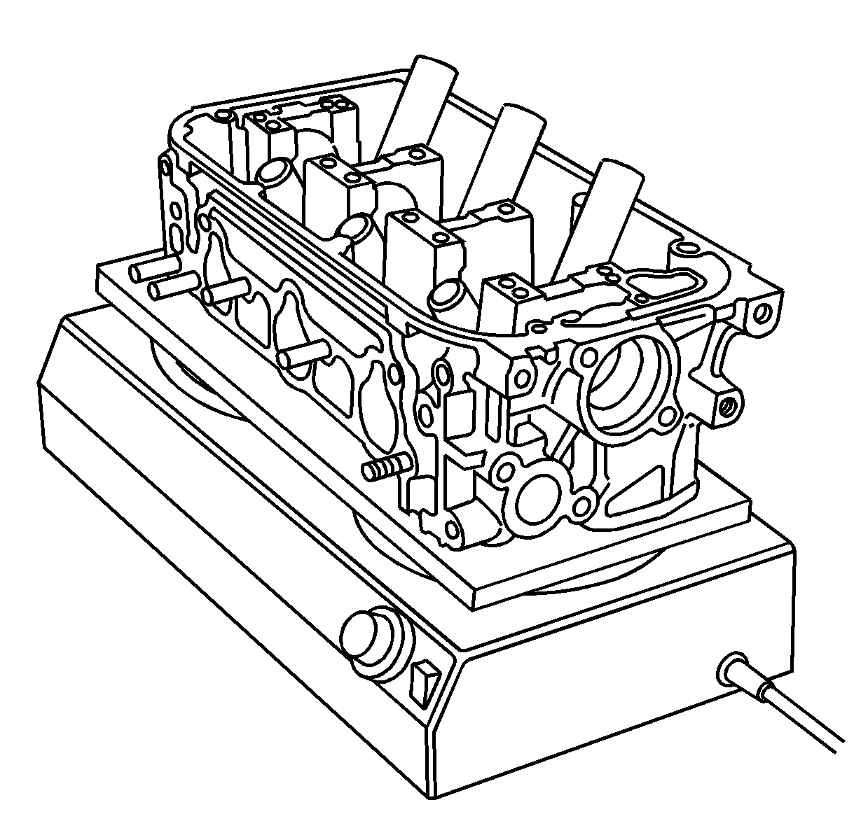
Important: Do not heat the cylinder head in excess of 150°C (300°F). Excessive heating of the cylinder head may loosen the valve seats.
- Select the proper replacement guides and chill them in a freezer for approximately 1 hour.
- Use a hot plate or an oven to evenly heat the cylinder head to 150°C (300°F). Monitor the temperature with a thermometer.
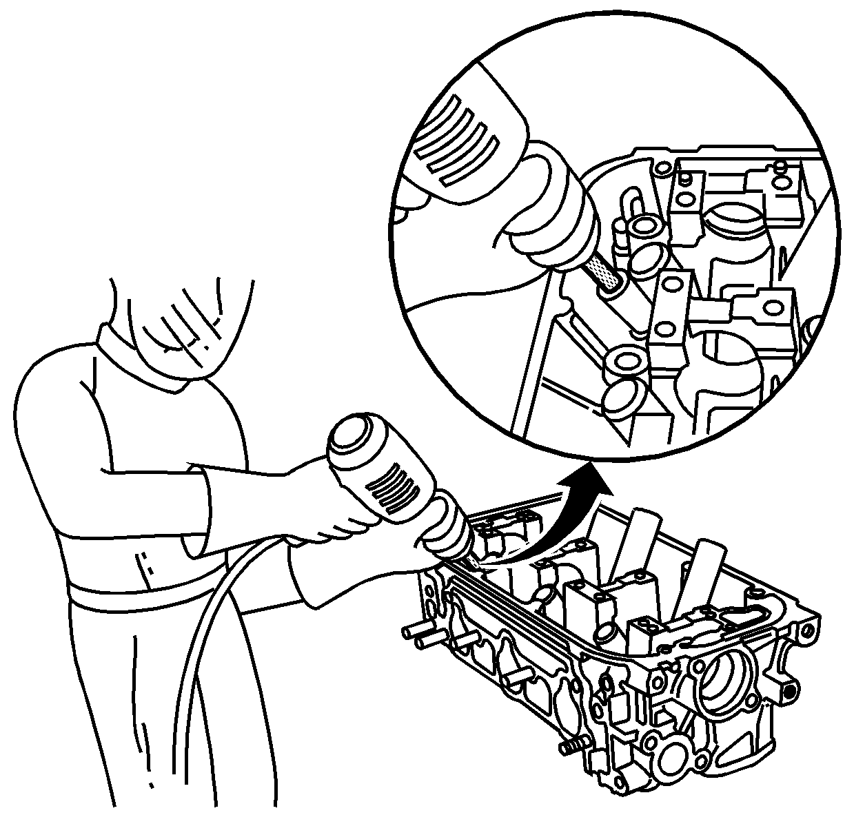
- Working from the camshaft, or top, side, use the
EN 46341
and an air hammer in order to drive the guide approximately 2 mm (0.1 in) towards the combustion chamber. This action will remove some of the carbon from the guide and ease in guide removal.
Important: Drill the guides only in extreme cases. Use extreme care not to break the guide and damage the cylinder head.
- Turn the head over and use the
EN 46341
and an air hammer to drive the guide out of the cylinder head. If the valve guide will not move, enlarge the guide bore with an 8 mm (5/16 in)
drill bit.
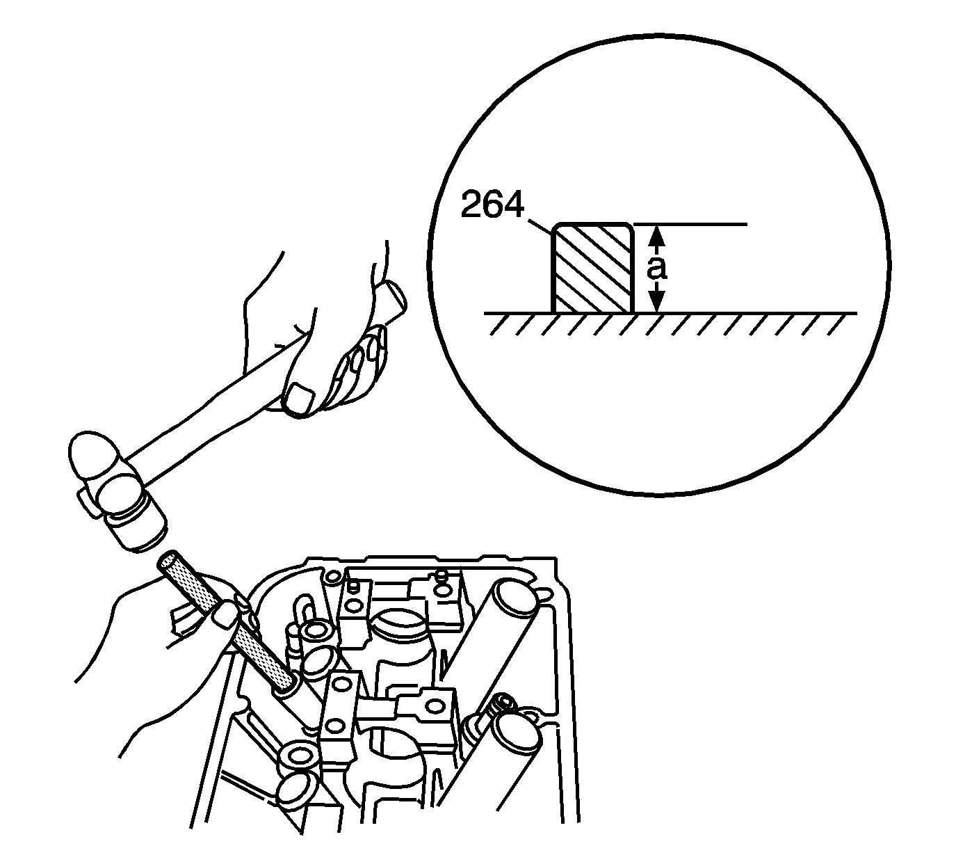
- Use the
EN 46341
in order
to install the NEW guides into the cylinder head. Remove the valve guides, 1 at a time from the freezer, just prior to installation.
- Measure the guide (264) for the properly installed height (a).
Specification
| • | Intake valve guide installed height: 21.20-22.2 mm (0.835-0.874 in) |
| • | Exhaust valve guide installed height: 20.63-21.63 mm (0.812-0.852 in) |
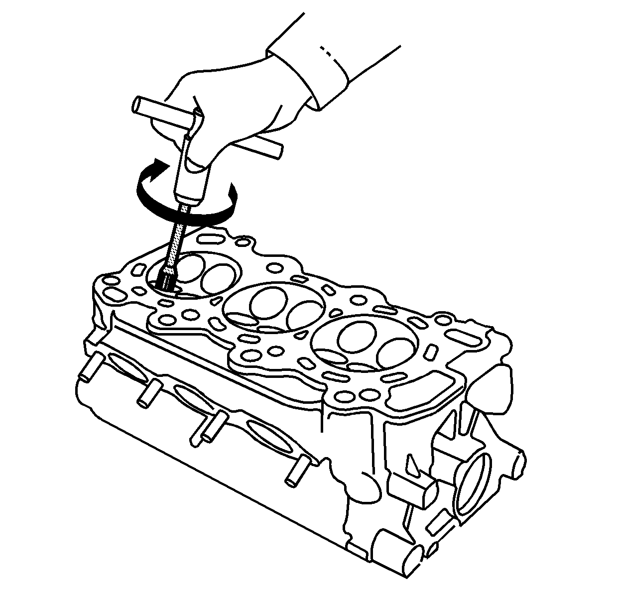
- Coat the
EN 46345
and the
valve guide with cutting oil.
- Use the
EN 46345
to ream the guide to the proper size. Rotate the reamer clockwise the full length of the guide bore. Continue to rotate the reamer clockwise while removing from the guide bore.
- Clean the guide in detergent and water to remove cutting residue.
- Measure the valve stem-to-guide clearance. The valve should slide freely in the guide without exerting pressure.
Valve Seat Reconditioning
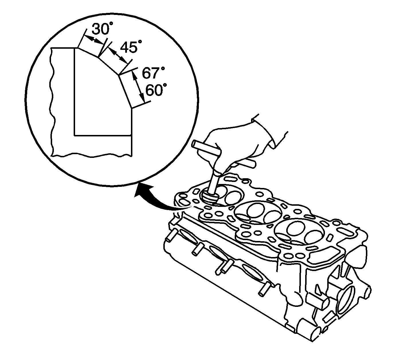
Important: If the valve guides are worn, they must be replaced prior to cutting the valve seats.
- Renew the valve seats using a seat cutting tool.
| 1.1. | Carefully cut a 45 degree seat, removing only enough material to ensure a smooth and concentric seat. |
| 1.2. | Bevel the upper edge of the seat with a 30 degree cutter. |
| 1.3. | Bevel the lower edge of the intake valve seat with a 67 degree cutter. |
| 1.4. | Bevel the lower edge of the exhaust valve seat with a 60 degree cutter. |
| 1.5. | Make 1 additional light pass with a 45 degree cutter in order to remove any possible burrs created during the cutting process. |
Specification
| • | Valve seat width - new: 1.25-1.55 mm (0.049-0.061 in) |
| • | Valve seat width - service limit: 2.0 mm (0.079 in) |
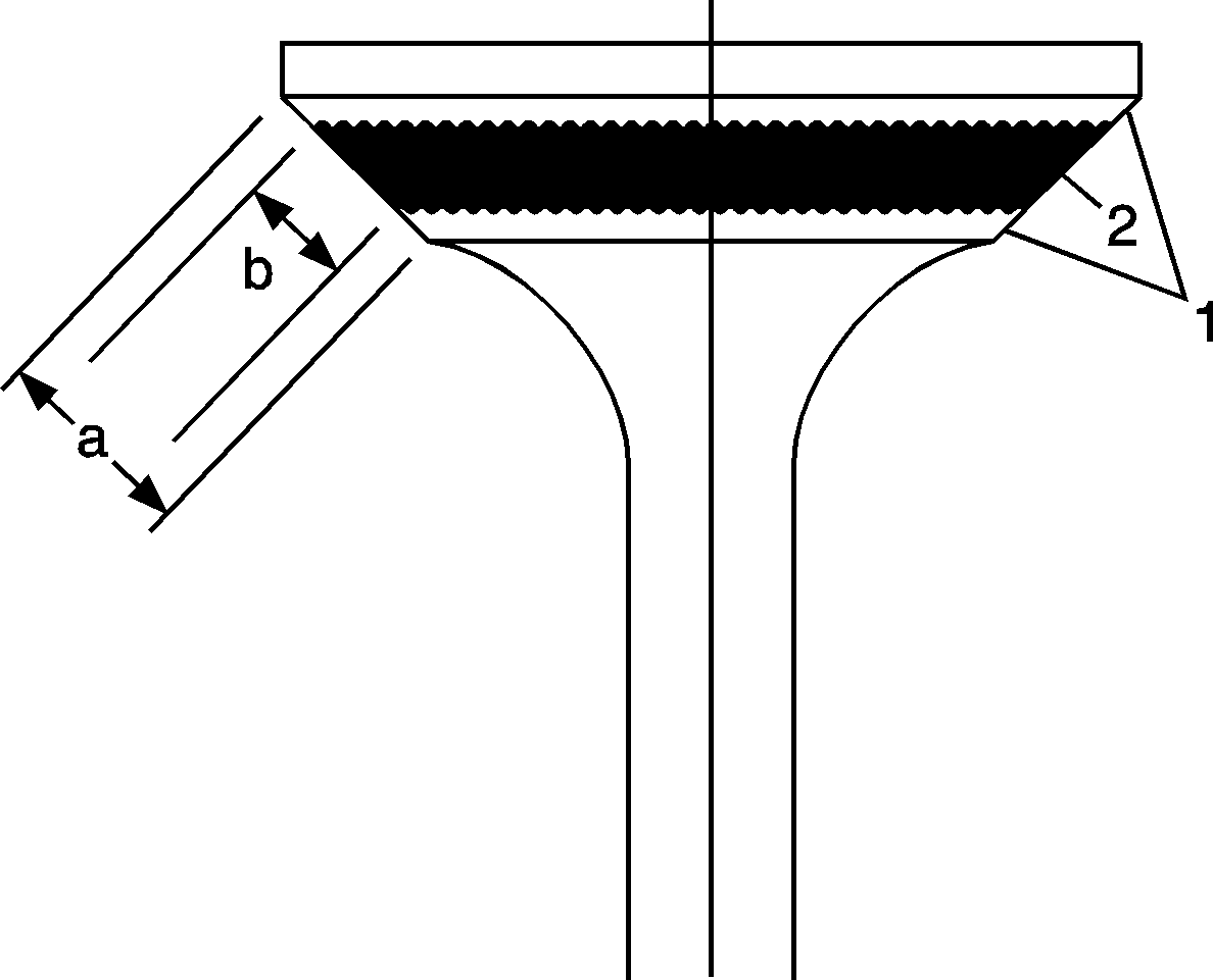
- After resurfacing the valve and/or seat, inspect for even valve seating. Apply
Gear Pattern Checking Grease GM P/N 1052351 (Canadian P/N 10953497), or equivalent, to the valve face (1). Insert the valve in its original location in the cylinder head. Lift and snap the valve closed against the seat several
times.
- The actual valve seating surface (2) should be centered on the seat.
| • | If the seat surface is too high or closer to the valve stem, a second cut with the 67 degree intake or 60 degree exhaust cutter must be made. An additional pass with the 45 degree cutter must also be made prior to completion. |
| • | If the seat surface is too low or closer to the large end of the valve, a second cut with the 30 degree cutter must be made. An additional pass with the 45 degree cutter must also be made prior to completion. |
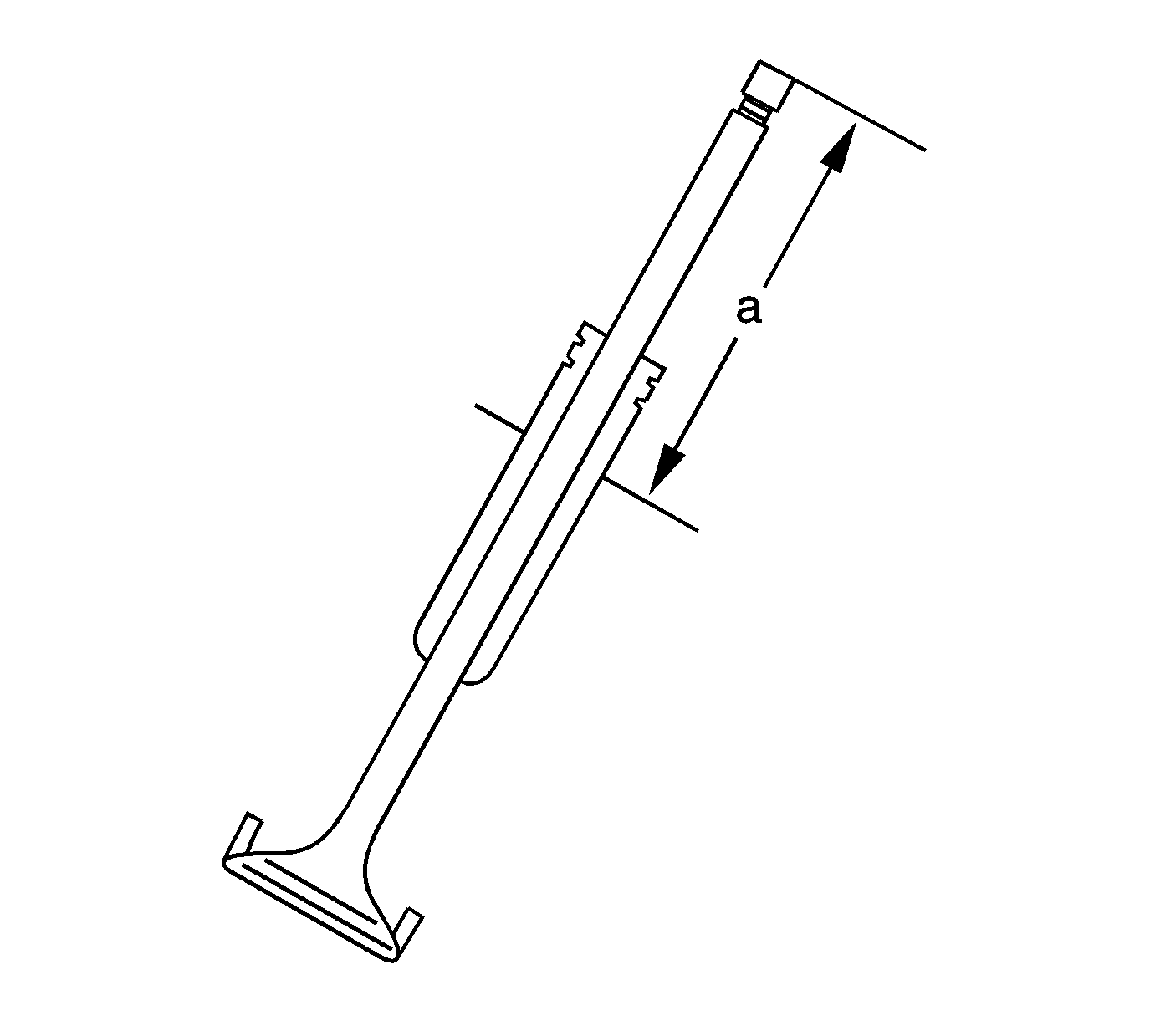
- Insert the intake and exhaust valves into the cylinder head.
| 4.1. | Measure the valve stem installed height (a). |
| 4.2. | If the valve stem installed height is over the service limit, replace the valve and measure again. |
| 4.3. | If the installed height remains over the service limit, replace the cylinder head. |
Specification
| • | Intake valve stem installed height - new: 46.75-47.55 mm (1.841-1.872 in) |
| • | Intake valve stem installed height - service limit: 47.8 mm (1.882 in) |
| • | Exhaust valve stem installed height - new: 46.68-47.48 mm (1.838-1.869 in) |
| • | Exhaust valve stem installed height - service limit: 47.73 mm (1.879 in) |


