For 1990-2009 cars only
- Install the bolts (216) and nuts (217). Do not tighten the nuts at this time.
- Install the intake valve rocker arm assemblies (215) onto the shaft (221).
- Install the bolts (214) to the shaft (221).
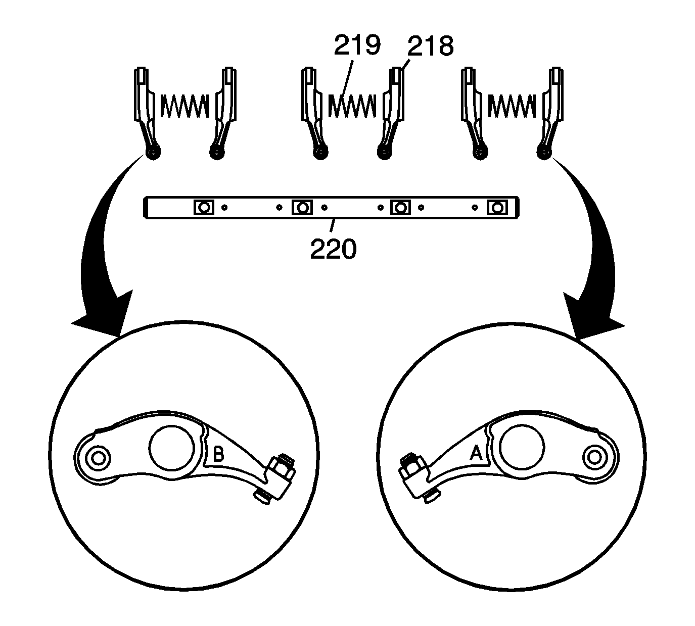
- Install the exhaust valve rocker arms (218) and springs (219) onto the shaft (220).
- Note the installed position of the exhaust valve rocker arms (218).
- Install the bolts to the shaft (220).
- Install the lash adjusters (207).
- Install the intake and exhaust rocker arm and shaft assemblies and bolts (214).
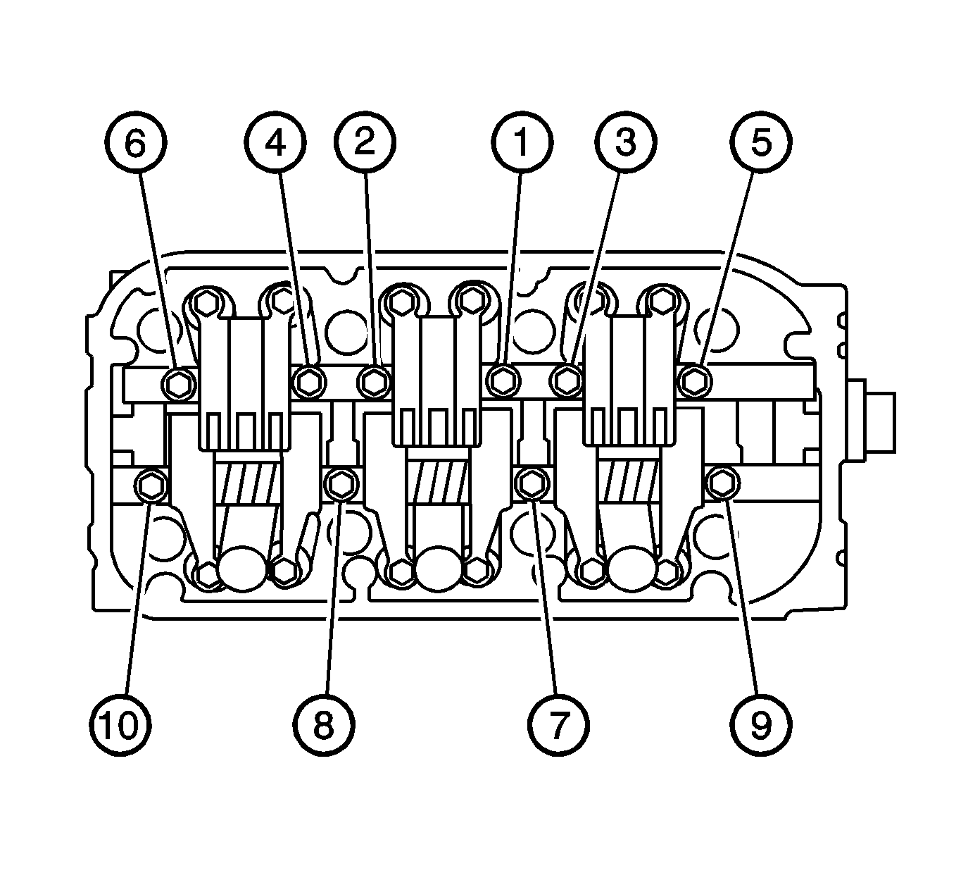
- Tighten the left side rocker shaft retaining bolts in sequence. Tighten the bolts 2 turns at a time, in sequence, to ensure that the rocker arms do not bind on the valves.
- Tighten the bolts in sequence a first pass to 12 N·m (106 lb in).
- Tighten the bolts in sequence a final pass to 24 N·m (17 lb ft).
- Tighten the right side rocker shaft retaining bolts in sequence. Tighten the bolts 2 turns at a time in sequence, to ensure that the rocker arms do not bind on the valves.
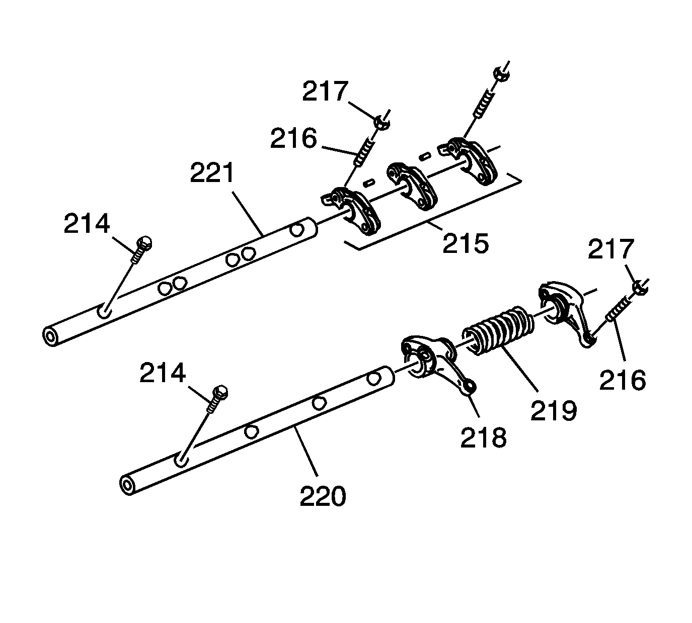
Important: Identify parts as they are removed so they can be installed in their original locations if used again. When removing or installing the rocker arm shaft assembly, do not remove the rocker arm shaft mounting bolts. The bolts will retain the springs and rocker arms onto the shafts.
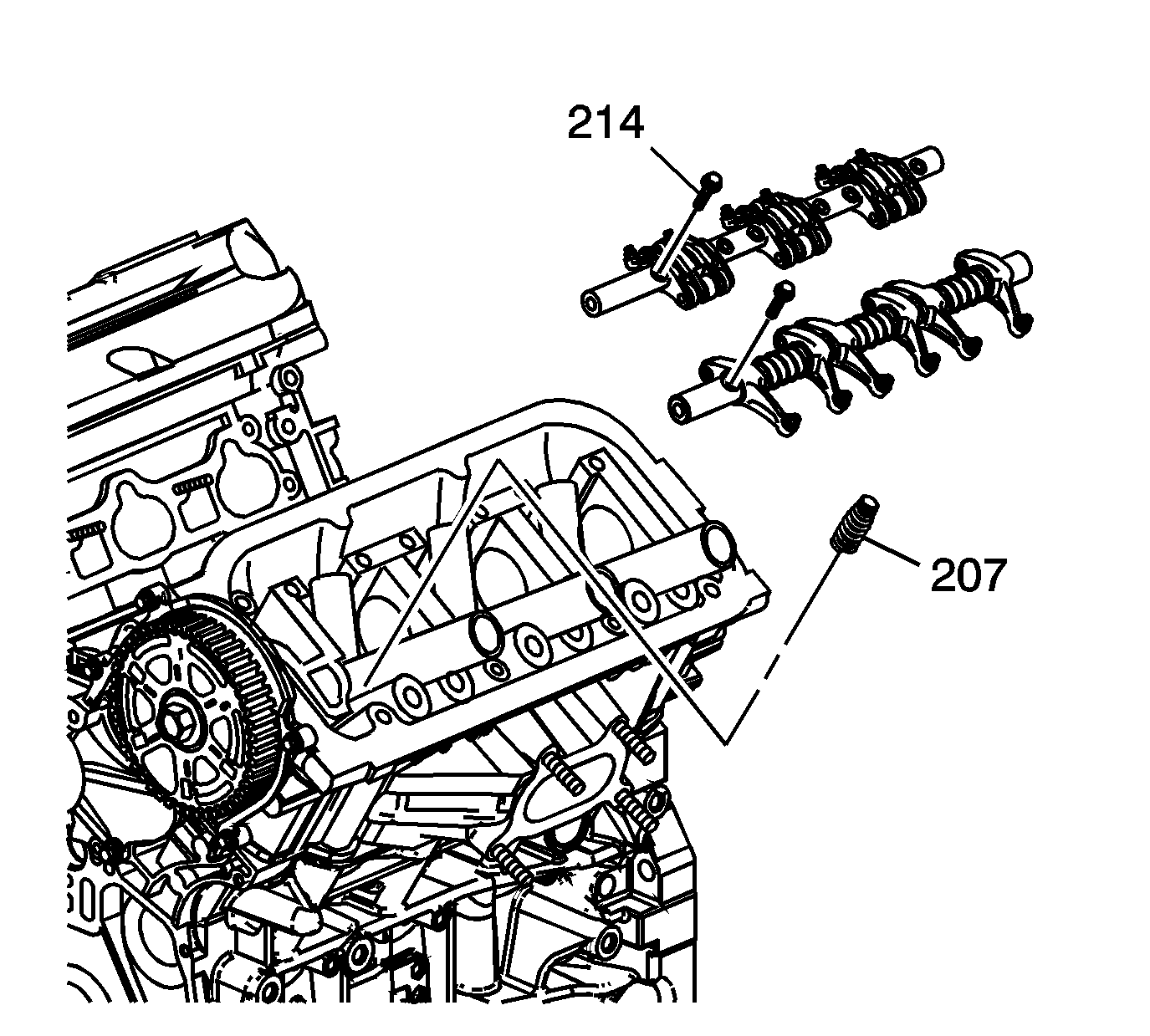
Important: The intake rocker arm shaft front locating pin serves as an oil passage for intake rocker arm control system operation. During assembly, use care to locate the shaft onto the pin. Replace pins that are bent or damaged.
Notice: Refer to Fastener Notice in the Preface section.
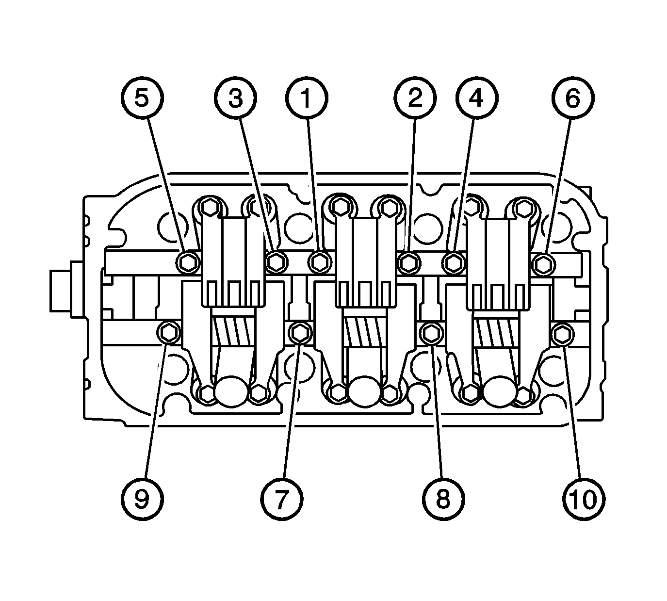
Tighten
