For 1990-2009 cars only
Removal Procedure
- Remove the console shift lever bezel. Refer to Console Shift Lever Bezel Replacement .
- Remove the instrument panel (I/P) storage compartment. Refer to Instrument Panel Storage Compartment Replacement .
- Remove the center trim bezel. Refer to Instrument Panel Accessory Bezel Replacement .
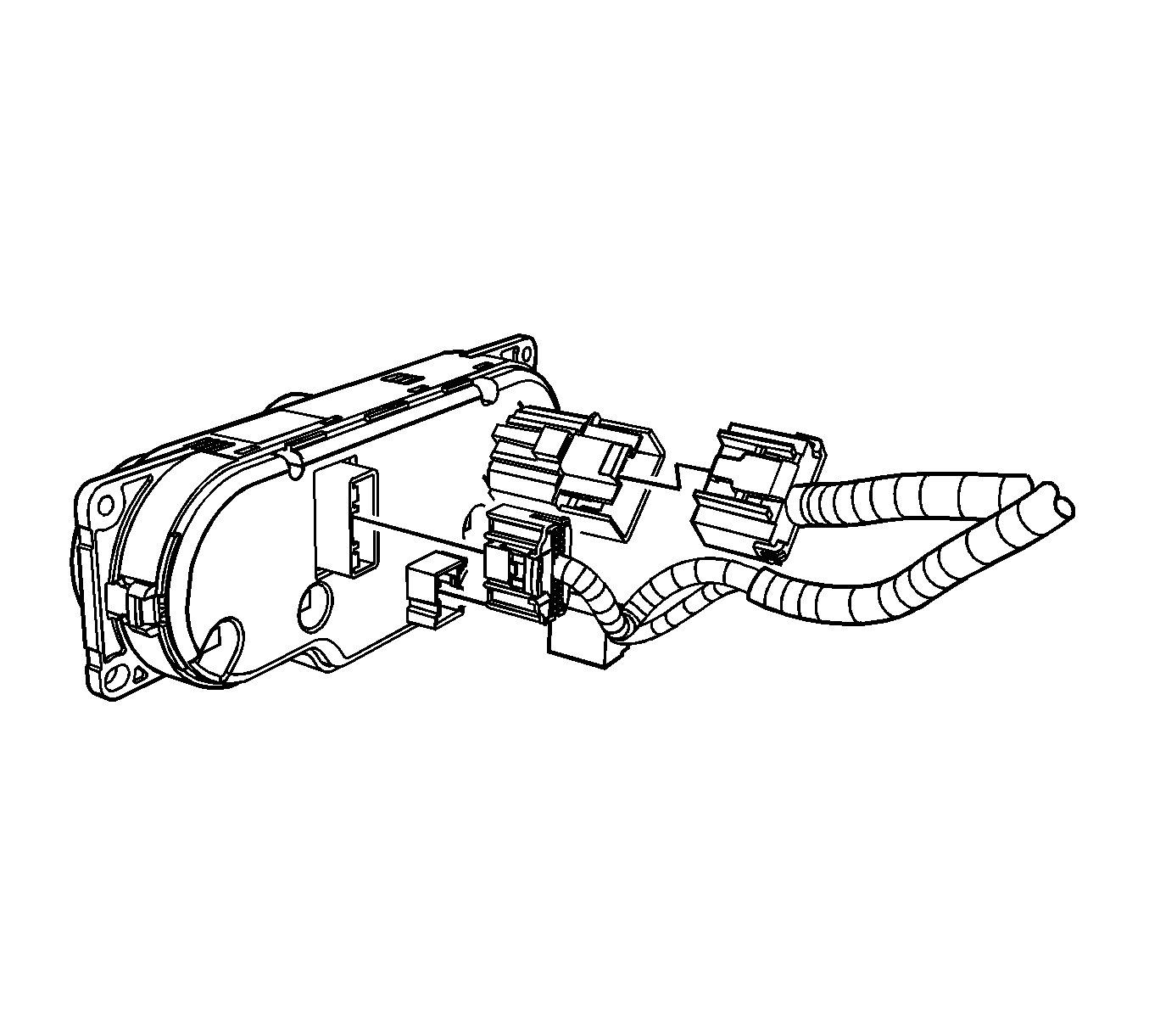
- Disconnect the electrical connectors from the HVAC control module.
- Disconnect the remaining electrical connectors from the center trim bezel.
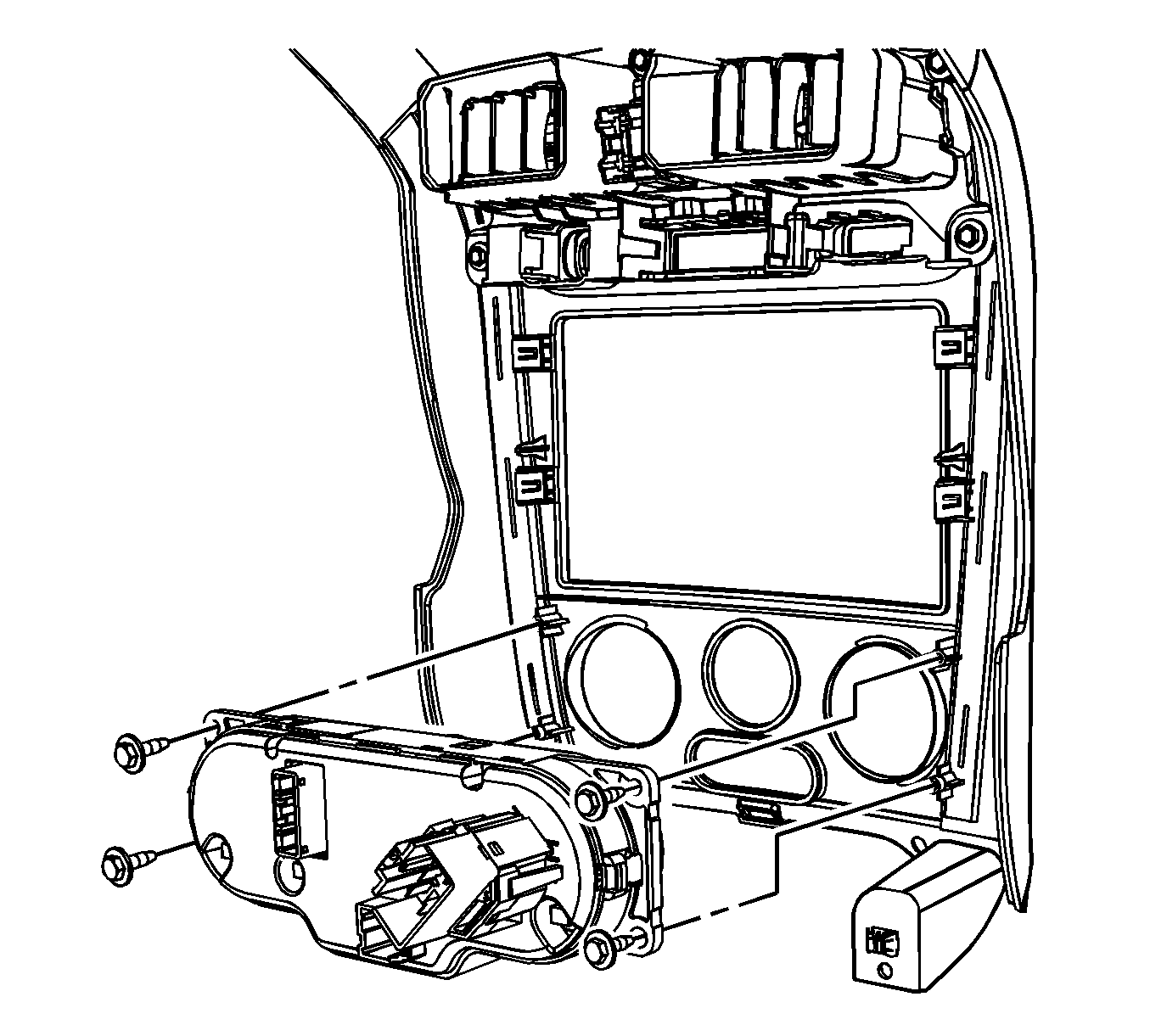
- Remove the HVAC control module screws from the center trim bezel.
- Remove the HVAC control module from the center trim bezel.


Installation Procedure
- Install the HVAC control module to the center trim bezel.
- Install the HVAC control module screws to the center trim bezel.
- Connect the electrical connectors to the HVAC control module.
- Connect the remaining electrical connectors to the center trim bezel.
- Install the center trim bezel to the I/P. Refer to Instrument Panel Accessory Bezel Replacement .
- Install the I/P storage compartment. Refer to Instrument Panel Storage Compartment Replacement .
- Install the console shift lever bezel. Refer to Console Shift Lever Bezel Replacement .
- Calibrate the mode door by simultaneously pushing the A/C and RECIRC buttons on the HVAC control module 3 times each, within 2 seconds of initial push.
- Cycle the ignition and verify proper operation.
- Refer to Control Module References for programming and setup information.

Notice: Refer to Fastener Notice in the Preface section.
Tighten
Tighten the screws to 2.5 N·m (22 lb in).

Important: Any time an HVAC module mode actuator or the HVAC control module is replaced, the HVAC control module must be calibrated to ensure proper air distribution.
| 8.1. | The A/C and RECIRC button LED's will flash while this calibration is taking place. |
| 8.2. | The calibration will take anywhere between 10-30 seconds depending on battery voltage. |
| 8.3. | The LED's will quit flashing when the calibration is complete. |
